
Related Manuals for HP 5300xl Series


Summary of Contents for HP 5300xl Series
- Page 1 5300xl switches www.hp.com/go/hpprocurve...
- Page 3 HP ProCurve Series 5300xl Switches Installation and Getting Started Guide...
- Page 4 Hewlett-Packard. performance, or use of this material. The only warranties for HP products and services are set Publication Number forth in the express warranty statements accompanying such products and services. Nothing herein should be 5990-8835 construed as constituting an additional warranty.
-
Page 5: Table Of Contents
Contents 1 Introducing the HP ProCurve Series 5300xl Switches Front of the Switch ..........1-4 LEDs . - Page 6 Downloading New Code ........4-13 HP Customer Support Services ....... . 4-13...
- Page 7 A Specifications Physical ........... A-1 Electrical .
- Page 8 Safety Information (Japan) ........C-6 Safety Information (China) ........C-7 EMC Regulatory Statements .
-
Page 9: Introducing The Hp Procurve Series 5300Xl Switches
Introducing the HP ProCurve Series 5300xl Switches The HP ProCurve Series 5300xl Switches include the Switch 5304xl and its bundles, the Switch 5348xl and the Switch 5332xl-Gigabit, and the Switch 5308xl and its bundles, the Switch 5372xl and the Switch 5348xl-Gigabit. They are multiport modular switches that provide Layer 3 routing features, and that feature low latency for high-speed networking. - Page 10 Introducing the HP ProCurve Series 5300xl Switches HP ProCurve Switch 5304xl-32G bundle (J8166A) with two 16 port 100/1000-T xl Modules preinstalled Switch 5308xl and Switch 5372xl and the Switch 5308xl-48G. The Switch 5308xl is available as an open 8-slot chassis (J4819A), as the Switch...
- Page 11 Switch 5308xl-48G bundle (J8167A) with three 100/1000-T xl Modules preinstalled See “Switch Features” on page 1-10 for a list of the switch modules that you can install in the HP ProCurve Series 5300xl Switches (modules available when this manual was printed).
-
Page 12: Front Of The Switch
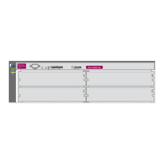
J4820A Self Test LED Switch Modules and slots with Link and Mode LEDs for each port located on each module This illustration shows the 5348xl, but the labeling and descriptions apply to all of the HP ProCurve Series 5300xl switches. -
Page 13: Leds
Introducing the HP ProCurve Series 5300xl Switches Front of the Switch LEDs As described in the next two tables, there are LEDs on the switch chassis and on the switch modules that keep you informed of the status of the switch and the network connections. - Page 14 • no active network cable is connected to the port • the port is not receiving link beat or sufficient light • the port has been disabled through the switch console, the web browser interface, HP ProCurve Manager, or other network management tool. † Flashing The port has failed self test.
-
Page 15: Led Mode Select Button And Indicator Leds
Introducing the HP ProCurve Series 5300xl Switches Front of the Switch LED Mode Select Button and Indicator LEDs To optimize the amount of information that can be displayed for each of the switch ports, the Series 5300xl Switches use a Mode LED for each port. The... -
Page 16: Console Port
The counters are displayed in the switch console interface, the switch web browser interface, and through SNMP network management applications, such as HP ProCurve Manager for Hubs & Switches. Press the Reset button also after changing the module type that is installed in any of the switch module slots while the switch is powered on. -
Page 17: Back Of The Switch
Hz. There are no voltage range settings required. Slot for Redundant Power Supply A second, load-sharing redundant power supply (HP ProCurve Switch gl/xl RPS, J4839A) can be installed in the back of the Series 5300xl Switches. To provide true redundancy, this second power supply should be connected to a different AC power source from the other supply. -
Page 18: Switch Features
802.3af compliant devices. For more information on PoE power refer to the HP ProCurve PoE Planning and Implementation Guide. For more information on the J8161A module refer to the HP ProCurve Switch xl Modules Installation Guide. C a u t i o n For safe and reliable operation, disconnect EPS cable before installing or removing J8161A modules. - Page 19 (CLI) and a slightly reduced feature set accessible through an intuitive menu interface. • HP ProCurve Manager for Hubs & Switches—an SNMP-based graph- ical interface that is used to manage your entire network, included with your new switch.
- Page 20 — This page is intentionally unused. —...
-
Page 21: Installing The Series 5300Xl Switches
Installing the Series 5300xl Switches The HP Series 5300xl Switches are easily installed. They come with an accessory kit that includes the brackets for mounting the switch in a standard 19-inch telco rack, in an equipment cabinet, or on a wall. The switches have rubber feet already attached so they can be securely located on a horizontal surface. -
Page 22: Installation Procedures
(page 2-7). The Series 5300xl Switches have four or eight universal slots for installing any of the HP ProCurve Switch xl modules. The Switch 5372xl has three 24-port 10/100-TX xl Modules preinstalled, and the Switch 5348xl has two 24-port 10/100-TX xl Modules preinstalled. - Page 23 N o t e The 10/100Base-TX ports on the 10/100-TX and PoE xl Modules have the HP Auto-MDIX feature, and the 100/1000Base-T ports on the 100/1000-T xl Module comply with IEEE 802.3x standard which includes the Auto MDI/MDI-X feature. These two features operate the same and allow you to use straight-through twisted-pair cable for all of your twisted-pair network connections.
- Page 24 C a u t i o n For safe and reliable operation, disconnect EPS cable before installing or removing J8161A modules. For more information refer to the HP ProCurve Switch xl Modules Installation Guide.
-
Page 25: Prepare The Installation Site
Note: HP does not support PoE for 1000 Mbps operation. The Auto MDI/MDI-X feature only works when the port is in auto-negotiation mode. -
Page 26: Installation Location
Installing the Series 5300xl Switches Installation Procedures Port Type Cable Type Length Limits Fiber Optic Cables Gigabit-SX Multimode fiber-optic cables fitted with LC 220 meters to 550 meters depending on the (on Gigabit-SX-LC connectors cable used. See “Fiber-Optic Cables” on mini-GBIC) page B-3 for more information. -
Page 27: Install Switch Xl Modules
C a u t i o n Make sure you install only HP ProCurve Switch xl Modules. Switch gl Modules will fit into your Switch xl slots, but they will not operate. Avoid any electrostatic discharge problems by handling the modules only by their bulkheads. - Page 28 Installing the Series 5300xl Switches Installation Procedures Insert module into the guides and slide it in until it is fully inserted. “Low-force” connector. High insertion force is not needed and should not be used. For best results, push near both screws. The module is fully inserted when the module bulkhead is contacting, or very close to contacting...
-
Page 29: Optional) Install Second Power Supply
3. (Optional) Install Second Power Supply A second, load-sharing redundant power supply (HP ProCurve Switch gl/xl RPS, HP J4839A) can be installed in the back of the switch. To provide true redundancy, this second power supply should be connected to a different AC power source from the other supply. - Page 30 Installing the Series 5300xl Switches Installation Procedures Insert the power supply into the opening, then slide it all the way in until it connects to the switch. The power supply face plate will be flush with the back face of the switch.
-
Page 31: Verify The Switch Passes Self Test
Installing the Series 5300xl Switches Installation Procedures 4. Verify the Switch Passes Self Test After you have installed any modules and the optional second power supply, but before mounting the switch in its network location, you should first verify it is working properly by plugging it into a power source and verifying it passes its self test. -
Page 32: Led Behavior
Installing the Series 5300xl Switches Installation Procedures Switch Chassis LEDs hp procurve switch 5304xl Status J4850A Reset Clear Self Power Modules LED Mode Select Console Test switch module LEDs: Link and Mode LEDs for each port procurve xl module J4820A When the switch is powered on, it performs its diagnostic self test. -
Page 33: Mount The Switch
Installing the Series 5300xl Switches Installation Procedures 5. Mount the Switch After the modules and optional power supply are installed and you have verified the switch passes self test, you are ready to mount the switch in a stable location. The Series 5300xl Switches can be mounted in these ways: in a rack or cabinet on a horizontal surface on a wall... - Page 34 Installing the Series 5300xl Switches Installation Procedures Attaching brackets to the Switch 5304xl. 10 mm M4 screws Attaching brackets to the Switch 5308xl. 10 mm M4 screws 2-14...
- Page 35 Installing the Series 5300xl Switches Installation Procedures Partially install a screw (5/8-inch number 12-24) into the top hole of a pair of holes that are 0.5 inches apart in each rack/cabinet upright as shown in the illustration below. Ensure that the screws are at the same level in each upright.
-
Page 36: Horizontal Surface Mounting
Installing the Series 5300xl Switches Installation Procedures Install the other number 12-24 screw into the upper hole in each bracket. Tighten these screws. install and tighten the other 12-24 screws E q u i p m e n t If you are installing the switch in an equipment cabinet, in place of the C a b i n e t 12-24 screws supplied with the switch, use the clips and screws that came with N o t e... -
Page 37: Wall Mounting
Installing the Series 5300xl Switches Installation Procedures Wall Mounting The mounting brackets supplied with the switch allow you to mount it on a wall. The illustrations below show mounting a Switch 5308xl/5372xl. The Switch 5304xl/5348xl would be mounted in a similar way. C a u t i o n For safe operation, do not install the switch with the vents or fans facing downward. -
Page 38: Connect The Switch To A Power Source
You can use the console interface, or, if you have configured an IP address on the switch, use the web browser interface, or HP ProCurve Manager for Hubs & Switches network management software to determine the state and configuration of the port and re-enable the port if necessary. -
Page 39: Optional) Connect A Console To The Switch
Installing the Series 5300xl Switches Installation Procedures 8. (Optional) Connect a Console to the Switch The Series 5300xl Switches have a full-featured, easy to use console interface for performing the following tasks: Monitor switch and port status and observe network activity counters Modify the switch’s configuration Read the event log and access diagnostic tools to help in troubleshooting Download new software to the switch... -
Page 40: Direct Console Access
Installing the Series 5300xl Switches Installation Procedures If you want to operate the console using a different configuration, ensure you change the settings on both the terminal and on the switch. Change the switch settings first, then change the terminal settings, and reestablish the console session. -
Page 41: Hot Swapping Switch Modules
Issuing the reboot system command from the switch console CLI, or selecting the Reset or Reboot option from the switch console menu, the web browser interface, or HP ProCurve Manager for Hubs & Switches. Until the switch is rebooted, the module will not operate and the Module Status LED for the affected slot will continue to flash. -
Page 42: Example Network Topologies
Notice the end node devices are connected to the switch by either straight- through or crossover twisted-pair cables. Either cable type can be used because of the “HP Auto-MDIX” feature on the 10/100-TX xl Modules and the standard “Auto MDI/MDI-X” feature on the 100/1000-T xl Transceiver to which the server is connected. -
Page 43: Use As An Edge Switch
1000-T xl Module, the Series 5300xl Switches can provide that access beyond the edge for a high number of network users. In the above illustration, two Switch 5308xls are connected to an HP ProCurve Routing Switch 9308, which can serve as a campus backbone or core switch. - Page 44 — This page is intentionally unused. —...
-
Page 45: Getting Started With Switch Configuration
Telnet session, through the switch’s web browser interface, and from an SNMP network management station running a network management program, such as HP ProCurve Manager for Hubs & Switches. For a listing of switch features available with and without an IP address, refer to “How IP Addressing Affects Switch Operation”... -
Page 46: Using The Switch Setup Screen
(the default display). The CLI prompt appears displaying the switch model number: HP Procurve Switch 5308XL# At the prompt, enter the setup command to display the Switch Setup screen. The following illustration shows the Setup screen with the default settings. - Page 47 Getting Started With Switch Configuration Tab to the IP Config (DHCP/Bootp) field and use the Space bar to select the Manual option. Tab to the IP Address field and enter the IP address that is compatible with your network. Tab to the Subnet Mask field and enter the subnet mask used for your network.
-
Page 48: Where To Go From Here
PC equipped with Telnet, a web browser interface, or from an SNMP-based network management station using a tool such as HP ProCurve Manager for Hubs & Switches. Some basic information on managing your switch is included in the next section. -
Page 49: Using The Ip Address For Remote Switch Management
Press a key, and you will then see the switch console command (CLI) prompt, for example: HP Procurve Switch 5308XL# Enter help or ? to see a list of commands that can be executed at the prompt. Entering any command followed by help provides more detailed context help information about the command. - Page 50 An extensive help system is also available for the web browser interface. To access the help system though, the subnet on which the switch is installed must have access to the internet, or HP ProCurve Manager for Hubs & Switches needs to be installed on a network management station that is on...
-
Page 51: Troubleshooting
You can perform more in-depth troubleshooting using the soft- ware tools available with the switch, including the full-featured console interface, the built-in web browser interface, and HP ProCurve Manager for Hubs & Switches, the SNMP-based network management tool. For more information, see the chapter on “Troubleshooting”... - Page 52 This ensures that only one of the redundant paths is active at any time, thus avoiding data path loops. Spanning Tree can be enabled through the switch console, the web browser interface, or HP ProCurve Manager for Hubs and Switches.
- Page 53 For more information on possible network problems and their solutions, refer to the technical note “Troubleshooting LAN Performance and Intermittent Connectivity Problems”, which can be found on the HP ProCurve web site, http://www.hp.com/go/hpprocurve, in the Information Library section.
-
Page 54: Diagnosing With The Leds
Troubleshooting Diagnosing with the LEDs Diagnosing with the LEDs Tables 4-1 shows LED patterns on the switch and the switch modules that indicate problem conditions. Check in the table for the LED pattern you see on your switch Refer to the corresponding diagnostic tip on the next few pages. Table 4-1. - Page 55 If the power source and power cord are OK and this condition persists, the switch power supply may have failed. Call your HP-authorized LAN dealer, or use the electronic support services from HP to get assistance. See the Customer Support/ Warranty card for more information.
- Page 56 As Hewlett-Packard introduces new modules for your HP ProCurve Switch xl, you may have to update the switch with new operating code that supports the new module. The documentation that came with the module will indicate which version of the operating code is needed to support the module.
- Page 57 Reconnect the power supply to the AC power source. If the error indication reoccurs the slot after the supply is reinstalled, the power supply may be faulty. Call your HP- corresponding to authorized LAN dealer, or use the electronic support services from HP to get the flashing assistance.
- Page 58 You can use the console interface, or, if you have configured an IP address on the switch, use the web browser interface, or HP ProCurve Manager for Hubs & Switches network management software to determine the state of the port and re-enable the port if necessary.
-
Page 59: Proactive Networking
HP ProCurve Manager for Hubs & Switches - an SNMP-based network management tool that is included with your switch... -
Page 60: Hardware Diagnostic Tests
Press the Reset button on the front of the switch Select the reset or reboot option from the console, web browser interface, or HP ProCurve Manager. Power cycling the switch, pressing the Reset button, and the software reset or reboot options all cause the switch to perform its power-on self-test, which almost always will resolve any temporary operational problems. -
Page 61: Testing Twisted-Pair Cabling
HP also offers a wire testing service. Contact your HP-authorized LAN dealer or your local HP sales office for more information. Testing Switch-to-Device Network Communications... -
Page 62: Restoring The Factory Default Configuration
Troubleshooting Restoring the Factory Default Configuration Restoring the Factory Default Configuration As part of your troubleshooting process, it may become necessary to return the switch configuration to the factory default settings. This process momen- tarily interrupts the switch operation, clears any passwords, clears the console event log, resets the network counters to zero, performs a complete self test, and reboots the switch into its factory default configuration including deleting an IP address, if one is configured. -
Page 63: Downloading New Code
Additionally, your HP-authorized network reseller can provide you with assis- tance, both with services that they offer and with services offered by HP. Before Calling Support Before calling your networking dealer or HP Support, to make the support... - Page 64 — This page is intentionally unused. —...
-
Page 65: Physical
Specifications Physical Width: 44.2 cm (17.2 in) Depth: 39.0 cm (15.2 in) Height: • Switch 5308xl, 5372xl, 5308xl-48G • 22.5 cm (8.7 in) • Switch 5304xl, 5348xl, 5304xl-32G • 13.5 cm (5.2 in) Weight: • Switch 5308xl • 12.16 kg (26.80 lbs) •... -
Page 66: Acoustic
Specifications Acoustic Switch 5308xl and Switch 5372xl: Geräuschemission LwA=63.1 dB am fiktiven Arbeitsplatz nach DIN 45635 T.19 Noise Emission LwA=63.1 dB in a virtual workspace according to DIN 45635 T.19 Switch 5304xl and Switch 5348xl: Geräuschemission LwA=64.2 dB am fiktiven Arbeitsplatz nach DIN 45635 T.19 Noise Emission LwA=64.2 dB in a virtual workspace according to DIN 45635 T.19... -
Page 67: B Switch Ports And Network Cables
N o t e Incorrectly wired cabling is the most common cause of problems for LAN communications. HP recommends that you work with a qualified LAN cable installer for assistance with your cabling requirements. Switch Ports Twisted Pair... -
Page 68: Twisted Pair
Switch Ports and Network Cables Cables Twisted-Pair 10 Mbps Operation Category 3, 4, or 5 100-ohm differential unshielded twisted- pair (UTP) or shielded twisted-pair (STP) cable, complying with IEEE 802.3 Type 10Base-T specifications, fitted with RJ-45 connectors. 100 Mbps Operation Category 5 100-ohm differential UTP or STP cable, complying with IEEE 802.3u 100Base-TX specifications, fitted with RJ-45 connectors. -
Page 69: Fiber-Optic Cables
5db. Most cable vendors carry attenuators. Twisted-Pair Cable/Connector Pin-Outs The HP Auto-MDIX Feature. In the default configuration, “Auto”, the 10/100Base-TX ports on the 10/100-TX and PoE xl Modules used in the Series 5300xl Switches all automatically detect the type of port on the connected device and operate as either an MDI or MDI-X port, whichever is appropriate. - Page 70 N o t e HP Auto-MDIX was developed and shared with the IEEE for the development of the IEEE 802.3ab standard. HP Auto-MDIX and the IEEE 802.3ab Auto MDI/ MDI-X feature are completely compatible. If you connect a Series 5300xl Switch twisted-pair port to another switch or hub, which typically have MDI-X ports, the Series 5300xl Switch port automat- ically operates as an MDI port.
-
Page 71: Straight-Through Twisted-Pair Cable For 10 Mbps Or 100 Mbps Network Connections
Straight-Through Twisted-Pair Cable for 10 Mbps or 100 Mbps Network Connections Because of the HP Auto-MDIX operation of the 10/100 ports on the switches, for all network connections, to PCs, servers or other end nodes, or to hubs or other switches, you can use straight-through cables. -
Page 72: Crossover Twisted-Pair Cable For 10 Mbps Or 100 Mbps Network Connection
Crossover Twisted-Pair Cable for 10 Mbps or 100 Mbps Network Connection The HP Auto-MDIX operation of the 10/100 ports on the switches also allows you to use crossover cables for all network connections, to PCs, servers or other end nodes, or to hubs or other switches. -
Page 73: Straight-Through Twisted-Pair Cable For 1000 Mbps Network Connections
Switch Ports and Network Cables Twisted-Pair Cable/Connector Pin-Outs Straight-Through Twisted-Pair Cable for 1000 Mbps Network Connections 1000Base-T connections require that all four pairs or wires be connected. Cable Diagram N o t e Pins 1 and 2 on connector “A” must be wired as a twisted pair to pins 1 and 2 on connector “B”. - Page 74 — This page is intentionally unused. —...
-
Page 75: C Safety And Emc Regulatory Statements
Safety and EMC Regulatory Statements Safety Information Documentation reference symbol. If the product is marked with this symbol, refer to the product documentation to get more information about the product. WARNING A WARNING in the manual denotes a hazard that can cause injury or death. -
Page 76: Informations Concernant La Sécurité
Safety and EMC Regulatory Statements Informations concernant la sécurité Informations concernant la sécurité Symbole de référence à la documentation. Si le produit est marqué de ce symbole, reportez-vous à la documentation du produit afin d'obtenir des informations plus détaillées. WARNING Dans la documentation, un WARNING indique un danger susceptible d'entraîner des dommages corporels ou la mort. -
Page 77: Hinweise Zur Sicherheit
Safety and EMC Regulatory Statements Hinweise zur Sicherheit Hinweise zur Sicherheit Symbol für Dokumentationsverweis. Wenn das Produkt mit diesem Symbol markiert ist, schlagen Sie bitte in der Produktdokumentation nach, um mehr Informationen über das Produkt zu erhalten. WARNING Symbol für Dokumentationsverweis. Wenn das Produkt mit diesem Symbol markiert ist, schlagen Sie bitte in der Produktdokumentation nach, um mehr Informationen über das Produkt zu erhalten. -
Page 78: Considerazioni Sulla Sicurezza
Safety and EMC Regulatory Statements Considerazioni sulla sicurezza Considerazioni sulla sicurezza Simbolo di riferimento alla documentazione. Se il prodotto è contras- segnato da questo simbolo, fare riferimento alla documentazione sul prodotto per ulteriori informazioni su di esso. WARNING La dicitura WARNING denota un pericolo che può causare lesioni o morte. -
Page 79: Consideraciones Sobre Seguridad
Safety and EMC Regulatory Statements Consideraciones sobre seguridad Consideraciones sobre seguridad Símbolo de referencia a la documentación. Si el producto va marcado con este símbolo, consultar la documentación del producto a fin de obtener mayor información sobre el producto. WARNING Una WARNING en la documentación señala un riesgo que podría resultar en lesiones o la muerte. -
Page 80: Safety Information (Japan
Safety and EMC Regulatory Statements Safety Information (Japan) Safety Information (Japan) -
Page 81: Safety Information (China
Safety and EMC Regulatory Statements Safety Information (China) Safety Information (China) -
Page 82: Emc Regulatory Statements
Safety and EMC Regulatory Statements EMC Regulatory Statements EMC Regulatory Statements U.S.A. FCC Class A This equipment has been tested and found to comply with the limits for a Class A digital device, pursuant to Part 15 of the FCC Rules. These limits are designed to provide reasonable protection against interference when the equipment is operated in a commercial environment. -
Page 83: Korea
Series 5300xl Switches are assigned a Regulatory Model Number. The Regulatory Model Number for these switches is RSVLC-0202. This regulatory number should not be confused with the marketing name (HP ProCurve Series 5300xl Switches), or product numbers (J4819A, J4848A, J4849A, J4850A) - Page 84 HP J4850A HP J4849A HP J4819A HP J4848A Accessories: HP J4820A, HP J4821A, HP J4852A, HP J4878A, HP J4858A, HP J4859A, HP J4860A, HP J4839A, HP J8161A, HP J8168A, HP J4907A Regulatory Model: RSVLC-0202 Conform to the following Product Specifications:...
-
Page 85: Index
Act LED … 1-6 10Base-T auto MDI/MDI-X operation … B-5, B-7 cable specifications … B-2 HP Auto-MDIX feature … B-3 connecting cables to switch ports … 2-18 effects of non-standard cables … 4-1 fiber-optic, specifications … B-3 infrastructure requirements … 2-5 back of switch length limitations …... - Page 86 … B-3 location on switch … 1-4 crossover cable pin-out … B-6 crossover cable HP Auto-MDIX feature … B-3 pin-out … B-6 MDI-X to MDI connections … B-5, B-7 use with fixed port configurations … B-4 MDI-X to MDI-X connections … B-6 note on requirements for 1000Base-T …...
- Page 87 Mode resetting the switch for new module type … 2-21 description … 1-6 switch modules … 2-21 selecting the display … 1-7 HP Auto-MDIX mode select indicators … 1-6 feature description … B-3 Module Status … 1-6 Index – 3...
- Page 88 1000Base-SX connections … 2-6 behavior during self test … 2-12 fiber-optic, specifications … B-3 showing error conditions … 4-4 HP Auto-MDIX feature … B-3 Self Test … 1-5 required types … 2-5 behavior during self test … 2-12 twisted-pair connector pin-outs … B-3 showing error conditions …...
- Page 89 Power LED behavior during error conditions … 4-4 safety and regulatory statements … C-1 behavior during self test … 2-12 safety specifications … A-2 description … 1-5 selecting the Mode LED display … 1-7 location on switch … 1-4 self test Power Status LEDs …...
- Page 90 Ping test … 4-11 testing … 4-11 switch operation … 4-10 twisted-pair ports switch-to-device communications … 4-11 HP Auto-MDIX feature … B-3 twisted-pair cabling … 4-11 tips for troubleshooting … 4-1 topologies effects of improper topology … 4-2 VT-100 terminal examples of …...
- Page 92 Technical information in this document is subject to change without notice. ©Copyright 2001, 2004 Hewlett-Packard Development Company, L.P . Reproduction, adaptation, or translation without prior written permission is prohibited except as allowed under the copyright laws. Product in Singapore July 2004 Manual Part Number 5990-8835 *5990-8835*...