Table of Contents
Quick Links
Table of Contents

Related Manuals for Bosch AutoDome VG5-162-EC0


Summary of Contents for Bosch AutoDome VG5-162-EC0
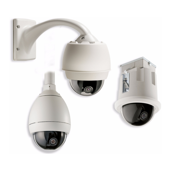
- Page 1 AutoDome 100 Series Fixed Camera AutoDome 100 Series Installation Manual...
-
Page 3: Table Of Contents
Wiring for Multiple AutoDomes 3.7.2 Connecting Wires to the Pipe Interface Board Attach Pendant to Pipe and Tighten Make Connections in the Power Supply Box 3.9.1 Connections for Fiber Optic Models Bosch Security Systems, Inc. Installation Manual F.01U.217.818 | 1.0 | 2011.04... - Page 4 Controlling the AutoDome via the RS485 Protocol Fiber Optic Module with an RS232/RS422 Controller 5.5.1 Connecting to an LTC 4629 Head End Data/Video Transceiver 5.5.2 Configuring the VG5 AutoDome F.01U.217.818 | 1.0 | 2011.04 Installation Manual Bosch Security Systems, Inc.
- Page 5 6.4.1 Configuring a Dry Contact Relay 6.4.2 Configuring an Open Collector Output Bubble Handling and Cleaning Handling Cleaning 7.2.1 Cleaning the Bubble Interior 7.2.2 Cleaning the Bubble Exterior Index Bosch Security Systems, Inc. Installation Manual F.01U.217.818 | 1.0 | 2011.04...
-
Page 6: Safety
ON/OFF switch is in the ON position. The power cord is the main power disconnect device for switching off the voltage for all units. F.01U.217.818 | 1.0 | 2011.04 Installation Manual Bosch Security Systems, Inc. - Page 7 17. Attachments, changes or modifications - Only use attachments/accessories specified by the manufacturer. Any change or modification of the equipment, not expressly approved by Bosch, could void the warranty or, in the case of an authorization agreement, authority to operate the equipment.
-
Page 8: Safety Precautions
-10 °C (14 °F) to 50 °C (122 °F). Camera signal - Protect the cable with a primary protector if the camera signal is beyond 140 feet, in accordance with NEC800 (CEC Section 60). F.01U.217.818 | 1.0 | 2011.04 Installation Manual Bosch Security Systems, Inc. - Page 9 Please dispose of these units at an environmentally compatible recycling facility, per European Directive 2002/96/EC. Environmental statement - Bosch has a strong commitment towards the environment. This unit has been designed to respect the environment as much as possible.
- Page 10 Because the ISDN circuits are treated like telephone-network voltage, avoid connecting the SELV circuit to the Telephone Network Voltage (TNV) circuits. Video loss - Video loss is inherent to digital video recording; therefore, Bosch Security Systems cannot be held liable for any damage that results from missing video information. To minimize the risk of lost digital information, Bosch Security Systems recommends multiple, redundant recording systems, and a procedure to back up all analog and digital information.
- Page 11 UL MAKES NO REPRESENTATIONS, WARRANTIES, OR CERTIFICATIONS WHATSOEVER REGARDING THE PERFORMANCE OR RELIABILITY OF ANY SECURITY OR SIGNALING- RELATED FUNCTIONS OF THIS PRODUCT. Copyright This user guide is the intellectual property of Bosch Security Systems, Inc. and is protected by copyright. All rights reserved. Trademarks All hardware and software product names used in this document are likely to be registered trademarks and must be treated accordingly.
-
Page 12: Customer Support And Service
| Safety AutoDome 100 Series Fixed Camera Customer Support and Service If this unit needs service, contact the nearest Bosch Security Systems Service Center for authorization to return and shipping instructions. Service Centers Telephone: 800-366-2283 or 585-340-4162 Fax: 800-366-1329 Email: [email protected]... -
Page 13: Installing The Pendant Arm Wall, Corner, And Mast (Pole) Mounts
Verify that all the parts listed in the Parts List below are included. If any items are missing, notify your Bosch Security Systems Sales or Customer Service Representative. Refer to Section 1.4 Customer Support and Service, page 12, for contact information. -
Page 14: Description
No. 2 Phillips screwdriver – Socket wrench and 9/16-in. socket – Banding tool (Bosch P/N TC9311PM3T) - if installing a mast (pole) mount – 3/4 in. (20-mm) NPS right angle conduit connector - if installing a mast (pole) mount with a VG4-ARMPLATE... -
Page 15: Mount Power Supply Box
The mounting material must be able to withstand this pull out force. For example, 19-mm (3/4-inch) minimum for plywood. Place the Power Supply Box into the optional Trim Skirt. Bosch Security Systems, Inc. Installation Manual F.01U.217.818 | 1.0 | 2011.04... -
Page 16: Route Wires And Attach Connectors
Mast Plate to the pole. Contact your Bosch Sales Representative to order Banding Tool P/N TC9311PM3T. Secure the Power Supply Box to the Corner Plate or Mast Plate using the four (4) 3/8 x 1-3/4-inch bolts and split lock washers (supplied). -
Page 17: Make The Connections
If “daisy chaining” a series of AutoDomes, a terminating resistor is required in the last dome of the series. The Bosch Power Supply Box is supplied with a 100 Ω terminating resistor located between the Biphase terminals C- and C+ (pins 1 and 2) of the P106 control connector. - Page 18 Connector to the appropriate incoming wires. Refer to Figure 2.3, Page 18, above, for the wire connections. Refer to Section 6 Alarms and Relay Connections, page 69 for more details about wiring alarms and relays. F.01U.217.818 | 1.0 | 2011.04 Installation Manual Bosch Security Systems, Inc.
-
Page 19: Power Supply Box Connections
T 5.0 A T 2.0 A T 3.15 A 115 V T 1.6 A T 2.0 A T 3.15 A 230 V T 0.8A T 2.0 A T 3.15 A Bosch Security Systems, Inc. Installation Manual F.01U.217.818 | 1.0 | 2011.04... -
Page 20: Route Power Through Intermediate Power Supply Box
Figure 2.5 VG4-PSU1/VG4-PSU2 Power Supply Box 120/230 VAC Power In Transformer Ground Wire In/Out Conduit (1/2 in. [15 mm] NPS Fitting P101 Connector 24 VAC Power Out to VG4-PA0 P107 Connector F.01U.217.818 | 1.0 | 2011.04 Installation Manual Bosch Security Systems, Inc. - Page 21 Ensure that you connect the outgoing power supply wires to the P107 heater connectors (HN and HL). The heater power (XF103) fuse can handle a higher amperage (3.15 A) than the camera power (XF102) fuse (2.0 A). Bosch Security Systems, Inc. Installation Manual F.01U.217.818 | 1.0 | 2011.04...
- Page 22 3 P101 Connector 4 Control Data and Video In/Out Wires Follow the instructions in Section 2.6 Attach Pendant Arm to Power Supply Box, page 23, to continue the installation. F.01U.217.818 | 1.0 | 2011.04 Installation Manual Bosch Security Systems, Inc.
-
Page 23: Attach Pendant Arm To Power Supply Box
Serious injury or death can occur if the hinge pins of the Pendant Arm are not fully engaged (locked) to the Power Supply Box. Exercise caution before releasing the Pendant Arm. Bosch Security Systems, Inc. Installation Manual F.01U.217.818 | 1.0 | 2011.04... -
Page 24: Make Connections In Power Supply Box
24 VAC Power UTP Video/Ethernet (Ethernet for VG5 700 Series only) Alarm Inputs Alarm Outputs Relays Grounding Strap WARNING! Do not connect the RJ45 connector unless using UTP video or Ethernet. F.01U.217.818 | 1.0 | 2011.04 Installation Manual Bosch Security Systems, Inc. - Page 25 24V NC GND TXD RXD C+ C- Figure 2.11 Optional Fiber Optic Module Transformer In/Out BNC to Dome ST Connector (Fiber) In/Out Power In From Arm Harness Data In/Out Bosch Security Systems, Inc. Installation Manual F.01U.217.818 | 1.0 | 2011.04...
-
Page 26: Installing The Vg4-A-Armplate
Follow the instructions provided with the banding tool to securely mount the Mast Plate to the pole. Contact your Bosch Sales Representative to order Banding Tool P/N TC9311PM3T. -
Page 27: Attach The Pendant Arm To The Mounting Plate
Mounting Plate. Compress the bottom hinge pin by pushing the pin lever downward and rotating it behind the Hinge Pin Stop. Figure 2.12 Connect Pendant Arm to Mounting Plate Bosch Security Systems, Inc. Installation Manual F.01U.217.818 | 1.0 | 2011.04... -
Page 28: Route And Connect Wires To A Power Supply Box
Grounding Strap (black) UTP Video/Ethernet (blue) (Ethernet for VG5 700 Series only) 24 VAC Power (red) Alarm Outputs (white) Relay Contacts (yellow) Alarm Inputs (gray) Coax Video (black) Serial Communications (green) F.01U.217.818 | 1.0 | 2011.04 Installation Manual Bosch Security Systems, Inc. - Page 29 Note: Do not connect the RJ45 connector unless using UTP video. 10. Connect the incoming video coax cable to the BNC connector (cable 4) and slide its plastic cover over the connector. Bosch Security Systems, Inc. Installation Manual F.01U.217.818 | 1.0 | 2011.04...
- Page 30 (2) captive screws to 10-12 N-m (90-105 in.-lbs). NOTICE! After all wiring is complete, close the cover door and tighten the two (2) captive screws on the cover door to 10-12 N-m (90-105 in.-lbs). F.01U.217.818 | 1.0 | 2011.04 Installation Manual Bosch Security Systems, Inc.
-
Page 31: Attach Pendant To Arm And Tighten
Hook and drop. 2a Recessed Hinge Pin 2b Dome Connector Rotate down to engage dome connector. Tighten the two (2) mounting screws to a minimum torque of 10-12 N-m (90-105 in.-lbs). Bosch Security Systems, Inc. Installation Manual F.01U.217.818 | 1.0 | 2011.04... - Page 32 10-12 N-m (90-105 in.-lbs). CAUTION! You must tighten the two mounting screws to a minimum torque of 10-12 N-m (90-105 in.-lbs) to ensure a proper seal between the arm and the housing. F.01U.217.818 | 1.0 | 2011.04 Installation Manual Bosch Security Systems, Inc.
-
Page 33: Installing Roof Parapet And Pipe Mounts
The VG4-A-9230 Series are stationary mounts intended for rooftop parapet vertical walls. They are made of light weight aluminum with a corrosion-resistant finish and are used for all Bosch AutoDome Cameras up to a rated load of 29 kg (64 lb). These mounts can be fitted to the inside or outside of parapet walls and can swivel for ease of positioning and for servicing the AutoDome. -
Page 34: Tools Required
Choose the appropriate mounting kit to use depending on the location of the AutoDome: Parapet (Roof) mount or the Pipe mount. CAUTION! Select a rigid mounting location to prevent excessive vibration to the AutoDome camera. F.01U.217.818 | 1.0 | 2011.04 Installation Manual Bosch Security Systems, Inc. -
Page 35: Mount Power Supply Box
Attach the 3/4 in. (20 mm) watertight pipe fittings (not supplied) to the holes of the Power Supply Box through which you will run the power, video, and control data wires. Bosch Security Systems, Inc. Installation Manual F.01U.217.818 | 1.0 | 2011.04... -
Page 36: Attach Cover Door
NOTICE! After all wiring is complete, close the cover door and tighten the two (2) captive screws on the cover door to 10-12 N-m (90-105 in.-lbs) to ensure the Power Supply Box is watertight. F.01U.217.818 | 1.0 | 2011.04 Installation Manual Bosch Security Systems, Inc. -
Page 37: Route Wires And Attach Connectors
120 VAC/230 VAC Power In Coax, UTP Video, or Ethernet Wire (Ethernet for VG5 700 Series only) P101 Connector Control Wire Ground Connection 24 VAC Power Out Transformer P107 Connector Bosch Security Systems, Inc. Installation Manual F.01U.217.818 | 1.0 | 2011.04... - Page 38 Heater Power NOTICE! Fiber Optic Models require that the Biphase control wires be routed from the Power Supply Box P106 connector out to the Pipe Interface Board P105 connector. F.01U.217.818 | 1.0 | 2011.04 Installation Manual Bosch Security Systems, Inc.
-
Page 39: Wiring The Power Supply Box
Route the control wires from the Power Supply to the Pipe Interface Board. Then attach the supplied six (6) pin control data connector to the wires in the Power Supply Box. Bosch Security Systems, Inc. Installation Manual F.01U.217.818 | 1.0 | 2011.04... - Page 40 AutoDome 100 Series Fixed Camera (GND) NC 24V GND TXD RXD C+ C- Transformer In/Out BNC to Dome ST Connector (Fiber) In/Out Power In From Arm Harness Data In/Out F.01U.217.818 | 1.0 | 2011.04 Installation Manual Bosch Security Systems, Inc.
-
Page 41: Power Supply Box Connections
T 5.0 A T 2.0 A T 3.15 A 115 V T 1.6 A T 2.0 A T 3.15 A 230 V T 0.8A T 2.0 A T 3.15 A Bosch Security Systems, Inc. Installation Manual F.01U.217.818 | 1.0 | 2011.04... -
Page 42: Installing The Vg4-A-9230 Roof Parapet Mount
Parapet arm for the AutoDome to clear the top of the wall when it is swung into position. Provide enough slack in the wires to rotate the pipe arm over the roof and back when camera maintenance is required. F.01U.217.818 | 1.0 | 2011.04 Installation Manual Bosch Security Systems, Inc. - Page 43 LTC 9230/01 Roof Mount Plate to the roof and then attach the Parapet Wall Bracket to the Roof Mount Plate. Insert the Parapet Pipe Arm into the mounting bracket until it bottoms in the bracket. Bosch Security Systems, Inc. Installation Manual F.01U.217.818 | 1.0 | 2011.04...
- Page 44 You must thread the Dome Cap onto the Down Pipe until it is tight. Failure to do so can result in damage, serious injury, or death. Figure 3.8 Attach Dome Cap Thread Sealant or tape Dome Cap F.01U.217.818 | 1.0 | 2011.04 Installation Manual Bosch Security Systems, Inc.
-
Page 45: Installing The Vg4-A-9543 Pipe Mount
Route the power, video, control, and alarm wires through the Top-Mounting Flange and down the pipe. Wrap at least five layers of Teflon tape around the threads. Bosch Security Systems, Inc. Installation Manual F.01U.217.818 | 1.0 | 2011.04... -
Page 46: Wire The Pipe Interface Board
Board, as illustrated below. Refer to Section 5 Cable and Wire Standards, page 61 for cable and wiring recommendations and specifications. AGND OUT 3 OUT 2 OUT 1 Figure 3.10 Pipe Interface Board Connections F.01U.217.818 | 1.0 | 2011.04 Installation Manual Bosch Security Systems, Inc. -
Page 47: Wiring For Multiple Autodomes
C- terminals to the RxD+ and TxD- terminals (pins 4 and 5) of the P105 control connector for the last dome (refer to item 6 in Figure 3.10 above). Bosch Security Systems, Inc. Installation Manual F.01U.217.818 | 1.0 | 2011.04... -
Page 48: Connecting Wires To The Pipe Interface Board
Alarm Out 3‡ Alarm In 5 Alarm Out 4 Normally Closed Alarm Ground Alarm In 6 Earth Ground Alarm In 7 Analog Alarm 1 Alarm Ground Analog Alarm 2 Ground F.01U.217.818 | 1.0 | 2011.04 Installation Manual Bosch Security Systems, Inc. - Page 49 Be careful not to strip the threads when tightening the Pipe Interface Board retaining screws. Figure 3.12 Pipe Interface Board to Dome Cap Assembly Interface Board Retaining Screws (3) Pendant Mounting Screws (2) Bosch Security Systems, Inc. Installation Manual F.01U.217.818 | 1.0 | 2011.04...
-
Page 50: Attach Pendant To Pipe And Tighten
2a Dome Cap 2b Recessed Hinge Pin Dome Connector Rotate down to engage dome connector Tighten the two (2) mounting screws to a minimum torque of 10-12 N-m (90-105 in.-lbs) F.01U.217.818 | 1.0 | 2011.04 Installation Manual Bosch Security Systems, Inc. -
Page 51: Make Connections In The Power Supply Box
BNC connector of the Fiber Optic Module. Connect the six (6) control plugs from the dome, installed previously, to the P106 control I/O connector in the Power Supply Box. Bosch Security Systems, Inc. Installation Manual F.01U.217.818 | 1.0 | 2011.04... -
Page 52: Installing The In-Ceiling Mount
Verify that all the parts listed in the product's Parts List below are included. If any items are missing, notify your Bosch Security Systems Sales or Customer Service Representative. Refer to Section 1.4 Customer Support and Service, page 12, for contact information. -
Page 53: Dimensions
(177.8 mm ±2.2 mm) hole in the ceiling with a drywall utility saw or Jig Saw. Proceed to Section 4.6 Wire the Interface Box, page 55, for further instructions. Bosch Security Systems, Inc. Installation Manual F.01U.217.818 | 1.0 | 2011.04... -
Page 54: Prepare Suspension Ceiling For Installation
Use the bracket Base Plate as a template or cut a 7 in. hole with a tolerance of ±1/8 in. (177.8 mm ±2.2 mm) hole in the center of the ceiling tile with a drywall utility saw or Jig Saw. Figure 4.3 Cut Hole in Ceiling Tile F.01U.217.818 | 1.0 | 2011.04 Installation Manual Bosch Security Systems, Inc. -
Page 55: Wire The Interface Box
The Interface Box can be wired through the top or side. Use the supplied rubber plug to seal the hole which will not be used to route wires. Figure 4.6 Interface Box Connections Bosch Security Systems, Inc. Installation Manual F.01U.217.818 | 1.0 | 2011.04... -
Page 56: Make The Connections
Normally Closed Alarm Ground Alarm In 6 Earth Ground Alarm In 7 Analog Alarm 1 Alarm Ground Analog Alarm 2 * Low Voltage TTL (3.3V) can also be used. Ground F.01U.217.818 | 1.0 | 2011.04 Installation Manual Bosch Security Systems, Inc. -
Page 57: Interface Box Connections
The following figure is a detailed illustration of the In-ceiling Interface box. Figure 4.8 In-ceiling Interface Box Fiber Optics Coax Video UTP/Ethernet Video Alarm In (Ethernet for VG5 700 Series only) Dome Power Analog In Data In/Out Relay Bosch Security Systems, Inc. Installation Manual F.01U.217.818 | 1.0 | 2011.04... -
Page 58: Attach Housing To The Interface Box
Insert the In-ceiling housing through the hole in the ceiling to verify that the edge of the hole support the unit. Then remove the housing from the hole. Align the ball studs of the In-Ceiling Housing to the Stud Retainers on Interface Box and attach. F.01U.217.818 | 1.0 | 2011.04 Installation Manual Bosch Security Systems, Inc. - Page 59 Figure 4.11, Page 60, below for an illustration of this process. Bosch Security Systems, Inc. Installation Manual...
-
Page 60: Secure Housing To Ceiling
Over torquing the Ceiling Clamps can damage the clamp or ceiling. Only tighten the clamp until it contacts the ceiling and you start to feel some resistance. If using a power screwdriver, set the torque level to the lowest setting. F.01U.217.818 | 1.0 | 2011.04 Installation Manual Bosch Security Systems, Inc. -
Page 61: Cable And Wire Standards
Bilinx control data can also be sent over the same cable. Bilinx is a Bosch 2-way communication protocol that allows remote control, configuration, and updates over a video coax cable. Bilinx is available on all VG5 100 and 600 Series AutoDomes. -
Page 62: Using Utp To Transmit Video And Control
Bilinx control data can also be sent over the same two video wires (1 & 2). Bilinx is a Bosch 2- way communication protocol that allows remote control, configuration and updates over a passive UTP cable. -
Page 63: Control-Only Cables
Controlling the AutoDome via Biphase (Shielded 2-wire, half-duplex, multi-drop, 5000 ft. cable limit) Biphase is the standard Bosch protocol used to send Pan/Tilt/Zoom control over 2-wire shielded twisted pair (STP) terminated with a 100 Ω terminal resistor. The AutoDome has a 100 Ω termination resistor between the Biphase C+ and C- terminals. -
Page 64: Controlling The Autodome Via The Rs232 Protocol
Wire Type 3-wire (TXD, RXD, common) Distance 15 m (50 ft) Maximum Baud Rate 57.6 Kb Voltage ± 15 V Termination 100 Ω Slide Switch Away from LEDs (factory default) F.01U.217.818 | 1.0 | 2011.04 Installation Manual Bosch Security Systems, Inc. -
Page 65: Controlling The Autodome Via The Rs485 Protocol
The wire shield must be tied to signal at both ends, if 2-wire twisted pair is used. After connecting the wires for RS485 operation, make sure the slide switch on the main board to the camera head is positioned toward the LEDs (default). Bosch Security Systems, Inc. Installation Manual F.01U.217.818 | 1.0 | 2011.04... - Page 66 AutoDome 100 Series Fixed Camera CAUTION! Bosch recommends that multiple RS485 connections be arranged as a connected series of point-to-point (multi-dropped) nodes, as a line or as a bus. It is not recommended to arrange RS485 connections as a star, ring, or as a multiple-connected network. Star and ring topologies may cause signal reflections or excessively low or high termination impedance.
-
Page 67: Fiber Optic Module With An Rs232/Rs422 Controller
Green RxD wire connected to C+ Blue Ground wire connected to C- Connect the fiber optic cable from the AutoDome to the LTC 4629. Close the door to the power supply unit. Bosch Security Systems, Inc. Installation Manual F.01U.217.818 | 1.0 | 2011.04... - Page 68 Switch Location LEDs Move Switch to the left for RS232 Operation CPU Module 11. Return the bubble to the AutoDome housing. 12. Return power to the power supply box. F.01U.217.818 | 1.0 | 2011.04 Installation Manual Bosch Security Systems, Inc.
-
Page 69: Alarms And Relay Connections
Connect the alarm wires to input 1 or 2 (pin 5 or 6) and to the ground (pin 7) at the AutoDome. 2.2K Figure 6.1 N.O.S. - Normally Open Supervised Connections Dry Contact Dome Connector Alarm 1 or 2 only (Pin 5 or 6) Ground (Pin 7) Bosch Security Systems, Inc. Installation Manual F.01U.217.818 | 1.0 | 2011.04... -
Page 70: Configuring A Normally Closed Supervised Alarm
Alarm Closed Normal Short Tamper Configuring Non-supervised Alarms (inputs 1 through 7) You can configure alarms 3 through 7 as non-supervised Normally Open (N.O.) or Normally Closed (N.C.) alarms. F.01U.217.818 | 1.0 | 2011.04 Installation Manual Bosch Security Systems, Inc. -
Page 71: Configuring A Normally Open Non-Supervised Alarm
From the AutoDome main menu select Alarm Setup>Inputs Setup, and set Alarm Input # to N.C. See the table below for contact and condition details. AutoDome Programmed N.C. Circuit Alarm Indication Open Alarm Closed Normal Bosch Security Systems, Inc. Installation Manual F.01U.217.818 | 1.0 | 2011.04... -
Page 72: Alarm Outputs
@ 150 ma. Connect the appropriate stripped wire to the open connector (1, 2, or 3) of the transistor. Connect the appropriate stripped wire to the ground (GND) connector. F.01U.217.818 | 1.0 | 2011.04 Installation Manual Bosch Security Systems, Inc. -
Page 73: Bubble Handling And Cleaning
Figure 7.1 Pendant Bubble Release Opening Firmly rotate the bubble counterclockwise approximately 20 degrees until the bubble assembly releases from the Pendant Housing. Bosch Security Systems, Inc. Installation Manual F.01U.217.818 | 1.0 | 2011.04... -
Page 74: Cleaning The Bubble Exterior
Do Not scrape the bubble with razor blades or other sharp instruments. – Do Not use Benzene, Gasoline, Acetone, or Carbon Tetrachloride on the bubble. – Do Not clean bubbles in the hot sun or on very hot days. F.01U.217.818 | 1.0 | 2011.04 Installation Manual Bosch Security Systems, Inc. -
Page 75: Index
34 copper wire 61 non-supervised alarms 70 corner installation 16 corner plate 16 cover door 36 daisy chaining 17 dome cap 44 drywall ceiling 53 Ethernet 56 F.01U.217.818 | 1.0 | 2011.04 Installation Manual Bosch Security Systems, Inc. - Page 76 55 for pendant arm, corner or mast mount 16 for roof parapet or pipe mount 37 RS232 64 RS485 65 supervised 69 suspension ceiling 54 Bosch Security Systems, Inc. Installation Manual F.01U.217.818 | 1.0 | 2011.04...
- Page 77 | Index AutoDome 100 Series Fixed Camera F.01U.217.818 | 1.0 | 2011.04 Installation Manual Bosch Security Systems, Inc.
- Page 80 Bosch Security Systems, Inc. 850 Greenfield Road Lancaster, PA 17601 U.S.A. www.boschsecurity.com © Bosch Security Systems, Inc., 2011...