Table of Contents
Quick Links
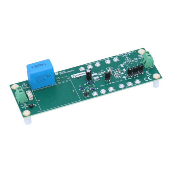
This user's guide describes the operational use of the TPS7A78EVM-011 evaluation module (EVM) as a
reference design for engineering demonstration and evaluation of the TPS7A78, non-isolated smart linear
voltage regulator (LDO). Included in this user's guide are setup and operating instructions, thermal and
layout guidelines, a printed circuit board (PCB) layout, a schematic diagram, and a bill of materials (BOM).
Throughout this document, the terms demonstration kit, evaluation board, and evaluation module are
synonymous with the TPS7A78EVM-011.
The following related documents are available through the Texas Instruments web site at www.ti.com.
SBVU048 – March 2019
Submit Documentation Feedback
All manuals and user guides at all-guides.com
TPS7A78EVM-011 Evaluation module
Table 1. Related Documentation
Device
TPS7A78
Copyright © 2019, Texas Instruments Incorporated
Literature Number
SBVS343
TPS7A78EVM-011 Evaluation module
User's Guide
SBVU048 – March 2019
1
Table of Contents

Related Manuals for Texas Instruments TPS7A78


Summary of Contents for Texas Instruments TPS7A78
-
Page 1: Related Documentation
This user’s guide describes the operational use of the TPS7A78EVM-011 evaluation module (EVM) as a reference design for engineering demonstration and evaluation of the TPS7A78, non-isolated smart linear voltage regulator (LDO). Included in this user’s guide are setup and operating instructions, thermal and layout guidelines, a printed circuit board (PCB) layout, a schematic diagram, and a bill of materials (BOM). -
Page 2: Table Of Contents
All manuals and user guides at all-guides.com General Texas Instruments High Voltage Evaluation (TI HV EVM) User Safety Guidelines www.ti.com Contents ...... General Texas Instruments High Voltage Evaluation (TI HV EVM) User Safety Guidelines ........................Introduction ..................Electrical Performance Specifications ........................ - Page 3 Any other use and/or application are strictly prohibited by Texas Instruments. If you are not suitable qualified, you should immediately stop from further use of the HV EVM.
-
Page 4: Introduction
Texas Instruments' TPS7A78EVM-011 helps design engineers evaluate the operation and performance of the TPS7A78 smart linear voltage regulator for possible use in their own circuit application. This particular EVM is intended for evaluation purposes and is not intended to be an end product. The EVM configuration contains a single 3.3-V output regulator optimized for e-metering applications. -
Page 5: Electrical Performance Specifications
270 VRMS 2.5 A 50/60 Hz Neutral AC N PF_S EXT Pull-up TP11 LDO_IN PG_S SN74LVC2G07DBVR 100k 100k PF_S PG_S Figure 1. TPS7A78EVM-011 Schematic SBVU048 – March 2019 TPS7A78EVM-011 Evaluation module Submit Documentation Feedback Copyright © 2019, Texas Instruments Incorporated... -
Page 6: Evm Setup
TPS7A78 LDO. NOTE: If the AC supply line and neutral leads are flipped when connected to the J1 connector, then the TPS7A78 device GND pin is referenced to the AC supply line and only floating measurement equipment must be used. -
Page 7: Test Point Functions
5.1.5 J6 and J7: Power-Good (PG) and Power-Fail (PF) Signals The TPS7A78 device has two open-drain signals (power-good and power-fail) that are both pulled up to by default. LDO_IN Becuase of the high-impedance open-drain logic, the AC supply frequency noise may be present on those signals when they are high. -
Page 8: Ac Half-Bridge (Hb) And 27-Ma Load Current
Description section for details on the device active bridge control. Figure 6 shows the PF signal glitch. LDO_OUT AC_P Time (ms) Figure 6. PF Signal Glitch TPS7A78EVM-011 Evaluation module SBVU048 – March 2019 Submit Documentation Feedback Copyright © 2019, Texas Instruments Incorporated... -
Page 9: Equipment Connection And Operation
Equipment Connection Connect test equipment as described in this section and follow the listed steps to properly take measurements: NOTE: The FB configuration for the EVM requires a differential measurement. The TPS7A78 device GND must not be tied to Earth-GND. 6.1.1... -
Page 10: Proper Test Equipment Connections For The Half-Bridge (Hb) Evm Configuration
Operate the test equipment using the following steps: 1. Turn on the AC power supply. 2. Vary the respective load and input voltage, as necessary, for test purposes. TPS7A78EVM-011 Evaluation module SBVU048 – March 2019 Submit Documentation Feedback Copyright © 2019, Texas Instruments Incorporated... -
Page 11: Pcb Layout
PCB layout for this EVM. Figure 9. Assembly Layer NOTE: The silk screens for resistors R1 and R2 are flipped in Figure Figure 10. Top Layer Routing SBVU048 – March 2019 TPS7A78EVM-011 Evaluation module Submit Documentation Feedback Copyright © 2019, Texas Instruments Incorporated... -
Page 12: Bottom Layer Routing
All manuals and user guides at all-guides.com PCB Layout www.ti.com Figure 11. Bottom Layer Routing TPS7A78EVM-011 Evaluation module SBVU048 – March 2019 Submit Documentation Feedback Copyright © 2019, Texas Instruments Incorporated... -
Page 13: Bill Of Materials (Bom)
These assemblies must comply with workmanship standards IPC-A-610 Class 2. Unless otherwise noted in the Alternate Part Number or Alternate Manufacturer columns, all parts may be substituted with equivalents. SBVU048 – March 2019 TPS7A78EVM-011 Evaluation module Submit Documentation Feedback Copyright © 2019, Texas Instruments Incorporated... - Page 14 All manuals and user guides at all-guides.com STANDARD TERMS FOR EVALUATION MODULES Delivery: TI delivers TI evaluation boards, kits, or modules, including any accompanying demonstration software, components, and/or documentation which may be provided together or separately (collectively, an “EVM” or “EVMs”) to the User (“User”) in accordance with the terms set forth herein.
- Page 15 All manuals and user guides at all-guides.com www.ti.com Regulatory Notices: 3.1 United States 3.1.1 Notice applicable to EVMs not FCC-Approved: FCC NOTICE: This kit is designed to allow product developers to evaluate electronic components, circuitry, or software associated with the kit to determine whether to incorporate such items in a finished product and software developers to write software applications for use with the end product.
- Page 16 All manuals and user guides at all-guides.com www.ti.com Concernant les EVMs avec antennes détachables Conformément à la réglementation d'Industrie Canada, le présent émetteur radio peut fonctionner avec une antenne d'un type et d'un gain maximal (ou inférieur) approuvé pour l'émetteur par Industrie Canada. Dans le but de réduire les risques de brouillage radioélectrique à...
- Page 17 All manuals and user guides at all-guides.com www.ti.com EVM Use Restrictions and Warnings: 4.1 EVMS ARE NOT FOR USE IN FUNCTIONAL SAFETY AND/OR SAFETY CRITICAL EVALUATIONS, INCLUDING BUT NOT LIMITED TO EVALUATIONS OF LIFE SUPPORT APPLICATIONS. 4.2 User must read and apply the user guide and other available documentation provided by TI regarding the EVM prior to handling or using the EVM, including without limitation any warning or restriction notices.
- Page 18 Notwithstanding the foregoing, any judgment may be enforced in any United States or foreign court, and TI may seek injunctive relief in any United States or foreign court. Mailing Address: Texas Instruments, Post Office Box 655303, Dallas, Texas 75265 Copyright © 2019, Texas Instruments Incorporated...
- Page 19 TI products. TI’s provision of these resources does not expand or otherwise alter TI’s applicable warranties or warranty disclaimers for TI products. Mailing Address: Texas Instruments, Post Office Box 655303, Dallas, Texas 75265 Copyright © 2019, Texas Instruments Incorporated...