
Related Manuals for GE Ericsson LBI-38977C


Summary of Contents for GE Ericsson LBI-38977C
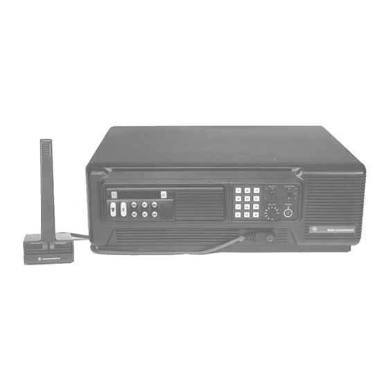
- Page 1 LBI-38977C Mobile Communications MDX/ORION Desk Top Station Printed in U.S.A Installation Manual...
-
Page 2: Unpacking And Checking Equipment
The unused material was shipped with the station. Re- ferent current capabilities. Refer to the applicable power su- dio. move the kit and store for possible use. ply maintenance manual for current usage. Copyright© September 1993, Ericsson GE Mobile Communications Inc. - Page 3 LBI-38977 If the Desk Top Assembly already includes the factory Receive Audio (R2) (R35) (R66) installed "Intercom Remote" Control Panel and the Remote Interface Board, proceed to Step 6 below. 1. Apply a 1000 Hz tone with a 3 kHz deviation to the sta- Otherwise, replace the standard Control Panel with tion receiver that is strong enough to fully quiet the receiver.
-
Page 4: Speaker Level
LBI-38977 Remove the four (4) screws securing the Control If the calibration must be changed, a calibration mode is en- Speaker Level VU METER TEST/CALIBRATION Panel. tered by removing power from the unit, then while holding down SW1, powering the unit. The unit will display a 3 digit After the Remote Board is set up so that the remote Remove P106 from the Power LED, note polarity. -
Page 5: Mobile Installation
LBI-38977 INSTALLATION INSTRUCTIONS APPLICATION ASSEMBLY Mobile Installation (19D904704, Sh. 1, Rev. 3A) - Page 6 INSTALLATION INSTRUCTIONS LBI-38977 APPLICATION ASSEMBLY Mobile Installation (Cont’d from Sh.1) (19D904704, Sh. 2, Rev. 2A)
- Page 7 LBI-38977 INSTALLATION INSTRUCTIONS APPLICATION ASSEMBLY MDX Local with Keypad (19D904704, Sh. 3, Rev. 2)
- Page 8 INSTALLATION INSTRUCTIONS LBI-38977 APPLICATION ASSEMBLY Local/ DC Remote (19D904704, Sh. 4, Rev. 2A)
- Page 9 LBI-38977 INSTALLATION INSTRUCTIONS APPLICATION ASSEMBLY MDX Local/DC Remote with Keypad (19D904704, Sh. 5, Rev. 2)
- Page 10 INSTALLATION INSTRUCTIONS LBI-38977 APPLICATION ASSEMBLY MDX Local/Tone Remote (19D904704, Sh. 6, Rev. 2A)
- Page 11 LBI-38977 INSTALLATION INSTRUCTIONS APPLICATION ASSEMBLY MDX Local/Tone Remote with Keypad (19D904704, Sh. 7, Rev. 2)
- Page 12 INSTALLATION INSTRUCTIONS LBI-38977 APPLICATION ASSEMBLY EDACS MDX Local/Remote with Keypad (19D904704, Sh. 8, Rev. 2)
- Page 13 LBI-38977 INSTALLATION INSTRUCTIONS APPLICATION ASSEMBLY Local with Clock (19D904704, Sh. 9, Rev. 3A)
- Page 14 INSTALLATION INSTRUCTIONS LBI-38977 APPLICATION ASSEMBLY Local/DC Remote with Clock (19D904704, Sh. 10, Rev. 3A)
- Page 15 LBI-38977 INSTALLATION INSTRUCTIONS APPLICATION ASSEMBLY Local/Tone Remote with Clock VU (19D904704, Sh. 11, Rev. 3A)
- Page 16 INSTALLATION INSTRUCTIONS LBI-38977 APPLICATION ASSEMBLY Battery Power Transfer Option (19D904704, Sh. 12, Rev. 3A)
- Page 17 LBI-38977 INSTALLATION INSTRUCTIONS APPLICATION ASSEMBLY ORION Mobile Installation (19D904704, Sh. 13, Rev. 3A)
- Page 18 INTERCONNECTION DIAGRAM LBI-38977 MDX RADIO APPLICATION Interconnect Board & Power Supply (19D904375, Sh. 1, Rev. 1)
- Page 19 LBI-38977 INTERCONNECTION DIAGRAM MDX RADIO APPLICATION Remote Interface Board Option, DC or Tone Remote Option, and Keypad/Frequency Select Option (19D904375, Sh. 2, Rev. 0)
- Page 20 INTERCONNECTION DIAGRAM LBI-38977 MDX RADIO APPLICATION Battery Power Transfer Option (19D904375, Sh. 3, Rev. 1)
- Page 21 LBI-38977 INTERCONNECTION DIAGRAM ORION RADIO APPLICATION Interconnect Board & Power Supply (188D5407, Sh. 1, Rev. 0)
- Page 22 INTERCONNECTION DIAGRAM LBI-38977 ORION RADIO APPLICATION Remote Interface Board Option, DC or Tone Remote Option and Frequency Select Option (188D5407, Sh. 2, Rev. 0...
- Page 23 LBI-38977 INTERCONNECTION DIAGRAM ORION RADIO APPLICATION Battery Power Transfer, Clock/VU Meter Option and Desktop Microphone (188D5407, Sh. 3, Rev. 0)
- Page 24 LBI-38977 This page intentionally left blank...