Table of Contents
Quick Links
AJ*072LALDH
AJ*090LALDH
AJ*108LALDH
AJ*126LALDH
AJ*144LALDH
TM
INSTALLATION MANUAL
INSTALLATIONSANLEITUNG
MANUEL D'INSTALLATION
MANUAL DE INSTALACIÓN
Únicamente para personal de servicio autorizado.
MANUALE DI INSTALLAZIONE
A uso esclusivo del personale tecnico autorizzato.
MANUAL DE INSTALAÇÃO
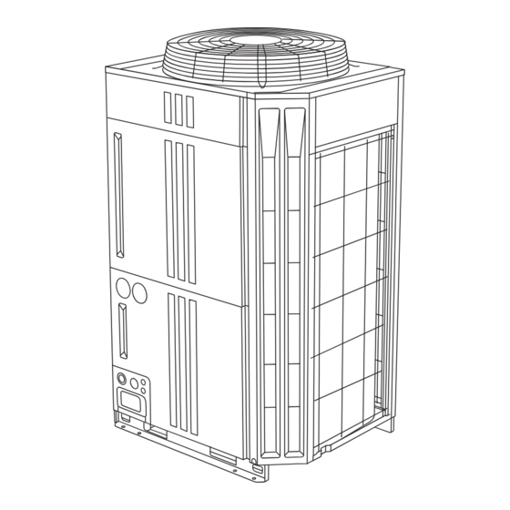
OUTDOOR UNIT
For authorized service personnel only.
Nur für autorisiertes Fachpersonal.
UNITÉ EXTÉRIEURE
Pour le personnel agréé uniquement.
UNIDAD EXTERIOR
UNITÀ ESTERNA
UNIDADE EXTERIOR
Apenas para técnicos autorizados.
MONTAJ KILAVUZU
Yaln ca yetkili servis personeli için.
PART No. 9378945708-03
AUßENGERÄT
.
.
DI
TE
Table of Contents

Related Manuals for Fujitsu AIRSTAGE AJ 072LALDH Series


Summary of Contents for Fujitsu AIRSTAGE AJ 072LALDH Series
- Page 1 INSTALLATION MANUAL OUTDOOR UNIT For authorized service personnel only. INSTALLATIONSANLEITUNG AUßENGERÄT Nur für autorisiertes Fachpersonal. MANUEL D’INSTALLATION UNITÉ EXTÉRIEURE Pour le personnel agréé uniquement. AJ*072LALDH MANUAL DE INSTALACIÓN AJ*090LALDH AJ*108LALDH UNIDAD EXTERIOR AJ*126LALDH Únicamente para personal de servicio autorizado. AJ*144LALDH MANUALE DI INSTALLAZIONE UNITÀ...
-
Page 2: Table Of Contents
INSTALLATION MANUAL [Original instructions] 1. SAFETY PRECAUTIONS PART No. 9378945708-03 VRF system outdoor unit • Be sure to read this Installation manual thoroughly before installation. • The warnings and precautions indicated in this Installation manual contain important information pertaining to your safety. Be sure to observe them. •... -
Page 3: About This Product
This mark indicates procedures which, if improperly per- 2.2. Special tools for R410A CAUTION formed, might possibly result in personal harm to the user, or damage to property. Tool name Contents of change for R22 tool This unit must be installed by qualified personnel with a capacity certificate for handling Pressure is huge and cannot be measured with a conventional gauge. -
Page 4: Optional Parts
Energy-saving combination CAUTION Combination (HP) Select an installation location by observing the following precautions: Outdoor Unit 1 (HP) ― ― ― ― ― ― Outdoor Unit 2 (HP) ― ― ― ― ― ― Install the unit level. (Within 3 degrees) Outdoor Unit 3 (HP) ―... - Page 5 3.3.1 When install nearby limited height wall Unit: mm (1) Single and multiple installations • There are no restrictions on the height of the side wall. • Provide installation spaces L1 and L2 in accordance with the table below according to the wall height (front side, rear side) conditions.
-
Page 6: Transporting The Unit
When installing with the FRONT of the outdoor unit facing the wall side 3.3.3 When there are obstacles above the product When there are obstacles above the product, keep the Unit: mm minimum installation height as shown in the figure and install the outlet duct. -
Page 7: System Configuration
• To minimize vibration, do not install the outdoor unit directly on the ground. 4.1.2 In case of 2 outdoor units connected Instead, install it on top of a firm platform (such as concrete block). (Fig. B) (Subordinate) • The foundation base should be able to support the product and the foot width of the product should be more than 46.5 mm. -
Page 8: Pipe Selection
Table. D (Between separation tube to indoor unit) NOTES: • If the outdoor temperature during cooling operation is expected to be Outside diameter mm (in) Cooling capacity of Model code –5 °C or less, outdoor unit must be installed lower than 5 m or less from the indoor unit. indoor unit (kW) Liquid pipe Gas pipe... -
Page 9: Protection Of Pipes
A (between outdoor unit and outdoor unit branch kit) D (between separation tubes to indoor unit) Allowable pipe Allowable pipe Between primary out door unit and a (+e)+f, Between primary out door unit and a (+e)+f, 70 m or less 120 m or less length (actual pipe length (actual pipe... -
Page 10: Opening The Knockout Hole
Header 5.4. Pipe connection Horizontal line Horizontal line Gas pipe β = 0 to 10 mm CAUTION (α : 0° to 1°) Outdoor α Do not use mineral oil on a flared part. Prevent mineral oil from getting into the system β... -
Page 11: Multiple Connections
Fig. A Branch kit restriction when install Be sure following restriction. (1) Installation angle Install the outdoor unit branch kit horizontally level, within 0° to -10°, so that the refrigerant separates evenly. Joint pipe (Accessory) To indoor unit Joint pipe To outdoor unit Knockout hole (Locally... -
Page 12: Electrical Wiring
(5) Examples of multiple unit installation are shown below. 6. ELECTRICAL WIRING CAUTION 6.1. The precautions of electrical wiring To prevent the oil from settling in the stopped unit, install the pipes between the outdoor units so that they are level or are tilted upward to the outdoor units. WARNING Installable (Primary) -
Page 13: Wiring Method
6.2. Wiring method < Left view > < Front view > 6.2.1 Connection diagrams Ø 50 Ø 50 The wiring example for outdoor units and indoor units is shown in the figure. Ø 34.5 Ø 34.5 To other refrigerant Ø 22.2 Ø... -
Page 14: Transmission Line
6.5. Transmission line NOTES • Unit* means indoor unit, outdoor unit, Touch Panel Controller and System Controller, Signal Amplifier, single split adaptor, Network Convertor etc. CAUTION • Do not use loop wiring. This may lead to parts damage Caution when wiring cable: and erroneous operation. -
Page 15: Wiring Procedure
6.6. Wiring procedure Ring terminal Strip 10 mm • Remove the cover of the electrical compartment and follow the terminal plate to connect the electric cables to the terminal. • After connecting the cables, secure them with the cable ties. Sleeve •... -
Page 16: External Input And External Output
Operation behavior 6.7. External input and external output Each input terminal works as follows. 6.7.1 Terminal position Outdoor unit Input Connector Status Subor- Input 5 Input 4 Input 3 Input 1 Output 1 Output 2 signal Primary dinate Normal operation Input 1 ... -
Page 17: Field Setting
7.2.3 Terminal resistor setting 7. FIELD SETTING CAUTION CAUTION Be sure to set the terminal resistor according to specifications. Discharge the static electricity from your body before setting up the DIP switches. Set the terminal resistor for every network segment (NS). Never touch the terminals or the patterns on the parts that are mounted on the PC If terminal resistor is set in multiple devices, the overall communication system may be board. - Page 18 Normal mode Prohibited (Factory default) Save energy mode Prohibited (Factory default) Cooling capacity High power mode 1 Capacity priority Off (quiet priority) shift (*1) setting (in low High power mode 2 On (capacity priority) noise mode) (*1) Prohibited If the cooling/heating performance becomes insufficient when the low noise mode Set this item when necessary.
-
Page 19: Address Setting For Signal Amplifi Ers
(2) Setting method 7.5. Address setting for signal amplifi ers Use the “MODE/EXIT”, “SELECT”, : Press the “MODE/EXIT” button 7.5.1 Address setting for signal amplifi ers and “ENTER” buttons to configure settings according to the proce- : Press the “SELECT” button When using signal amplifiers, the address for signal amplifiers must be set. -
Page 20: Resistance Measurement Of Transmission Cable (Measure With Breaker Off)
7.6.2 Procedures to enable automatic address setting on indoor 8. PIPE INSTALLATION II units Fig. A Connection system Check that the rotary switch IU AD on the indoor unit PC board is set to “00”.If it is not set to “00”, it means the address of that device is not set. (Factory default is “00”). In case of connected 1 Pressure regulating valve Outdoor unit... -
Page 21: Vacuum Process
8.2. Vacuum process NOTES: • Tighten the body caps and charging caps to the torque values specified in the Table A. To open and close the valves, Use an M4 hexagon wrench for liquid pipe. CAUTION Use an M8 hexagon wrench for suction gas pipe and discharge gas pipe. Do not turn on the power unless all operations are complete. -
Page 22: Installing Insulation
9.2. Test run method When there are 3 outdoor units (AJ*144LALDH, AJ*126LALDH, AJ*108LALDH) connected to 1 system. Be sure to configure test run settings only when the outdoor unit has stopped (1) Calculation of additional amount for outdoor unit. operating. -
Page 23: Checklist
E 7 3. 4 Outdoor unit heat ex. 1 gas temp. sensor error Manufacturer E 7 3. 5 Outdoor unit heat ex. 1 liquid temp. sensor error FUJITSU GENERAL LIMITED (19) Manufacturer E 7 3. 6 Outdoor unit heat ex. 2 gas temp. sensor error...