Table of Contents
Quick Links
TM
INSTALLATION MANUAL
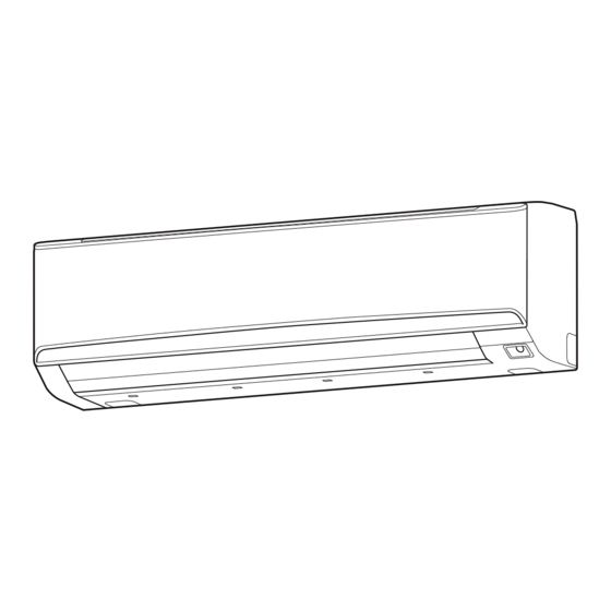
INDOOR UNIT (Wall Mounted Type)
For authorized service personnel only.
MANUEL D'INSTALLATION
UNITÉ INTÉRIEURE (Type montage mural)
ASUA30TLAV2
Pour le personnel agréé uniquement.
ASUA36TLAV2
MANUAL DE INSTALACIÓN
UNIDAD INTERIOR (Tipo montado en pared)
Únicamente para personal de servicio autorizado.
PART No. 9373370475
Table of Contents

Related Manuals for Fujitsu AIRSTAGE ASUA36TLAV2


Summary of Contents for Fujitsu AIRSTAGE ASUA36TLAV2
- Page 1 INSTALLATION MANUAL INDOOR UNIT (Wall Mounted Type) For authorized service personnel only. MANUEL D’INSTALLATION UNITÉ INTÉRIEURE (Type montage mural) ASUA30TLAV2 Pour le personnel agréé uniquement. ASUA36TLAV2 MANUAL DE INSTALACIÓN UNIDAD INTERIOR (Tipo montado en pared) Únicamente para personal de servicio autorizado. PART No.
-
Page 2: Table Of Contents
INSTALLATION MANUAL 1.2. SPECIAL PRECAUTIONS PART No. 9373370475 VRF system indoor unit (Wall mounted type) When Wiring Contents ELECTRICAL SHOCK CAN CAUSE SEVERE PERSONAL INJURY OR DEATH. ONLY A QUALIFIED, EXPERIENCED ELECTRICIAN SHOULD ATTEMPT TO WIRE THIS SYSTEM. 1. SAFETY PRECAUTIONS ....................1 •... -
Page 3: About This Product
2. ABOUT THIS PRODUCT 2.3. Accessories 2.1. Precautions for using R410A refrigerant WARNING For installation purposes, be sure to use the parts supplied by the manufacturer or other WARNING prescribed parts. The use of non-prescribed parts can cause serious accidents such as the unit falling, Do not introduce any substance other than the prescribed refrigerant into the refrigera- water leakage, electric shock, or fire. -
Page 4: Installation Work
3. INSTALLATION WORK 3.2. Installation dimension Wall hook bracket Unit: in (mm) Correct initial installation location is important because it is difficult to move unit after it is Left side 4 (80) or installed. 3 (70) or more more (*1) (*2) 3.1. - Page 5 [For (D) Left bottom piping, (E) Left piping and (F) Center piping, (G) Left rear 3.3.3. Cutting the hole in the wall for the connecting piping piping] (1) Cut a hole in the wall at the position shown in the following. (2) Cut the hole so that the outside end is lower (3/16 to 3/8 in (5 to 10 mm)) than the CAUTION inside end.
-
Page 6: Pipe Installation
4.3.1. Flaring 4. PIPE INSTALLATION Use special flare tool exclusive for R410A. (1) Cut the connection pipe to the necessary length with a pipe cutter. (2) Hold the pipe downward so that cuttings will not enter the pipe and remove any burrs. CAUTION (3) Insert the flare nut (always use the flare nut attached to the indoor and outdoor units Be more careful that foreign matter (oil, water, etc.) does not enter the piping than with... -
Page 7: Electrical Wiring
A. Current breaker requirements 5. ELECTRICAL WIRING • MCA: Minimum Circuit Ampacity MAX. CKT. BKR Model • MAX. CKT. BKR : Maximum Circuit (Fuse capacity) Breaker WARNING ASUA30TLAV2 0.90 A 15 A Electrical work must be performed in accordance with this Manual by a person certified ASUA36TLAV2 1.18 A under the national or regional regulations. -
Page 8: Unit Wiring
5.3.2. Transmission and Remote controller cable 5.3. Unit wiring Transmission cable Remote controller cable • Before attaching the cable to terminal block. 13/16 in (20 mm) 13/16 in (20 mm) 5.3.1. Power supply cable Shield Conduit connector cable (no film) 1-3/8 in (35 mm) Earth... -
Page 9: Optional Parts Wiring
(6) Connect the end of the connection cable fully into the terminal block. 5.5.3. Connection methods Wire modification IMPORTANT: Symbol Connection cable (1) Remove insulation from wire at- Be sure to insulate the connection between the Power supply cable tached to wire kit connector. wires. -
Page 10: External Input And External Output (Optional Parts)
When connected to Dry contact terminals of multiple indoor units with a connected unit, 5.6. External input and external output (optional parts) insulate each indoor unit with relay, etc. as shown on below example. In this setting, you need to remove the front panel. Refer to “8. FRONT PANEL REMOVAL P.C.B AND INSTALLATION”. -
Page 11: Field Setting
Output select 6.1. Setting the address ● When indicator etc. are connected directly P.C.B Manual address setting method The indoor unit address and the refrigerant circuit address can also be set up through the Indicator 1 wireless remote controller CAUTION Indicator 2 Be sure to turn OFF the power before performing the field setting. -
Page 12: Custom Code Setting
Allow an external controller to start 6.2. Custom code setting 00 Start/Stop or stop the system, or to perform Emergency an emergency stop. • Selecting the custom code prevents the indoor unit mix-up. (figure below) stop If an emergency stop is performed (Up to 4 codes can be set.) External from an external controller, all re-... - Page 13 6.3.1. Indoor unit indicator lamps Function Function Setting number Default Details number 00 0°F (0°C) 01 1°F (0.5°C) 02 2°F (1.0°C) 03 3°F (1.5°C) Choose the minimum temperature Deadband 04 4°F (2.0°C) between cooling and heating value (*3) settings (deadband) for Dual 05 5°F (2.5°C) OPERATION indicator lamp (green) setpoint auto mode (set in No.
-
Page 14: Finishing
7. FINISHING 8. FRONT PANEL REMOVAL AND INSTALLATION 8.1. Intake grill removal and installation CAUTION After checking for gas leaks (refer to the Installation Manual of the outdoor unit), perform Intake grill removal Intake grill installation this section. Open the intake While holding the Install heat insulation around both the large (gas) and small (liquid) pipes. -
Page 15: Test Run
9. TEST RUN 11. ERROR CODES If you use a wired type remote controller, error codes will appear on the remote controller 9.1. Test run using Outdoor unit (PCB) display. If you use a wireless remote controller, the lamp on the photodetector unit will output error codes by way of blinking patterns.