Table of Contents
Quick Links
Honeywell Life Safety Iberia
C/Pau Vila 15-19
08911 BADALONA (BARCELONA)
EN12094:1/2003
Tel.: 93 497 39 60 Fax: 93 465 86 35
www.honeywelllifesafety.es
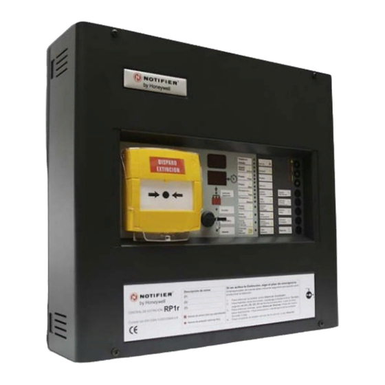
Extinguishing Control Panel
RP1r
3 zone control panel to protect
1 extinguishing risk
User Manual
(Software version 3.x)
MN-DT-102I_J
22 JUNE 2011
Information in this document is subject to change without notice.
Table of Contents

Related Manuals for Honeywell NOTIFIER RP1r


Summary of Contents for Honeywell NOTIFIER RP1r
- Page 1 Honeywell Life Safety Iberia C/Pau Vila 15-19 08911 BADALONA (BARCELONA) EN12094:1/2003 Tel.: 93 497 39 60 Fax: 93 465 86 35 www.honeywelllifesafety.es Extinguishing Control Panel RP1r 3 zone control panel to protect 1 extinguishing risk User Manual (Software version 3.x)
-
Page 3: Table Of Contents
Extinguishing control panel. User manual CONTENTS 1. Introduction............................. 2 1.1 Manual Purpose ..........................2 1.2 Before Installation ..........................2 1.3 System Design and Planning ......................2 1.4. CE Marking............................2 1.5. General.............................. 3 1.6 Release control panel main features ....................4 1.7 Cabling ...............................8 2. -
Page 4: Introduction
Extinguishing control panel. User manual 1. Introduction 1.1 Manual Purpose The purpose of this manual is to provide the user with all recommended procedures and full technical details for the successful installation, commissioning and configuration of extinguishing control panel. This manual must be read, and its contents clearly understood, before proceeding with any work relating to the control panel. -
Page 5: General
Extinguishing control panel. User manual 1.5. General. This release control panel has been designed to manage correctly and according to EN12094:1/2003 and EN54-2 and EN54-4/A2:2006 the automatic release sequence of any extinguishing system. This compact control panel has 2 microprocessors to increase safety and includes a switched 65W power supply with battery charger. -
Page 6: Release Control Panel Main Features
Extinguishing control panel. User manual 1.6 Release control panel main features Compact control panel with double microprocessor. Supply Rating: 90-264Vac 50/60Hz. Total power: 65W (2,4A a 27Vcc). Maximum current supplied by Release control panel: 2,4Amp. 2 monitored sounder outputs (2 x 250mA) ... - Page 7 Extinguishing control panel. User manual ACCESSORIES VSN-LL Keyswitch for level 2 access. PK-RP1r Monitoring software. VSN-232 RS-232 port card. VSN-IP IP Address card (VSN-232 required). VSN-4REL Four relay card. DIMENSIONS (mm): 379 (width) x 356 (height) x 95 (depth). 22 June 2011...
- Page 8 Extinguishing control panel. User manual Front Panel Indications: Extinguishing control panel Conventional control panel EN12094:1/2003 EN54-2/4 22 June 2011...
-
Page 9: Cabling
Extinguishing control panel. User manual 1.7 Cabling Cabling Instructions All wiring should comply with current IEE wiring regulations (BS7671) or the applicable local wiring regulations. Note also the requirements of EN54-14 for cabling and interconnection of a fire detection and alarm system. - Page 10 Extinguishing control panel. User manual Recommended Cables Recommended cables for this panel are as follows: Manufacturer Product Name Part Number Type MICC 2L1.5 Enhanced Firetec 298-052 Standard Draka FiretufPlus FTPLUS2E1.5RD Enhanced Draka Firetuf FTZ 2E1.5 Standard Pirelli FP Plus FP Plus 2x1.5 Red Enhanced Pirelli FP200 Gold...
-
Page 11: Connections And Wiring
Note: Relays 1, 2, 5, 6, 13, 14, 15 and 17 are NO (Normally Open) but can become NC (normally closed). Contact with Honeywell Life Safety Iberia Technical Department. Relay 16 (fault) is NO/NC (Normally Open / Normally Closed) 22 June 2011... - Page 12 Extinguishing control panel. User manual VSN-4REL and VSN-232 connections VSN4-REL FUNCTIONS VSN-4REL Relay 1 Fire Zone 1 Relay 2 Fire Zone 2 Relay 3 Fire Zone 3 Relay 4 Preactivation or Activation VSN-232 22 June 2011...
-
Page 13: Detection Zone Wiring
Extinguishing control panel. User manual 2.2 Detection zone wiring. Terminal blocks: H (Z1), I (Z2) y J (Z3) The detection zones provide a nominal 24Vdc to power conventional detectors and call points. Detection zone circuits must be wired as a single circuit with no spurs or T junctions to enable the monitoring circuit to work correctly. -
Page 14: Sounder Circuit Wiring
Extinguishing control panel. User manual 2.3 Sounder circuit wiring. Terminal blocks: 18 and 19 All sounders must be of the polarised type. In non-polarised sounders are used, the control panel will permanently show a fault condition, and therefore, a polarisation diode should be installed in the sounder. Sounder circuits must be wired as a single circuit with no spurs or T junctions to enable the monitoring circuit to work correctly. -
Page 15: Relay Wiring
Extinguishing control panel. User manual 2.5 Relay wiring. Terminal blocks: 1, 2, 5, 6, 13, 14, 15 and 17 Wiring suitable for the following relays (see drawing on the right): General alarm (preactivation) Release process activation (coincidence) Evacuate, Release in process Release circuit fault Flow pressure switch Status:... -
Page 16: 24Vdc Supply Wiring
Extinguishing control panel. User manual 2.6 24Vdc supply wiring. Terminal blocks: 9 and 12 Non-resettable Resettable The Release control panel has two 24Vdc outputs, supplied by the control panel power supply. The maximum current between both outputs is 500mA, protected with electronic fuse. Aux 24V fixed voltage output provides constant 24V and a maximum current of 250mA to supply auxiliary devices. -
Page 17: Digital Input
Extinguishing control panel. User manual 2.7 Digital input. Terminal blocks: A Digital input Digital input The control panel has a digital input for external configurable contact in order to control the panel from any other external system. By using a button or a NO or NC external contact (potential free contacts), depending on the configuration, following functions... - Page 18 Extinguishing control panel. User manual Keyswitch installation Replace the front cover label with the one supplied with the keyswitch. To fit the key, remove nuts and washers from the cylinder lock and introduce the cylinder with cables into the keyswitch hole (A) from the outside of the cover. Keep the cylinder lock in its position, Front door completely fitted into the hole (A) and fit...
-
Page 19: System Operation
Extinguishing control panel. User manual 3. System operation 3.1 Release control panel operating modes: Automatic: The control panel manages any alarm from zones or from the gas release call point on the front panel and carries out the release process automatically following the conditions and delays already configured. -
Page 20: Single Zone Fire Condition (Pre-Activated)
Extinguishing control panel. User manual 3.4 Single zone fire condition (Pre-activated) By default, the control panel activates the extinguishing release process when there is an alarm in Zone 1 and Zone 2. In this case, the control panel will activate the following: ...