Table of Contents
Quick Links
Table of Contents

Related Manuals for Advantech ICR-4461


Summary of Contents for Advantech ICR-4461
- Page 1 5G Industrial Router ICR-4461 USER MANUAL...
- Page 2 ICR-4461 © 2023 Advantech Czech s.r.o. No part of this publication may be reproduced or transmitted in any form or by any means, electronic or mechanical, including photography, recording, or any information storage and retrieval system without written consent. Information in this manual is subject to change without notice, and does not represent a commitment on the part of Advantech.
- Page 3 Attention – Problems that can arise in specific situations. Information, notice – Useful tips or information of special interest. Advantech Czech s.r.o., Sokolska 71, 562 04 Usti nad Orlici, Czech Republic Document No. MAN-0077-EN, revision from May 30, 2023. Released in the Czech Republic.
-
Page 4: Table Of Contents
ICR-4461 Contents 1 Product Overview 1.1 Product Introduction ....... . . - Page 5 ICR-4461 4.7 Parameters of I/O Ports ....... 4.8 Parameters of Serial Interfaces .
- Page 6 ICR-4461 List of Figures Access to the Internet from LAN ......Backed up Access to the Internet .
- Page 7 ICR-4461 List of Tables Hardware Overview of the Router ......Order Codes Overview ....... .
-
Page 8: Product Overview
1. Product Overview 1.1 Product Introduction The ICR-4461 is an Ultra-high-speed 5G NR (New Radio) Router & Powerful Edge Com- puting Gateway focused on the global market, including the NAM region. Thanks to the ultra high-speed of data transfer, up to 3.4 Gbps for download and 900 Mbps for upload, is this router an ideal solution for demanding IoT applications such as industrial routers and gateways, digital signage, industrial computers, and tablets, etc. -
Page 9: Product Usage Examples
ICR-4461 1.2 Product Usage Examples The router is primarily intended for these basic situations: I. Access to the Internet from LAN Figure 1: Access to the Internet from LAN II. Backed up access to the Internet (from LAN) Figure 2: Backed up Access to the Internet... -
Page 10: Using Vpn Tunnel
ICR-4461 III. Secure networks interconnection or using VPN Figure 3: Using VPN Tunnel IV. Serial Gateway Figure 4: Serial Gateway... -
Page 11: Hardware Overview
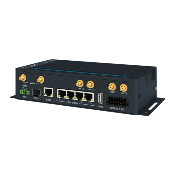
ICR-4461 1.3 Hardware Overview The router case preview is shown in Figure 5. A short description of hardware parts of the router is listed in Table 1, including the links to the chapters with a detailed description. Figure 5: Hardware Overview of the Router... -
Page 12: Hardware Overview Of The Router
ICR-4461 Item/Caption Type Description LEDs — Status LED indication; see Chapter 2.12. — Button to reboot the router or to restore the default configuration; see Chapter 2.13. 2-pin Power supply socket; see Chapter 2.6. terminal ETH2 SFP cage SFP cage socket for modules with speed up to 10 Gbps;... -
Page 13: Order Codes
ICR-4461 1.4 Order Codes Order codes overview is shown in the table below. Order code Configuration ICR-4461 5G NR cellular module, Gb ETH SWITCH, GNSS, SFP cage, USB, microSD card slot, RS232, RS485, CAN bus, two binary inputs, two binary outputs,... -
Page 14: Package Contents
ICR-4461 1.5 Package Contents The standard set of router includes items listed in the following table: Item# Description Figure Q’ty Router 1 pcs Wing for wall mounting 2 pcs (screwed on the router) 2-pin terminal block for power supply 1 pcs... -
Page 15: Product Dimensions
ICR-4461 1.6 Product Dimensions For the dimensions of the router see the figures below. Note that all sizes are measured in millimeters. Variant with Wall Mounting Clip Figure 6: Router Dimensions – Front, Top and Right view with Wall Mounting holder... -
Page 16: Router Dimensions - Front, Top And Right View With Din Holder
ICR-4461 Variant with DIN Rail Clip Figure 7: Router Dimensions – Front, Top and Right view with DIN holder... -
Page 17: Mounting Recommendations
ICR-4461 1.7 Mounting Recommendations The router can be placed: • on a flat surface, • on a wall using the wall mounting clip (see Chapter 1.8), • on a DIN rail EN 60715 with the metal DIN rail clip (see Chapter 1.9) -
Page 18: Wall Mounting
ICR-4461 1.8 Wall Mounting The wall mounting clip is supplied with the router as standard accessories. The router can be screwed to a wall (or another surface) using the wall mounting clips. Two wall mounting clips are assembled to the router during the production and need to be roteted as shown of Figure 8. -
Page 19: Din Rail Mounting
ICR-4461 1.9 DIN Rail Mounting The DIN rail clips are not supplied with the router as standard accessories, but they can be ordered by the order code BB-DIN-ICR32 (two pieces for one router). Two DIN rail clips can be assembled to the router and used to mount it to the DIN rail which meets the 60715 standards. -
Page 20: Product Label
ICR-4461 1.10 Product Label The figure below shows an example of the product labels with all the information printed on them. Figure 11: Product Label... -
Page 21: Hardware Functionality
ICR-4461 2. Hardware Functionality See Chapter for the product hardware overwiew. Table lists a short description of the hardware, including the links to the chapters with a detailed description. 2.1 SIM Card Slots Slots for two SIM cards are located on the router under a metal cover. If you intend to use this device to communicate over a cellular network, please place an activated data-provisioned SIM card into the SIM card reader. -
Page 22: Antennas Interfaces
ICR-4461 2.2 Antennas Interfaces SMA female connectors ANT and DIV are intended to be used for connection of the cellular antennas to the router. The GNSS antenna’s SMA female connectors are shared with the cellular connectors and can be connected to the ANT3 for the L1 band and to the ANT1 for the L5 band. -
Page 23: Power Over Ethernet (Poe) Pse
ICR-4461 2.4 Power over Ethernet (PoE) PSE Available only for models with PoE PSE feature; see Chapter for the order codes. The IEEE 802.3af/PoE (Type 1) and IEEE 802.3at/PoE+ (Type 2) standards are supported. The device is Mode B compliant. -
Page 24: Poe Pse Parameters
Table 5: PoE PSE Parameters PoE Power Budget Examples Example #1 This example is for the Advantech RPS-ICR4-WR2-PSE power supply, which can supply a power of 65 W. We will use 15 W as the maximum router power consumption; see Chap- ter 4.1. -
Page 25: Sfp Cage
ICR-4461 2.5 SFP Cage A hot-pluggable (SFP) network interface module with a speed of up to 10 Gbps can be settled into the ETH2 SFP cage. Installing an SFP Module To install a SFP module, see Figure and follow these steps: •... -
Page 26: Power Supply
ICR-4461 2.6 Power Supply Two pin terminal connector with 3.5 mm pitch is used to power the router. Corresponding connector is supplied with the router as a standard accessories. Signal mark Description VCC(+) Positive pole of DC supply voltage (+9 to +48 V DC) -
Page 27: Low Power Mode
ICR-4461 All metal parts, including the box, are connected together with the negative pole of the power supply (common pole). If recommended for the installation environment, protect the router by grounding it properly by the grounding screw, see Figure 17. -
Page 28: I/O Port Interfaces
ICR-4461 2.8 I/O Port Interfaces The I/O user interface is designed for binary input processing and binary output control. The pinout of the I/O interface is described in Figure and Table 8. For detailed electrical parameters see Chapter 4.7. The functional scheme of connection for the binary input and binary output is in Figure 19. -
Page 29: Serial Interfaces
ICR-4461 2.9 Serial Interfaces The RS232, RS485 CAN serial interfaces together with the two I/O interfaces are physically connected to the 14-pin terminal block panel socket. All these interfaces are not isolated from the router. The pinout of this connector is described in Figure and the tables below. -
Page 30: Usb Port
ICR-4461 2.10 USB Port There is one USB 2.0 host port with socket of USB-A type. USB Mass Storages and FTDI serial converters are supported. For a piece of advice, how to fix an unsupported FTDI chip, see the Commands and Scripts application note, chapter How to Use Unsupported FTDI Chip. -
Page 31: Microsd Card Reader
ICR-4461 2.11 MicroSD Card Reader The microSD card reader is located on the router’s rear panel under a metal cover. This card reader allows the router to operate with microSD memory cards. The technical speci- fications are stated in the table below. The microSD card changing procedure is described below. - Page 32 ICR-4461 Mounting microSD Card to the System It is necessary to mount the microSD card to be able to access it in the system of the router. Follow these steps to mount the card: • Use the dmesg command to see the list of recently connected devices.
-
Page 33: Led Status Indication
ICR-4461 2.12 LED Status Indication There are status LEDs on the top side of the router to provide router status information. Moreover, ETH0 and ETH1 connectors, located on the front panel, have two additional LEDs providing information about the port status. -
Page 34: Reset Functions
ICR-4461 2.13 Reset Functions Consider creating a router configuration backup before performing the router’s factory reset. The RST button can be used in three different scenarios: • Reset: Hold the RST button for less than 4 seconds; the router will reboot, applying its customized configuration. -
Page 35: First Use
ICR-4461 3. First Use 3.1 Accessories Connection Before putting the router into operation, it is necessary to connect all the components required to run your applications; see Chapter for the hardware overview. Remember to insert a SIM card for the cellular connection; see Chapter 2.1. -
Page 36: Router's Web Interface
ICR-4461 Figure 24: Router’s Web Interface A detailed description of the router settings in the web interface can be found in the configura- tion manual of the router. -
Page 37: Technical Parameters
ICR-4461 4. Technical Parameters 4.1 Basic Parameters Parameter Description Temperature range Operating -40 C to +75 C (-40 F to +167 F) Storage -40 C to +85 C (-40 F to +185 F) Humidity Operating 5 to 95 % relative humidity non condensing... -
Page 38: Standards And Regulations
ICR-4461 4.2 Standards and Regulations Parameter Description Radio EN 301 908-1, EN 301 908-2, EN 301 908-13, EN 301 908-25, EN 303 413, EN 301 893, EN 300 328, FCC part 22H, FCC part 24E, FCC part 27, FCC part 90R, PTCRB ETSI EN 301 489-1, ETSI EN 301 489-17, ETSI EN 301 489-19, ETSI EN 301 489-52, FCC Part 15.B, IEC 61000-6-2, IEC 61000-... -
Page 39: Type Tests And Environmental Conditions
ICR-4461 4.3 Type Tests and Environmental Conditions Phenomena Test Description Test levels EN 61000-4-2 Enclosure contact 6 kV (crit. A) RF field AM EN 61000-4-3 Enclosure 20 V/m (crit. A) modulated (80 – 1000 MHz) 10 V/m (crit. A) (1 – 6 GHz) -
Page 40: Parameters Of Cellular Module
ICR-4461 4.4 Parameters of Cellular Module Parameter Description • Connector type: SMA (4 pcs) Antenna • Input impedance: 50 • VSWR: • Efficiency: > 30 % • 3GPP Relelase 16 5G NR parameters • Supported modulations: /2-BPSK, QPSK, 16QAM, 64QAM and 256QAM for uplink;... -
Page 41: Technical Parameters Of Cellular Module
ICR-4461 Continued from previous page Parameter Description • 3GPP Relelase 16 (DL Cat 19 / UL Cat 18) LTE parameters • Supported modulations: QPSK, 16QAM, 64QAM and 256QAM (uplink/downlink) • 4 x 4 MIMO downlink for B1, B2, B3, B4, B7, B25, B30, B38, B40, B41, B42, B43, B48, B66 •... -
Page 42: Module Antenna Mapping
ICR-4461 4.4.1 Module Antenna Mapping Description ANT0 Antenna 0 interface: 5G NR: • Refarmed: LB_TX0/PRX & MHB_TX0/PRX & UHB_TX1/DRX • n41_TX0/PRX • n77/n78/n79_TX1/DRX LTE: LB_TX0/PRX & MHB_TX0/PRX & UHB_TX1/DRX WCDMA: LMB_TRX ANT1 Antenna 1 interface: 5G NR: • Refarmed: MHB_PRX MIMO & UHB_PRX MIMO •... -
Page 43: Parameters Of Gnss
ICR-4461 4.5 Parameters of GNSS Parameter Description GNSS Systems GPS, GLONASS, BDS, Galileo, QZSS Antenna Connector type: SMA Input impedance: 50 Antenna connection: • shared with cellular SMA connectors • ANT3 for L1 band • ANT1 for L5 band Frequency range: •... -
Page 44: Parameters Of Wifi
ICR-4461 4.6 Parameters of WiFi Parameter Description Short Module Description 802.11ac/a/b/g/n Dual-Band 2T2R Supported Standards IEEE 802.11ac/a/b/g/n (2T2R) Antenna Connectors 2x2 MIMO RP-SMA Input impedance: 50 Data Rate 802.11b: 11 Mbps 802.11a/g: 54 Mbps 802.11n: up to 300 Mbps (MCS0˜15) 802.11ac: up to 867 Mbps (MCS0˜9) -
Page 45: Parameters Of I/O Ports
ICR-4461 4.7 Parameters of I/O Ports Electrical characteristics of the binary input are in Table 22. Status of the binary input can be retrieved in the router’s web interface (on the General Status page) or by the status ports and io get commands, see Commands and Scripts application note. -
Page 46: Parameters Of Poe
ICR-4461 4.9 Parameters of PoE For more information about the PoE PSE feature, including the parameters, see Chapter 2.4. 4.10 System Configuration The main parametes of the system are listed in Table 24. Parameter Description CPU architecture Quad-Core ARMv8-A (core Cortex-A72) -
Page 47: Appendix A: Troubleshooting
ICR-4461 Appendix A: Troubleshooting If you cannot connect to the router from your PC, your network card may be configured in such a way that it is not possible to connect to the router. Take one or more of the following steps in order to solve the problem: •... - Page 48 ICR-4461 I can’t access my Web server placed behind the router over NAT. • The remote HTTP access to the router has to be disabled on "NAT Configuration" page in the router. Also enable "Send all remaining incoming packets to default server"...
- Page 49 ICR-4461 Serial communication is not working. • Verify that the router model supports serial communications. Also verify the serial communication settings. To do so, open the router’s configuration menu via the web browser, select the appropriate "Expansion Port" from "Configuration" part of the menu and verify the settings.
-
Page 50: Appendix B: Customer Support
ICR-4461 Appendix B: Customer Support Customer Support for Europe Advantech Czech s.r.o. Sokolska 71 562 04, Usti nad Orlici Czech Republic Phone: +353 91 792444 Fax: +353 91 792445 E-mail: [email protected] Web: www.advantech.com Customer Support for NAM Advantech B+B SmartWorx... -
Page 51: Appendix C: Regulatory & Safety Information
ICR-4461 Appendix C: Regulatory & Safety Information Safety Notices Please, observe the following instructions: • The router must be used in compliance with all applicable international and national laws and in compliance with any special restrictions regulating the utilization of the router in prescribed applications and environments. - Page 52 ICR-4461 Product Disposal Instructions The WEEE (Waste Electrical and Electronic Equipment: 2012/19/EU) directive was in- troduced to ensure that electrical/electronic products are recycled using the best available recovery techniques to minimize the environmental impact. This product contains high quality materials and components which can be recycled. At the end of it’s life this pro- duct MUST NOT be mixed with other commercial waste for disposal.
-
Page 53: Appendix D: Related Documents
ICR-4461 Appendix D: Related Documents ICR-4400 Configuration Manual [EP] Product-related documents and applications can be obtained on Engineering Portal at https://icr.advantech.cz/download address. - Page 54 ICR-4461 We, Advantech Czech s.r.o., declare that the radio equipment narrated in this user’s manual complies with Directive 2014/53/EU. We, Advantech Czech s.r.o., declare that the radio equipment narrated in this user’s manual complies with Radio Equipment Regulations 2017 (S.I. 2017 No. 1206).