
Related Manuals for Fujitsu PRIMERGY CX2550 M2


Summary of Contents for Fujitsu PRIMERGY CX2550 M2
- Page 1 Upgrade and Maintenance Manual - English FUJITSU Server PRIMERGY CX2550 M2 Server Node Upgrade and Maintenance Manual Edition March 2016...
- Page 2 – The contents of this manual may be revised without prior notice. – Fujitsu assumes no liability for damages to third party copyrights or other rights arising from the use of any information in this manual. – No part of this manual may be reproduced in any form without the prior written permission of Fujitsu.
- Page 3 Before reading this manual For your safety This manual contains important information for safely and correctly using this product. Carefully read the manual before using this product. Pay particular attention to the accompanying manual "Safety Notes and Regulations" and ensure these safety notes are understood before using the product.
- Page 4 Please consult the sales staff of Fujitsu if intending to use this product for high safety use. Measures against momentary voltage drop This product may be affected by a momentary voltage drop in the power supply caused by lightning.
- Page 5 Only for the Japanese market: Although described in this manual, some sections do not apply to the Japanese market. These options and routines include: – CSS (Customer Self Service) – USB Flash Module (UFM) Upgrade and Maintenance Manual CX2550 M2...
- Page 6 Version history Issue number Reason for update 1.0 / March 2016 Initial release Upgrade and Maintenance Manual CX2550 M2...
-
Page 7: Table Of Contents
Contents Introduction ......15 Notational conventions ....16 Before you start . - Page 8 Contents Removing a controller from the riser module ..47 Removing the memory slot air ducts ....48 Installing the memory slot air ducts ....49 4.9.1 Design of the memory air ducts .
- Page 9 Contents 5.2.14 Looking up changed MAC / WWN addresses ..80 5.2.14.1 Looking up MAC addresses ....80 5.2.14.2 Looking up WWN addresses .
- Page 10 Contents 6.4.1 Replacing the riser card ..... 114 6.4.1.1 Preliminary steps ..... . 114 6.4.1.2 Replacing the riser card .
- Page 11 Contents 8.2.6.3 Installing the heat sinks ....143 8.2.7 Concluding steps ......144 Replacing the processor heat sink .
- Page 12 Contents 9.3.2.3 Concluding steps ..... . 171 9.3.3 Replacing the UFM board ....171 9.3.3.1 Preliminary steps .
- Page 13 Contents 10.1.2.4 Concluding steps ..... . . 198 10.2 Cooling pads on the memory modules ... . 199 10.2.1 Basic information .
- Page 14 Contents Upgrade and Maintenance Manual CX2550 M2...
-
Page 15: Introduction
Introduction This Upgrade and Maintenance Manual provides instructions for the following procedures: Upgrading the server configuration by adding optional hardware ● components Upgrading the server configuration by replacing existing hardware ● components with superior ones. Replacing defective hardware components ● This manual focuses on on-site maintenance tasks. -
Page 16: Notational Conventions
Introduction Notational conventions The following notational conventions are used in this manual: indicates commands or menu items Text in italics indicates system output fixed font indicates text to be entered by the user semi-bold fixed font "Quotation marks" indicate names of chapters and terms that are being emphasized describes activities that must be performed in the order Ê... -
Page 17: Before You Start
The operating manual of your server node gives an introduction to server node features and provides an overview of available hardware options. Use the Fujitsu ServerView Suite management software and the iRMC web frontend to prepare hardware expansions. ServerView Suite documentation is available online at http://manuals.ts.fujitsu.com... - Page 18 Japanese market: http://jp.fujitsu.com/platform/server/primergy/system/ Please contact your local Fujitsu customer service partner for details on how to order expansion kits or spare parts. Use the Fujitsu Illustrated Spares Catalog to identify the required spare part and obtain technical data and order information.
-
Page 19: Classification Of Procedures
At the beginning of each procedure, the involved unit type is indicated by one of the symbols introduced in this section. Please ask your local Fujitsu service center for more detailed information. 2.1.1 Customer Replaceable Units (CRU) -
Page 20: Upgrade And Repair Units (Uru)
Before you start 2.1.2 Upgrade and Repair Units (URU) Upgrade and Repair Units (URU) Upgrade and Repair Units are non hot-plug components that can be ordered separately to be installed as options (Upgrade Units) or are available to the customer through customer self service (Repair Units). Server management error messages and diagnostic indicators on the front panel and system board will report defective Upgrade and Repair Units as customer replaceable CSS components. -
Page 21: Field Replaceable Units (Fru)
Maintenance procedures involving Field Replaceable Units must be performed exclusively by Fujitsu service personnel or technicians trained by Fujitsu. Please note that unauthorized interference with the system will void the warranty and exempt the manufacturer from all liability. Components that are handled as Field Replaceable Units –... -
Page 22: Average Task Duration
Before you start Average task duration Average task duration: 10 minutes The average task duration including preliminary and concluding steps is indicated at the beginning of each procedure next to the procedure class. Refer to table 1 on page 22 for an overview of steps taken into account for calculating the average task duration: Step... -
Page 23: Tools You Need At Hand
Before you start Tools you need at hand When preparing the maintenance task, ensure that all required tools are available according to the overview below. You will find a list of required tools at the beginning of each procedure. Screw driver / Screw Usage Type... -
Page 24: Documents You Need At Hand
– Ensure to store all printed manuals enclosed with your server in a save place for future reference. – Unless stated otherwise, all manuals are available online at http://manuals.ts.fujitsu.com under x86 servers. For the Japanese market please use the following address: http://jp.fujitsu.com/platform/server/primergy/manual/... -
Page 25: Documents For The Server Node
"Safety notes and regulations" manual Important safety information, available online or as a printed copy " 安全上のご注意 " for the Japanese market "FUJITSU Server PRIMERGY CX2550 M2 Server Node" Available online Operating Manual "D3343 BIOS Setup Utility for Information on configurable BIOS options... -
Page 26: Documents For The Server Enclosure
Table 3: Documentation you need at hand for the server node 2.4.2 Documents for the server enclosure Document Description "Quick Start Hardware - FUJITSU Server PRIMERGY Available online CX400 M1" leaflet "FUJITSU Server PRIMERGY CX400 M1 Server Enclosure" Available online... -
Page 27: Important Information
Important information CAUTION! Before installing and starting up a device, please observe the safety instructions listed in the following section. This will help you to avoid making serious errors that could impair your health, damage the device and endanger the data base. Safety instructions The following safety instructions are also provided in the manual "Safety Notes and Regulations"... - Page 28 Important information Before starting up During installation and before operating the device, observe the instructions ● on environmental conditions for your device. If the device is brought in from a cold environment, condensation may form ● both inside and on the outside of the device. Wait until the device has acclimatized to room temperature and is absolutely dry before starting it up.
- Page 29 Important information Always connect the server and the attached peripherals to the same power ● circuit. Otherwise you run the risk of losing data if, for example, the server is still running but a peripheral device (e.g. memory subsystem) fails during a power outage.
- Page 30 Important information Only set screen resolutions and refresh rates that are specified in the ● operating manual for the monitor. Otherwise, you may damage your monitor. If you are in any doubt, contact your sales outlet or customer service center. Before installing/removing internal options to/from the server, turn off the ●...
- Page 31 Important information All batteries containing pollutants are marked with a symbol (a crossed-out ● garbage can). In addition, the marking is provided with the chemical symbol of the heavy metal decisive for the classification as a pollutant: Cd Cadmium Hg Mercury Pb Lead Working with optical disk drives and media When working with optical disk drives, these instructions must be followed.
- Page 32 Important information As a precaution, remove disks from the optical disk drive when the ● drive is not to be used for a long time. Keep the optical disk tray closed to prevent foreign matter, such as dust, from entering the optical disk drive.
- Page 33 Important information CAUTION! The optical disk drive contains a light-emitting diode (LED), which under certain circumstances produces a laser beam stronger than laser class 1. Looking directly at this beam is dangerous. Never remove parts of the optical disk drive casing! Modules with Electrostatic-Sensitive Devices Modules with electrostatic-sensitive devices are identified by the following sticker:...
- Page 34 Important information For a detailed description of how to handle ESD components, see the relevant European or international standards (EN 61340-5-1, ANSI/ESD S20.20). Transporting the server Only transport the server in its original packaging or in packaging that ● protects it from impacts and jolts. For the Japanese market, transporting the device in its original packaging does not apply.
-
Page 35: Ce Conformity
Important information Notes on installing the server in the rack For safety reasons, at least two people are required to install the server ● in the rack because of its weight and size. (For the Japanese market, please refer to " 安全上のご注意 ".) Never lift the server into the rack using the handles on the front panel. -
Page 36: Fcc Class A Compliance Statement
Consult the dealer or an experienced radio/TV technician for help. ● Fujitsu is not responsible for any radio or television interference caused by unauthorized modifications of this equipment or the substitution or attachment of connecting cables and equipment other than those specified by Fujitsu. The correction of interferences caused by such unauthorized modification, substitution or attachment will be the responsibility of the user. -
Page 37: Environmental Protection
Important information Environmental protection Environmentally-friendly product design and development This product has been designed in accordance with the Fujitsu standard for "environmentally friendly product design and development". This means that key factors such as durability, selection and labeling of materials, emissions, packaging, ease of dismantling and recycling have been taken into account. - Page 38 Details regarding the return and recycling of devices and consumables within Europe can also be found in the "Returning used devices" manual, via your local Fujitsu branch or from our recycling center in Paderborn: Fujitsu Technology Solutions Recycling Center D-33106 Paderborn Tel.
-
Page 39: Basic Hardware Procedures
Basic hardware procedures Shutting down the server node Safety notes CAUTION! For further safety information, please refer to chapter "Important information" on page This step is only required when upgrading or replacing non-hot plug components. Ê Inform the system administrator that the server node will be shut down and put offline. -
Page 40: Removing The Server Node From The Server Enclosure
Basic hardware procedures Removing the server node from the server enclosure CAUTION! Shut down the server node and disconnect all external cables. ● Follow the safety instructions in the chapter "Important information" ● on page The server node slot must not be left open for more than 60 minutes. ●... -
Page 41: Removing The Riser Module
Basic hardware procedures Removing the riser module Figure 3: Removing the riser module at the left side An expansion card can only be installed if the riser module has been removed. Ê Remove the riser module from the chassis by pulling the riser module out of the slot and the bolt out of the chassis sparing (see circle). - Page 42 Basic hardware procedures Figure 4: Riser module at the right side Ê Remove the riser module at the right side accordingly from the chassis by pulling the riser module out of the slot and the bolt out of the chassis sparing (see circle).
-
Page 43: Installing The Riser Module
Basic hardware procedures Installing the riser module Figure 5: Installing the riser module Ê Install the riser module to the chassis by inserting the bolt into the chassis sparing (see circle) and press down the riser module until the connector of the riser card fits within the slot. - Page 44 Basic hardware procedures Figure 6: Riser module at the right side Ê Install the riser module on the right side accordingly. Upgrade and Maintenance Manual CX2550 M2...
-
Page 45: Replacing The Riser Card
Basic hardware procedures Replacing the riser card Figure 7: Replacing the riser card The riser module consists of the riser metal bracket and the riser card. The riser card is connected to the riser metal bracket with two rivets: – Rivet (1). –... -
Page 46: Mounting A Controller To The Riser Module
Basic hardware procedures Mounting a controller to the riser module Figure 8: Mounting a controller to the riser module Ê Plug the controller on the riser card connector (1). Make sure that the metal pin of the controller bracket hooks into the recess of the riser bracket (see circle). -
Page 47: Removing A Controller From The Riser Module
Basic hardware procedures Removing a controller from the riser module Figure 9: Removing a controller from the riser module Ê Pull the controller out of the riser card connector (1). Make sure that the metal pin of the controller bracket does not get stucked with the recess of the riser bracket (see circle). -
Page 48: Removing The Memory Slot Air Ducts
Basic hardware procedures Removing the memory slot air ducts Figure 10: Removing the memory slot air ducts Ê Push the air ducts together (1) and pull them out (2). Upgrade and Maintenance Manual CX2550 M2... -
Page 49: Installing The Memory Slot Air Ducts
Basic hardware procedures Installing the memory slot air ducts Figure 11: Installing the memory slot air ducts Ê Press down on the air ducts (see1 and 2) until they snap into their location between the memory modules. The air ducts only snap easily into place if all memory modules are installed properly. -
Page 50: Installing The Server Node In The Server Enclosure
Basic hardware procedures 4.10 Installing the server node in the server enclosure CAUTION! Follow the safety instructions in the chapter "Important information" ● on page Figure 13: Installing the server node Ê Push the server node at the handle into the server enclosure until the locking mechanism snaps into place. -
Page 51: Controls And Indicators On The Server Node
2 Global error LED 4 CSS indicator The server nodes are controlled via related operating panel areas on the front side of the CX400 M1 server enclosure. See "FUJITSU Server PRIMERGY CX400 M1 Server Enclosure Operating Manual". 4.12 Concluding software tasks Ê... - Page 52 Basic hardware procedures Upgrade and Maintenance Manual CX2550 M2...
-
Page 53: Basic Software Procedures
Basic software procedures Starting the maintenance task 5.1.1 Suspending BitLocker functionality BitLocker Drive Encryption provides protection for operating system and data drives by encrypting the contents and requiring users to authenticate their credentials to access the information. In the scenario described here, BitLocker uses the compatible Trusted Platform Module (TPM) to detect if the computer's startup process has been modified from its original state. -
Page 54: Disabling Svom Boot Watchdog Functionality
For further information on how to suspend BitLocker drive encryption, please refer to the Microsoft TechNet library at http://technet.microsoft.com/library/cc731549.aspx. Fujitsu service partners will find additional information (also available in Japanese) on the Fujitsu Extranet web pages. 5.1.2 Disabling SVOM boot watchdog functionality The ServerView Operations Manager boot watchdog determines whether the server boots within a preset time frame. -
Page 55: Configuring Boot Watchdog Settings
Basic software procedures Ê Under Boot Watchdog, you can obtain detailed information about the current watchdog status, time out intervals and actions that are triggered if watchdog time outs are exceeded. For detailed information on BIOS settings, refer to the corresponding BIOS Setup Utility reference manual. - Page 56 Basic software procedures Configuring boot watchdog settings in the BIOS Ê Enter the BIOS. Ê Select the Server Mgmt menu. Ê Under Boot Watchdog set the Action setting to Continue. Ê Save your changes and exit the BIOS. For detailed information on how to access the BIOS and modify settings, refer to the corresponding BIOS Setup Utility reference manual.
-
Page 57: Configuring Lan Teaming
Using Update Manager Express Ê If performing an offline BIOS / firmware update, first of all prepare the ServerView Update DVD or USB stick: Ê Download the latest ServerView Update DVD image from Fujitsu: for the EMEA market ftp://ftp.ts.fujitsu.com/images/serverview for the Japanese market: http://jp.fujitsu.com/platform/server/primergy/products/note/svsdvd/dvd/... - Page 58 Basic software procedures Ê In order to create a bootable USB stick, please proceed as described in the "Local System Update for PRIMERGY Servers" user guide. Ê Before using the ServerView Update DVD or USB stick in an offline environment, properly shut down the server and disconnect all external I/O connections (like LAN, FC or SAS cables) from the system.
- Page 59 Basic software procedures Using PrimeCollect To start PrimeCollect, proceed as follows: Ê Before using PrimeCollect in an offline environment, properly shut down the server and disconnect all external I/O connections (like LAN, FC or SAS cables) from the system. Only keep mouse, keyboard, video cable and AC power cord connected.
-
Page 60: Switching On The Id Indicator
Basic software procedures 5.1.5 Switching on the ID indicator When working in a datacenter environment, switch on the ID indicator on the front and rear connector panels of the server for easy identification. For further information, refer to the "ServerView Suite Local Service Concept (LSC)"... -
Page 61: Completing The Maintenance Task
Updating or recovering the system board BIOS Flash BIOS update For the Japanese market, follow the instructions provided separately. For Fujitsu PRIMERGY Servers you have basically the choice to select between online flash and offline flash: Online flash update: Flash BIOS update is processed while operating system is running. The system is accessible via network, and Flash BIOS update might be controlled online by administrator. -
Page 62
Basic software procedures Ê Select your system via Select Product or look under Product Search by Serial- /Identnumber for your system. Ê Select your operating system. Ê Select Flash-BIOS. For Online Flash – Select Flash BIOS
(ASP for Windows/Linux) –... -
Page 63
Basic software procedures For Linux: Ê Call "sh
.scexe [options ..]" from a command line interface. Get more information about possible options by calling " .scexe -- help". BIOS updates always require a closing system reboot. Offline Flash: Flash BIOS Update with an USB stick You need an USB stick on which the BIOS update files will be stored. - Page 64 Basic software procedures Flash Memory Recovery Mode For the Japanese market, follow the instructions provided separately. Ê Prepare a bootable USB stick as described in section "Flash BIOS update" on page Ê Switch off the system and disconnect the power plug. Ê...
-
Page 65: Updating Or Recovering The Irmc
Basic software procedures 5.2.1.2 Updating or recovering the iRMC iRMC flash procedure For the Japanese market, follow the instructions provided separately. Ê Prepare a USB stick including the bootable iRMC firmware update image. Ê Connect the USB stick to the USB port. Ensure that only the USB device with the iRMC firmware is connected to the USB port. - Page 66 Ê Press the Power On / Off button. The system starts the POST process. In iRMC recovery mode, the “FUJITSU” logo does not show up. Ê The system will detect the USB stick.
-
Page 67: Verifying System Information Backup / Restore
Chassis ID EPROM has been restored to the system board: Chassis IDPROM: Restore successful After replacing the Chassis ID EPROM In case of the PRIMERGY CX2550 M2 server, the Chassis ID EPROM is integrated on the chassis interface board. Ê Check the SEL log files as described in section "Viewing and clearing the... -
Page 68: Enabling Option Rom Scan
"Local System Update for PRIMERGY Servers" user guide Using the flash tool The latest firmware files are available as ASPs (Autonomous Support Packages) for Windows or as DOS tools from the Fujitsu support web pages at: http://ts.fujitsu.com/support/ (EMEA market) http://jp.fujitsu.com/platform/server/primergy/downloads/ (Japanese market) Ê... - Page 69 Basic software procedures Ê From the Advanced menu select Option ROM Configuration. Ê Identify the desired PCI slot and set its Launch Slot # OpROM setting to Enabled. Ê Save your changes and exit the BIOS. Up to two Option ROMs can be activated in the system board BIOS at a time.
-
Page 70: Resetting The Boot Retry Counter
Basic software procedures 5.2.5 Resetting the boot retry counter The boot retry counter is decremented from its preset value every time the POST watchdog initiates a system reboot. When the value has reached ’0’, the system will shut down and power off. 5.2.5.1 Viewing the boot retry counter The current boot retry counter status is available in the BIOS:... - Page 71 Basic software procedures Resetting the boot retry counter using the ServerView Operations Manager Ê In the ServerView Operations Manager Administration view, select Server Configuration. Ê If more than one server is managed in SVOM, select the target server and click Next. Ê...
-
Page 72: Enabling Svom Boot Watchdog Functionality
Basic software procedures 5.2.6 Enabling SVOM boot watchdog functionality If ServerView Operations Manager boot watchdog functionality has been disabled for firmware upgrade purposes (see section 5.1.2 on page 54), it has to be re-enabled to complete the maintenance task. Timer settings can be configured in the BIOS or using the ServerView iRMC web frontend: Configuring boot watchdog settings in the BIOS Ê... -
Page 73: Enabling Replaced Components In The System Bios
Basic software procedures 5.2.7 Enabling replaced components in the system BIOS When a processor, an expansion card, or a memory module fails, the defective component will be set to Disabled or Failed in the system BIOS. The server will then reboot with only the intact hardware components remaining in the system configuration. -
Page 74: Verifying The Memory Mode
Basic software procedures 5.2.8 Verifying the memory mode If a memory module fails, the server will reboot and the defective module will be disabled. As a result, the current operation mode may no longer be available due to a lack of identical memory module pairs. In this case, the operation mode will automatically revert to Independent Channel Mode. -
Page 75: Verifying The System Time Settings
Basic software procedures 5.2.9 Verifying the system time settings This task only applies to Linux environments. After the system board has been replaced, the system time is set automatically. By default, the RTC (Real Time Clock) time standard is set as the local time. If a Linux OS is used and the hardware clock has been configured as UTC (Universal Time, Coordinated) in the operating system, the iRMC local time may not be mapped correctly. -
Page 76: Viewing And Clearing The System Event Log (Sel)
Basic software procedures 5.2.10 Viewing and clearing the System Event Log (SEL) 5.2.10.1 Viewing the SEL You can view the System Event Log (SEL) using the ServerView Operations Manager or the ServerView iRMC web frontend: Viewing the SEL in ServerView Operations Manager Ê... -
Page 77: Clearing The Sel
Basic software procedures Viewing the SEL using the iRMC web frontend Ê Enter the ServerView iRMC web frontend. Ê Select the Event Log and choose the Internal Event Log submenu. Ê Under Internal Event Log Content the SEL is being displayed. In order to filter the list, select the check boxes next to the desired event types and press Apply for the changes to take effect. - Page 78 Basic software procedures Procedures may differ depending on your Linux OS or the definition file on the client system. Use the following information as reference. Ask the system administrator to change the definition file. Ê After replacing a network controller or the system board, switch on and boot the server as described in section "Controls and indicators on the server node"...
-
Page 79: Resuming Bitlocker Functionality
For further information on how to resume BitLocker drive encryption, please refer to the Microsoft TechNet library at http://technet.microsoft.com/library/cc731549.aspx. Fujitsu service partners will find additional information (also available in Japanese) on the Fujitsu Extranet web pages. Upgrade and Maintenance Manual... -
Page 80: Performing A Raid Array Rebuild
Basic software procedures 5.2.13 Performing a RAID array rebuild After replacing a hard disk drive that has been combined into a RAID array, RAID rebuild will be performed completely unattended as a background process. Ê Ensure that the RAID array rebuild has started normally. Wait until the progress bar has reached at least one percent. -
Page 81: Looking Up Wwn Addresses
Basic software procedures Ê Under Network Inventory, you will find detailed information on each network controller in the managed PRIMERGY server, including its MAC address. This information is only available with the iRMC S4 or above. Only network controllers supporting the Command Line Protocol (CLP) will be displayed. -
Page 82: Using The Chassis Id Prom Tool
After replacing the system board, system information has to be entered using the Chassis ID Prom tool. The tool and further instructions are available to maintenance personnel from the Fujitsu Technology Solutions Extranet: https://partners.ts.fujitsu.com/com/service/ps/Servers/PRIMERGY/ Ê Select your PRIMERGY system from the main area of the page. -
Page 83: After Replacing / Upgrading Lan Controllers
Basic software procedures For more detailed information, refer to the "ServerView Operations Manager - Server Management" user guide. 5.2.16.1 After replacing / upgrading LAN controllers Please note when re-using a replaced LAN controller: Ê Confirm with the customer whether the LAN controller you have replaced has been used as part of a LAN teaming configuration. -
Page 84: Performing A Fan Test
Basic software procedures Using the iRMC web frontend Ê Enter the ServerView iRMC web frontend. Ê Under System Overview, click Identify LED Off to switch off the ID indicators. Using ServerView Operations Manager Ê In ServerView Operations Manager Single System View and press the Locate button in the title bar to switch off the ID indicator. - Page 85 Basic software procedures In the left-hand section of the window, the Configuration tab is being activated. Ê In the navigation area of the Configuration tab, select Other Settings. Ê Under Daily Fan Test, set the daily fan test time to a few minutes from the current time.
-
Page 86: Resetting The Error Status After Replacing Memory Modules Or Processors
Using ServerView Maintenance Tools (Windows only) Ê Launch the ServerView Maintenance Tools: – Windows Server 2008 R2 and below: Start > (All) Programs > Fujitsu > ServerView Suite > Agents > Maintenance Tools – Windows Server 2012 and above: Start > Apps > Fujitsu > Maintenance Tools Ê... -
Page 87: Processors
Using ServerView Maintenance Tools (Windows only) Ê Launch the ServerView Maintenance Tools: – Windows Server 2008 R2 and below: Start > (All) Programs > Fujitsu > ServerView Suite > Agents > Maintenance Tools – Windows Server 2012 and above: Start > Apps > Fujitsu > Maintenance Tools... - Page 88 Basic software procedures Ê Choose the CPU status tab. Ê Select the CPU which shows the pre-failure status. Ê Click on Reset Status. Ê Ensure that all pre-fail / fail status issues have been resolved in ServerView Operations Manager. Using the command line (Linux only) Proceed as follows to reset the error counter of a specific processor: Ê...
- Page 89 Basic software procedures Ê Ensure that all pre-fail / fail status issues have been resolved in ServerView Operations Manager. Upgrade and Maintenance Manual CX2550 M2...
- Page 90 Basic software procedures Upgrade and Maintenance Manual CX2550 M2...
-
Page 91: Expansion Cards
Expansion cards Safety notes CAUTION! Do not damage or modify internal cables or devices. Doing so may ● cause a device failure, fire, or electric shock. Devices and components inside the server node remain hot after ● shutdown. After shutting down the server, wait for hot components to cool down before installing or removing internal options. -
Page 92: Basic Information
Expansion cards Basic information The system board is equipped with two expansion slots: Figure 16: PCI slot overview Slot Pos. Type Mechanical Function connector 11-14 PCI Gen3 CPU2 CPU1 (connected to GPGPU1 or PCI Gen3 Photonics) PCI Gen3 CPU1 15-18 PCI Gen3 CPU2 (connected to GPGPU2) Upgrade and Maintenance Manual... - Page 93 Intel XeonPhi 7120P Intel Grid K1 NVIDIA Grid K2 NVIDIA PSAS CP400e PSAS CP400i Fujitsu PRAID CP400i (Lynx4) Fujitsu PRAID EP400i 1GB cache Fujitsu PRAID EP420i 2GB cache Fujitsu PLAN CP 2x1Gbit Cu Intel I350-T2 Intel PLAN CP 2x1Gbit Cu Intel I350-T4...
- Page 94 The list may be changed due to new controllers. For the latest information on supported expansion cards, refer your server’s hardware configurator available online at the following address: for the EMEA market: http://ts.fujitsu.com/products/standard_servers/index.htm for the Japanese market: http://jp.fujitsu.com/platform/server/primergy/system/ Upgrade and Maintenance Manual...
-
Page 95: Additional Tasks
Expansion cards Additional tasks This section provides additional expansion card related information on how to install slot brackets and SFP+ transceiver modules. For further instructions regarding controller settings, please refer to the accompanying documentation. 6.2.1 Mounting expansion card slot brackets Upgrade and Repair Unit Hardware: 5 minutes (URU) -
Page 96: Network Adapter D2755
Expansion cards 6.2.1.2 Network adapter D2755 Figure 17: Placing the slot bracket - D2755 Ê Place the controller on the mounting tabs on the slot bracket (1). Ê Carefully shift the slot bracket towards the controller until the plug shells engage with the cut-outs in the slot bracket connector panel (2). - Page 97 Expansion cards Figure 18: Fastening the slot bracket - D2755 Ê Fasten the slot bracket to the controller with two M3 x 4.5 mm screws. Figure 19: Assembled network adapter D2755 Upgrade and Maintenance Manual CX2550 M2...
-
Page 98: Handling Sfp+ Transceiver Modules
Expansion cards 6.2.2 Handling SFP+ transceiver modules 6.2.2.1 Installing SFP+ transceiver modules Upgrade and Repair Unit Hardware: 5 minutes (URU) Tools: tool-less Preparing the SFP+ transceiver module Figure 20: Removing the protective optical port plug Ê Remove the SFP+ transceiver module from its protective packaging. Ê... - Page 99 Expansion cards Figure 21: Unlatching the locking bail Ê Carefully unlatch and fold down the locking bail on the SFP+ transceiver module. Upgrade and Maintenance Manual CX2550 M2...
- Page 100 Expansion cards Inserting the SFP+ transceiver module Figure 22: Inserting the SFP+ transceiver module Ê Insert and slide the SFP+ transceiver module into the socket connector as far as it will go. If only one slot is equipped with a SFP+ transceiver module, use the primary right connector as shown.
- Page 101 Expansion cards Figure 23: Latching the locking bail Ê Carefully fold up and latch the locking bail. Figure 24: Attaching the protective optical port plug Ê If the SFP+ transceiver module is not immediately connected to an LC connector, attach the protective optical port plug to the transceiver optical bores.
- Page 102 Expansion cards Installing the secondary SFP+ transceiver module Figure 25: Installing the secondary SFP+ transceiver module Ê If applicable, install the secondary SFP+ transceiver module accordingly. Upgrade and Maintenance Manual CX2550 M2...
-
Page 103: Removing An Sfp+ Transceiver Module
Expansion cards 6.2.2.2 Removing an SFP+ transceiver module Upgrade and Repair Unit Hardware: 5 minutes (URU) Tools: tool-less Figure 26: Removing the protective optical port plug Ê If present, remove the protective optical port plug from the SFP+ transceiver module. CAUTION! Save the protective port plug for future use. - Page 104 Expansion cards Figure 27: Unlatching the locking bail Ê Carefully unlatch and fold down the locking bail on the SFP+ transceiver module to eject the transceiver from the socket connector. Upgrade and Maintenance Manual CX2550 M2...
- Page 105 Expansion cards Figure 28: Removing the SFP+ transceiver Ê Pull the SFP+ transceiver module out of its socket connector. Ê Reattach the protective optical port plug to the transceiver optical bores. Place the removed SFP+ transceiver module in an antistatic bag or other protective environment.
-
Page 106: Replacing Sfp+ Transceiver Modules
Expansion cards 6.2.2.3 Replacing SFP+ transceiver modules Upgrade and Repair Unit Hardware: 5 minutes (URU) Tools: tool-less Removing SFP+ transceiver modules Ê Remove the defective SFP+ transceiver module(s) as described in section "Removing an SFP+ transceiver module" on page 103. Installing SFP+ transceiver modules Ê... -
Page 107: Expansion Cards In The Riser Module
Expansion cards Expansion cards in the riser module Safety notes CAUTION! Do not damage or modify internal cables or devices. Doing so may ● cause a device failure, fire, or electric shock. Devices and components inside the server remain hot after ●... -
Page 108: Installing Expansion Cards
Expansion cards 6.3.1 Installing expansion cards Upgrade and Repair Unit Hardware: 5 minutes (URU) Tools: Phillips PH2 / (+) No. 2 screw driver 6.3.1.1 Preliminary steps Perform the following procedures: "Disabling SVOM boot watchdog functionality" on page 54 Ê Ê Locate the desired server node with the ID button. "Shutting down the server node"... -
Page 109: Mounting A Controller To The Riser Module
Expansion cards 6.3.1.2 Mounting a controller to the riser module Figure 29: Mounting a controller to the riser module Ê Plug the controller on the riser card connector (1). Ê If applicable, reinstall SFP+ transceiver modules on the new expansion card, as described in section "Installing SFP+ transceiver modules"... -
Page 110: Removing Expansion Cards
Expansion cards "Controls and indicators on the server node" on page 51 Ê "Updating RAID controller firmware" on page 67 (if applicable) Ê "After replacing / upgrading LAN controllers" on page 83 (if applicable) Ê 6.3.2 Removing expansion cards Upgrade and Repair Unit Hardware: 5 minutes (URU) Tools: Phillips PH2 / (+) No. -
Page 111: Removing A Controller From The Riser Module
Expansion cards 6.3.2.2 Removing a controller from the riser module Figure 30: Removing a controller from the riser module Ê If the slot bracket on the defective expansion card is to be reused, remove it from the board as described in section "Mounting expansion card slot brackets"... -
Page 112: Replacing Expansion Cards
Expansion cards "Controls and indicators on the server node" on page 51 Ê 6.3.3 Replacing expansion cards Upgrade and Repair Unit Hardware: 5 minutes (URU) Tools: Phillips PH2 / (+) No. 2 screw driver Note on network settings recovery When replacing network controllers or the system board, network configuration settings in the operating system will be lost and replaced by default values. -
Page 113: Installing An Expansion Card
Expansion cards Ê If the slot bracket on the defective expansion card is to be reused, remove it from the board as described in section "Mounting expansion card slot brackets" on page 6.3.3.3 Installing an expansion card Ê If applicable, install a slot bracket on the new expansion card as described in section "Mounting expansion card slot brackets"... -
Page 114: Riser Card
Expansion cards Riser card CAUTION! Follow the safety instructions in chapter "Important information" on page 6.4.1 Replacing the riser card Upgrade and Repair Unit Hardware: 5 minutes (URU) Tools: – Phillips PH2 / (+) No. 2 screw driver – Phillips PH2 / (+) No. 2 screw driver) 6.4.1.1 Preliminary steps Perform the following procedures:... -
Page 115: Replacing The Riser Card
Expansion cards 6.4.1.2 Replacing the riser card Figure 31: Replacing the riser card The riser module consists of the riser metal bracket and the riser card. The riser card is connected to the riser metal bracket with two rivets: – Rivet (1). –... -
Page 116: Concluding Steps
Expansion cards 6.4.1.3 Concluding steps Perform the following procedures: Ê If applicable, re-install the expansion cards as described in section "Installing expansion cards" on page 108. "Installing the riser module" on page 43 Ê "Installing the server node in the server enclosure" on page 50 Ê... -
Page 117: Main Memory
Main memory Safety notes CAUTION! Do not install unsupported third party memory modules. For further ● information on supported memory modules, refer to section "Basic information" on page 118. Memory modules remain hot after shutdown. Wait for components to ● cool down before installing or removing memory modules to prevent burns. -
Page 118: Basic Information
Main memory Basic information – Each CPU offers 8 Slots for DDR4 memory modules organized in 2 banks and 4 channels. – Supported memory modules: There are 2 different kinds of DDR4 Memory Modules available: RDIMM and LRDIMM. – RDIMM / LRDIMM offer different functionality. Mix of RDIMM / LRDIMM is not allowed. - Page 119 Main memory Minimum configuration Minimum configuration is 2x CPU and 2x memory. Maximum configurations – 16x 64GB LRDIMM (quad rank modules) = 1024GB – 16x 16GB RDIMM (dual rank modules) = 256GB First Memory (one module) has to be selected for an orderable basic unit per CPU.
-
Page 120: Operation Modes
Main memory 7.1.2 Operation modes Independent Channel Mode CPU 1 CPU 2 Channel Color Slot descriptor No. of Modules 1 CPU populated 2 CPU populated Performance Channel Mode CPU 1 CPU 2 Channel Color Slot 1 CPU populated No. of Modules 2 CPU populated Upgrade and Maintenance Manual CX2550 M2... -
Page 121: Installing Memory Modules
Main memory Installing memory modules If liquid cooling is installed, first prepare the memory modules as described in section "Cooling pads on the memory modules" on page 199. Upgrade and Repair Unit Hardware: 5 minutes (URU) Tools: tool-less 7.2.1 Preliminary steps Perform the following procedures: "Disabling SVOM boot watchdog functionality"... -
Page 122: Installing A Memory Module
Main memory 7.2.2 Installing a memory module Figure 33: Installing memory modules (A) Ê Press out the securing clip at each end of the memory module connector. Figure 34: Installing memory modules (B) Ê Press down on the memory module until the securing clips snap into the cutouts at each end of the module. -
Page 123: Concluding Steps
Main memory 7.2.3 Concluding steps Perform the following procedures: "Installing the memory slot air ducts" on page 49 Ê Ê Connect the SATA cable(s) to the connectors on the system board described in section "Cabling for HDD 2.5"" on page 208 and reroute the cables as described in section "Cabling onboard"... -
Page 124: Removing Memory Modules
Main memory Removing memory modules Upgrade and Repair Unit Hardware: 5 minutes (URU) Tools: tool-less 7.3.1 Preliminary steps Perform the following procedures: "Disabling SVOM boot watchdog functionality" on page 54 Ê Ê Locate the desired server node. "Shutting down the server node" on page 39 Ê... -
Page 125: Removing A Memory Module
Main memory 7.3.2 Removing a memory module Figure 36: Removing memory modules (A) Ê Eject the desired memory module by pressing out the securing clips at each end of the memory module connector. Figure 37: Removing memory modules (B) Ê Remove the ejected memory module. Upgrade and Maintenance Manual CX2550 M2... -
Page 126: Concluding Step
Main memory 7.3.3 Concluding step Perform the following procedures: "Installing the memory slot air ducts" on page 49 Ê Ê Connect the SATA cable(s) to the connectors on the system board described in section "Cabling for HDD 2.5"" on page 208 and reroute the cables as described in section "Cabling onboard"... -
Page 127: Replacing Memory Modules
Main memory Replacing memory modules Upgrade and Repair Unit Hardware: 5 minutes (URU) Tools: tool-less 7.4.1 Preliminary steps Perform the following procedures: "Disabling SVOM boot watchdog functionality" on page 54 Ê Ê Locate the desired server node. "Shutting down the server node" on page 39 Ê... -
Page 128: Removing A Memory Module
Main memory 7.4.2 Removing a memory module Ê Identify the defective memory slot. Ê Remove the defective memory module as described in section "Removing memory modules" on page 124. 7.4.3 Installing a memory module Ê If applicable, prepare the new memory module as described in section "Preparing the memory modules"... -
Page 129: Processors
Processors Safety notes CAUTION! Do not install unsupported processors. For further information on ● supported processors, refer to section "Basic information" on page 130. Circuit boards and soldered parts of internal options are exposed and ● can be damaged by static electricity. Always discharge static build-up (e.g. -
Page 130: Basic Information
Processors Basic information 8.1.1 Supported processors – Intel Xeon E5-2600v4 processor series CPUs – Socket type: LGA 2011 package 8.1.2 Processor locations Figure 38: CPU slots on system board D3343 Upgrade and Maintenance Manual CX2550 M2... -
Page 131: Replacing Processors
Processors Replacing processors Field Replaceable Unit Hardware: 15 minutes (FRU) Software: 5 minutes Tools: – tool-less – Removing and installing the processor heat sink: – Phillips PH2 / (+) No. 2 screw driver – Removing and installing the processor: tool-less CAUTION! Processors are extremely sensitive to electrostatic discharge and must be handled with care. -
Page 132: Removing Processor Heat Sinks
Processors 8.2.2 Removing processor heat sinks If liquid cooling is installed, see section "Removing the liquid cooling kit" on page 189. 8.2.2.1 Removing the processor heat sinks Figure 39: Removing the processor heat sink Ê Carefully press on the middle of the heat sink and loosen the four captive screws in a crossover pattern according to the numbering. -
Page 133: Removing The Processor
Processors 8.2.3 Removing the processor Figure 40: Opening socket release lever 1 Ê Unlatch the socket release lever marked Open 1st by pushing it down and away from the socket (1). Ê The socket release lever will slightly lift up (2). Upgrade and Maintenance Manual CX2550 M2... - Page 134 Processors Figure 41: Opening socket release lever 2 Ê Unlatch the socket release lever marked Close 1st by pushing it down and away from the socket (1). Ê Fully fold back the second socket release lever (2). Upgrade and Maintenance Manual CX2550 M2...
- Page 135 Processors Figure 42: Opening the load plate (A) Ê Push down on the socket release lever marked Open 1st (1) to lift the load plate away from the socket (2). Upgrade and Maintenance Manual CX2550 M2...
- Page 136 Processors Figure 43: Opening the load plate (B) Ê Fully open the load plate. CAUTION! Be careful not to touch or bend the spring contacts on the processor socket. – If the processor may be reused later, thoroughly clean residual thermal paste from the processor surface using a lint-free cloth and store the processor in a save place.
-
Page 137: Installing The Processor
Processors 8.2.4 Installing the processor Figure 44: Installing the processor Ê Hold the processor with your thumb and index finger. Ê Make sure that the four notches on the processor align with the posts on the socket. Ê Lower the processor straight down without tilting or sliding it in the socket. CAUTION! –... - Page 138 Processors Figure 45: Installing the processor CAUTION! Always replace the socket cover if you remove the processor from the socket! Upgrade and Maintenance Manual CX2550 M2...
- Page 139 Processors Figure 46: Closing socket release lever 1 and 2 Ê Fully close and hold shut the load plate. Ê Close the socket release lever marked Close 1st (1) and latch it under the load plate retention tab to lock down the load plate (2). Upgrade and Maintenance Manual CX2550 M2...
-
Page 140: Applying Thermal Paste
Processors 8.2.5 Applying thermal paste For the Japanese market, the service engineer must follow the instruction provided separately. If the processor upgrade or replacement kit contains a new CPU heat sink, a thin layer of thermal compound has already been pre-applied to its lower surface. - Page 141 Processors Figure 48: Applying thermal paste Ê Apply a small streak of thermal paste (1.0 gram, see description above) to the center of the processor surface as shown. CAUTION! Do not mix different types of thermal paste. Upgrade and Maintenance Manual CX2550 M2...
-
Page 142: Installing The Processor Heat Sink
Processors 8.2.6 Installing the processor heat sink If liquid cooling is installed, see section "Installing a liquid cooling kit" on page 192. 8.2.6.1 Processor heat sink CPU1 Figure 49: Processor heat sink for CPU1 8.2.6.2 Processor heat sink CPU2 Figure 50: Processor heat sink for CPU2 Upgrade and Maintenance Manual CX2550 M2... -
Page 143: Installing The Heat Sinks
Processors 8.2.6.3 Installing the heat sinks Figure 51: Installing the processor heat sinks Ê Carefully seat the heat sink on the four threaded holes as shown. CAUTION! – Ensure that the screws on the heat sink are properly seated on the threaded holes (see circles). -
Page 144: Concluding Steps
Processors 8.2.7 Concluding steps Perform the following steps: "Installing the server node in the server enclosure" on page 50 Ê If the Global error LED is flashing with error message "CPU has been changed" on display after the system is powered on, please follow the procedure below. -
Page 145: Replacing The Processor Heat Sink
Processors Replacing the processor heat sink If liquid cooling is installed, see section "Replacing the liquid cooling kit" on page 189. Field Replaceable Unit Hardware: 15 minutes (FRU) Tools: – Preliminary and concluding steps: tool-less – Removing and installing the processor heat sink: –... -
Page 146: Concluding Steps
Processors 8.3.4 Concluding steps Perform the following steps: "Installing the server node in the server enclosure" on page 50 Ê If the Global LED is flashing with error message "CPU has been changed" on display after the system is powered on, please follow the procedure below. -
Page 147: System Board And Components
System board and components This chapter provides information on how to replace the system board module and system board components as its CMOS battery and the USB Flash Module (UFM). Safety notes CAUTION! Devices and components inside the server remain hot after ●... -
Page 148: Preliminary Steps
For further safety information, please refer to section "Environmental ● protection" in the PRIMERGY CX2550 M2 Operating Manual. Ensure to insert the CMOS battery with the positive pole facing ● 9.1.1... -
Page 149: Localization Of The Cmos Battery
System board and components 9.1.1.1 Localization of the CMOS battery Figure 52: System board battery Upgrade and Maintenance Manual CX2550 M2... -
Page 150: Removing The Cmos Battery
System board and components 9.1.2 Removing the CMOS battery Figure 53: Removing the CMOS battery Ê Pull out the depleted CMOS battery of its socket. Upgrade and Maintenance Manual CX2550 M2... -
Page 151: Installing The Cmos Battery
System board and components 9.1.3 Installing the CMOS battery Figure 54: Installing the CMOS battery Ê Insert the new CMOS battery into its socket as shown. CAUTION! Ensure to insert the CMOS battery with the positive pole (label side) facing to you as shown (see close-up). Upgrade and Maintenance Manual CX2550 M2... -
Page 152: Concluding Steps
System board and components 9.1.4 Concluding steps Perform the following procedures: Ê Dispose of the CMOS battery in accordance with local regulations concerning special waste. "Installing the riser module" on page 43 Ê "Installing the server node in the server enclosure" on page 50 Ê... -
Page 153: Sata Dom
System board and components SATA DOM The server node can be equipped with a SATA DOM. 9.2.1 Installing the SATA DOM board Upgrade and Repair Unit Hardware: 5 minutes (URU) Tools: Phillips PH1 / (+) No. 1 screw driver 9.2.1.1 Preliminary steps Perform the following procedures: "Disabling SVOM boot watchdog functionality"... -
Page 154: Installing The Sata Dom
System board and components 9.2.1.2 Installing the SATA DOM Figure 55: SATA DOM kit SATA DOM SATA DOM nylon spacer Upgrade and Maintenance Manual CX2550 M2... - Page 155 System board and components Figure 56: SATA DOM mounting location SATA DOM mounting location on the system board: SATA DOM connector SATA DOM spacer Upgrade and Maintenance Manual CX2550 M2...
- Page 156 System board and components Figure 57: Installing the SATA DOM spacer Ê Insert the spacer in the recess. The spacer must audibly click into place. Upgrade and Maintenance Manual CX2550 M2...
- Page 157 System board and components Figure 58: Installing the SATA DOM (A) Ê Connect the SATA DOM to the system board. Upgrade and Maintenance Manual CX2550 M2...
-
Page 158: Concluding Steps
System board and components Figure 59: Installing the SATA DOM (B) Ê The SATA DOM on the SATA DOM spacer must audibly click into place (see arrow). 9.2.1.3 Concluding steps Perform the following procedures: "Installing the riser module" on page 43 Ê... -
Page 159: Removing The Sata Dom
System board and components 9.2.2 Removing the SATA DOM Upgrade and Repair Unit Hardware: 5 minutes (URU) Tools: – Preliminary and concluding steps: tool-less – Main steps: – Phillips PH1 / (+) No. 1 screw driver 9.2.2.1 Preliminary steps Perform the following procedures: "Disabling SVOM boot watchdog functionality"... -
Page 160: Removing The Sata Dom
System board and components 9.2.2.2 Removing the SATA DOM Figure 60: Removing the SATA DOM board (A) Ê Disconnect and remove the SATA DOM spacer of the defective SATA DOM board. Ê Disconnect and remove the defective SATA DOM board. Upgrade and Maintenance Manual CX2550 M2... -
Page 161: Concluding Steps
System board and components Figure 61: SATA DOM spacer Ê The SATA DOM spacer remains on the system board (1). 9.2.2.3 Concluding steps Perform the following procedures: "Installing the riser module" on page 43 Ê "Installing the server node in the server enclosure" on page 50 Ê... -
Page 162: Replacing The Sata Dom
System board and components 9.2.3 Replacing the SATA DOM Upgrade and Repair Unit Hardware: 5 minutes (URU) Software: 10 minutes Tools: – Preliminary and concluding steps: – combination pliers and flat nose pliers – Main steps: – Phillips PH1 / (+) No. 1 screw driver 9.2.3.1 Preliminary steps Perform the following procedures:... -
Page 163: Re-Installing The Sata Dom
System board and components 9.2.3.3 Re-installing the SATA DOM Ê Secure the SATA DOM module on the SATA DOM spacer with the nylon screw as described in "Installing the SATA DOM" on page 154. 9.2.3.4 Concluding steps Perform the following procedures: "Installing the riser module"... -
Page 164: Usb Flash Module (Ufm)
System board and components USB Flash Module (UFM) The server node can be equipped with a USB Flash Module (UFM). 9.3.1 Installing the UFM board Upgrade and Repair Unit Hardware: 5 minutes (URU) Tools: – Preliminary and concluding steps: tool-less –... -
Page 165: Installing The Ufm Board
System board and components 9.3.1.3 Installing the UFM board Figure 62: UFM kit USB Flash Module (UFM) UFM nylon spacer Upgrade and Maintenance Manual CX2550 M2... - Page 166 System board and components Figure 63: UFM mounting location UFM mounting location on the system board: UFM connector UFM spacer Upgrade and Maintenance Manual CX2550 M2...
- Page 167 System board and components Figure 64: Installing the UFM spacer Ê Insert the plastic spacer in the recess next to the multi-pin connector for the TPM (see arrow). The plastic spacer must audibly click into place. Figure 65: Installing the UFM board (A) Ê...
-
Page 168: Concluding Steps
Ê 9.3.1.5 Software configuration In order to setup the ESXi configuration, the VMware ESXi Recovery Tools CD is required. An ISO image of the CD is available from the Fujitsu service partners portal at the following https address: https://globalpartners.ts.fujitsu.com/com/service/ps/Servers/PRIMERGY/ Pages/default.aspx. -
Page 169: Removing The Ufm Board
System board and components Ê Select the Software & Tools Documentation category. Ê Download the desired ESXi Recovery CD ISO image, listed under Tools. Ê Unpack and burn the image to a CD. Ê Ensure that no other USB storage device is connected to the server beside the UFM. -
Page 170: Removing The Ufm Board
System board and components 9.3.2.2 Removing the UFM board Figure 67: Removing the UFM board (A) Ê Disconnect and remove the nylon spacer of the defective UFM board (1). Ê Disconnect and remove the defective UFM board (2). Figure 68: UFM spacer Ê... -
Page 171: Concluding Steps
System board and components 9.3.2.3 Concluding steps Perform the following procedures: "Installing the riser module" on page 43 Ê "Installing the server node in the server enclosure" on page 50 Ê Ê If applicable, reconnect all external cables. "Controls and indicators on the server node" on page 51 Ê... -
Page 172: Re-Installing The Ufm
System board and components 9.3.3.3 Re-installing the UFM Ê Connect the UFM board to the system board and secure the UFM module on the UFM spacer with the nylon screw as described in "Installing the UFM board" on page 165. Destroying the defective UFM board CAUTION! The UFM board contains customer information (e.g. -
Page 173: Software Configuration
Ê 9.3.3.5 Software configuration In order to setup the ESXi configuration, the VMware ESXi Recovery Tools CD is required. An ISO image of the CD is available from the Fujitsu service partners portal at the following https address: https://globalpartners.ts.fujitsu.com/com/service/ps/Servers/PRIMERGY/ Pages/default.aspx. -
Page 174: Irmc Microsd Card
System board and components iRMC microSD card The iRMC microSD card is necessary for using the embedded Lifecycle Management (eLCM) functionality of the iRMC. It requires a valid eLCM license key, which is always purchased together with the iRMC microSD card and activated through the iRMC web frontend. -
Page 175: Installing The Irmc Microsd Card
System board and components 9.4.1.2 Installing the iRMC microSD card Figure 70: iRMC microSD card Figure 71: Installing the iRMC microSD card Ê With the label facing up, insert the iRMC microSD card into the microSD card slot (1) as far as it will go (2). The onboard position of the microSD card slot can be found in section "Connectors and indicators"... -
Page 176: Removing The Irmc Microsd Card
System board and components 9.4.2 Removing the iRMC microSD card Upgrade and Repair Unit Average task duration: (URU) 5 minutes Tools: tool-less 9.4.2.1 Preliminary steps "Disabling SVOM boot watchdog functionality" on page 54 Ê "Shutting down the server node" on page 39 Ê... -
Page 177: Concluding Steps
System board and components Destroying the defective iRMC microSD card CAUTION! The iRMC microSD card contains customer information. After replacing the iRMC microSD card, hand the defective card over to the customer. If the customer requests disposal of the defective iRMC microSD card, proceed as follows: Ê... -
Page 178: Replacing The Irmc Microsd Card
System board and components 9.4.3 Replacing the iRMC microSD card Upgrade and Repair Unit Average task duration: (URU) 5 minutes Tools: tool-less 9.4.3.1 Preliminary steps "Disabling SVOM boot watchdog functionality" on page 54 Ê "Shutting down the server node" on page 39 Ê... -
Page 179: Replacing The System Board
System board and components Replacing the system board Field Replaceable Unit Hardware: 50 minutes (FRU) Software: 10 minutes Tools: – tool-less – Removing and installing the processor heat sink: – Phillips PH2 / (+) No. 2 screw driver – Removing and installing the UFM (if applicable): –... -
Page 180: Preliminary Steps
System board and components 9.5.1 Preliminary steps Perform the following procedures: "Disabling SVOM boot watchdog functionality" on page 54 Ê Ê Locate the desired server with the ID button. "Shutting down the server node" on page 39 Ê Ê If applicable, remove all external cables from the server node. "Removing the server node from the server enclosure"... -
Page 181: Removing The System Board
System board and components 9.5.2.1 Removing the system board Figure 73: Removing the screw of the system board Ê Remove the screw from the system board (see circle). Upgrade and Maintenance Manual CX2550 M2... - Page 182 System board and components Figure 74: Removing the system board Ê Carefully shift the system board in the direction of the arrow until the plug shells disengage from the cut-outs in the connector panel (see circles). Ê Hold the defective system board by the memory module ejectors and at a slight angle lift it out of the chassis.
-
Page 183: Installing The System Board
System board and components 9.5.2.2 Installing the system board Figure 75: Installing the system board Ê Hold the new system board by the memory module ejectors. CAUTION! – Do not lift or handle the system board by any of its heat sinks! –... -
Page 184: Swapping Processors
System board and components Figure 76: Securing the screw of the system board Ê Secure the system board with the screw (see circle). 9.5.2.3 Swapping processors Preparing the processor socket load plates on the new system board "Installing the processor" on page 137 Ê... -
Page 185: Completing The System Board
System board and components Installing processors on the new system board "Installing the processor" on page 137. Ê Installing protective socket covers on the defective system board Since the defective system board is sent back for repair, protect the delicate processor socket springs with a socket cover. "Installing the processor"... - Page 186 System board and components "Updating or recovering the system board BIOS and iRMC" on page 61 Ê applicable) "Verifying the system time settings" on page 75 Ê Ê Inform the customer about changed WWN and MAC addresses. For further information, refer to section "Looking up changed MAC / WWN addresses"...
-
Page 187: Liquid Cooling
Memory Memory Slot 1-4 Slot 15-18 Figure 77: Main components of the PRIMERGY CX2550 M2 server node If liquid cooling is installed, slot 1-4 for modular RAID will not be supported. 10.1.1.2 Riser module for the liquid cooling kit Figure 78: Riser module for liquid cooling kit For installing the riser module see chapter "Installing the riser module"... -
Page 188: Liquid Cooling Kit
Liquid cooling 10.1.1.3 Liquid cooling kit Figure 79: PRIMERGY CX2550 M2 server node - liquid cooling kit Pos. Component Memory cover for DIMM channels C, D, E, F Memory cover for DIMM channel A, B, G, H Memory cooling tubes... -
Page 189: Replacing The Liquid Cooling Kit
Liquid cooling 10.1.2 Replacing the liquid cooling kit Field Replaceable Unit Hardware: 15 minutes (FRU) Software: 5 minutes Tools: Phillips PH2 / (+) No. 2 screw driver 10.1.2.1 Preliminary steps "Disabling SVOM boot watchdog functionality" on page 54 Ê "Shutting down the server node" on page 39 Ê... - Page 190 Liquid cooling Figure 81: Removing the memory covers Ê Remove both memory covers from the DIMM channels. CPU 2 CPU 1 Figure 82: Removing the pumps Ê First remove the four screws for CPU 1 in a crossover pattern (1, 2, 3, 4). Ê...
- Page 191 Liquid cooling Figure 83: Removing the riser module Ê Disconnect the power cable of the pump for CPU 2 from the connector (1) on the system board. Ê Disconnect the power cable of the pump for CPU 1 from the connector (2) on the system board.
-
Page 192: Installing A Liquid Cooling Kit
Liquid cooling Figure 84: Removing the flexible tubes (A) Ê Remove the three screws from the liquid cooling kit riser module. Figure 85: Removing the flexible tubes (B) Ê Pull the flexible tubes through the holes of the liquid cooling kit riser module. 10.1.2.3 Installing a liquid cooling kit If a new liquid cooling kit is used, a thin layer of thermal paste is applied to the lower surface. - Page 193 Liquid cooling Ê If using the liquid cooling kit removed before, see section "Applying thermal paste" on page 140. Figure 86: Removing the memory covers from the liquid cooling kit Ê If applicable, remove both memory covers from the liquid cooling kit. Keep the memory covers for future use.
- Page 194 Liquid cooling Figure 88: Installing the flexible tubes (A) Ê Push the flexible tubes through the holes of the liquid cooling kit riser module (see arrow). Figure 89: Installing the flexible tubes (B) Ê Fasten the screws of the bracket. Upgrade and Maintenance Manual CX2550 M2...
- Page 195 Liquid cooling Figure 90: Installing the riser module (A) Ê Insert the riser module with the liquid cooling kit at a slight angle (1). Ê Carefully place the pumps (2) of the liquid cooling kit on the eight threaded holes without fastening the screws. Ê...
- Page 196 Liquid cooling Figure 92: Installing the memory covers Ê Install both memory covers over the DIMM channels. Make sure not to damage anything when installing the memory covers (see arrow). Figure 93: Installing the riser module (B) Pos. Component Power connector for power cable of pump 2 Power connector for power cable of pump 1 Upgrade and Maintenance Manual CX2550 M2...
- Page 197 Liquid cooling Figure 94: Installing the riser module (C) Ê Press down the riser module (see arrow). – Make sure that the bolt snaps into the chassis sparing (see circle) and the connector of the riser card fits within the slot. –...
-
Page 198: Concluding Steps
Liquid cooling Figure 95: Power cable routing Ê Run the power cable of pump as shown. Figure 96: Installing the second riser module Ê Install the second riser module (1) as described in chapter "Installing the riser module" on page 10.1.2.4 Concluding steps Before powering on the server node connect the tubes to the tube system of the rack as described in the "RackCDU... -
Page 199: Cooling Pads On The Memory Modules
Liquid cooling Ê Restart the system and wait until the screen output appears. Ê Press the [F2] function key. Ê If a password is assigned, enter this password and confirm with the [Enter] key. The BIOS setup Main menu will be displayed on the screen. Ê... -
Page 200: Adhesive Rules For The Memory Cooling Pads
Liquid cooling 10.2.1.1 Adhesive rules for the memory cooling pads Memory modules 1A, 1C, 1E, 1G Figure 98: Memory modules 1A, 1C, 1E, 1G: joining face for the cooling pad The cooling pad must be stuck on the above shown side of the memory module. Memory modules 2B, 2D, 2H, 2F Figure 99: Memory modules 2B, 2D, 2H, 2F: joining face for the cooling pad The cooling pad must be stuck on the above shown side of the memory module. - Page 201 Liquid cooling Figure 100: Example: Memory modules with cooling pads built-in Memory Pos. Number of cooling pads module 1 cooling pad 2, 3 2 cooling pads 4, 5 2 cooling pads 1 cooling pad Upgrade and Maintenance Manual CX2550 M2...
-
Page 202: Preparing The Memory Modules
Liquid cooling 10.2.2 Preparing the memory modules Field Replaceable Unit Hardware: 15 minutes (FRU) Software: 5 minutes Tools: Phillips PH2 / (+) No. 2 screw driver 10.2.2.1 Preliminary steps "Disabling SVOM boot watchdog functionality" on page 54 Ê "Shutting down the server node" on page 39 Ê... - Page 203 Liquid cooling Ê Install the memory modules as described in section "Installing a memory module" on page 122 "Installing a liquid cooling kit" on page 192 Ê "Installing the server node in the server enclosure" on page 50 Ê If the Global LED is flashing with error message "CPU has been changed"...
- Page 204 Liquid cooling Upgrade and Maintenance Manual CX2550 M2...
-
Page 205: Cabling
Cabling This chapter provides information on how to connect, disconnect and route cables. Safety notes CAUTION! Always hold cables by their connectors when disconnecting them. ● Never pull on the cable to disconnect cables. Ensure that none of the cables are scraped, strained or otherwise ●... -
Page 206: Cabling Overview
Cabling 11.1 Cabling overview No. Part number (Label) Description Note T26139-Y4040-V13 Onboard SATA CBL PCH-BP T26139-Y4040-V12 RAID controller CBL CGR4-BP GPGPU (only for T26139-Y3946-V606 CBL GPU PWR CX2570 M1/2) GPGPU(K80) (only for T26139-Y3946-V609 CBL GPU PWR CX2570 M1/2) Table 5: List of used cables 11.2 Cabling Cabling onboard... - Page 207 Cabling Cabling with RAID controller RAID controller MLC1 D3343 RAID controller D3343 MoBo MLC2 MoBo SAS 0 - 3 SAS 0 - 3 SAS 4 - 5 SAS 4 - 5 GPGPU Riser Card GPGPU Riser Card GPGPU 1 GPGPU 2 Figure 103: Cabling with RAID controller Upgrade and Maintenance Manual CX2550 M2...
-
Page 208: Cabling For Hdd 2.5
Cabling 11.3 Cabling for HDD 2.5" 11.3.1 Cabling onboard Figure 104: Cabling onboard with cable T26139-Y4040-V13 Ê Plug one end of the SATA cable on the SAS connector (SAS 0-3) on the system board (1). Ê Plug the other end of the SATA cable on the SATA connector (SATA 0-3) on the system board (2). -
Page 209: Cabling With Raid-Controller
Cabling 11.3.2 Cabling with RAID-Controller Figure 106: Cabling with RAID controller with cable T26139-Y4040-V12 Ê Plug one end of the SATA cable on the SAS connector (SAS 0-3) on the system board (1). Ê Plug the other end of the SATA cable to the connector on the RAID controller (2). - Page 210 Cabling Upgrade and Maintenance Manual CX2550 M2...
-
Page 211: Appendix
Appendix 12.1 Mechanical overview 12.1.1 Server node interior Figure 108: Example: PRIMERGY CX2550 M2 server node interior (with heat sinks) Pos. Component USB Flash Module (UFM) SATA DOM (not visible, located under the riser module Riser module on the left side... -
Page 212: Server Node Rear
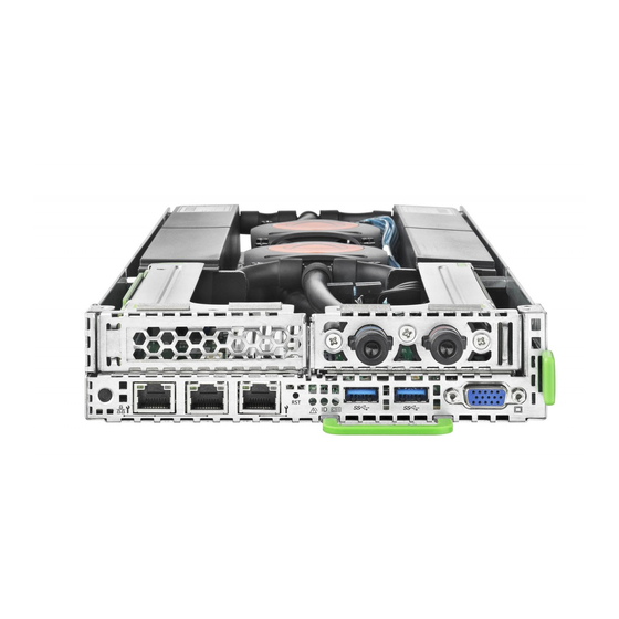
Appendix Pos. Component Network controller 12.1.2 Server node rear Figure 109: Connection panel of the server node 1 Shared LAN connector (LAN 1) 5 Video connector 2 Standard LAN connector (LAN 2) 6 PCI2 (connected to PCI slot 11-14 on system) 3 Management LAN connector 7 PCI1 (connected to PCI slot 1-4 on system) -
Page 213: Connectors And Indicators
Appendix 12.2 Connectors and indicators 12.2.1 Connectors and indicators on the system board 12.2.1.1 Onboard connectors Figure 110: Internal connectors of system board D3343 Upgrade and Maintenance Manual CX2550 M2... - Page 214 Appendix No. Print Description Reset button Power button CSS (orange) ID LED Identify (blue) Global Error LED (orange) LAN 1 LAN connector 1 LAN 2 LAN connector 2 LAN M Management LAN connector UFM connector PCI Slot 11-14 PCI Slot 11-14 (connected to PCI2) SATA DOM SATA Disk on module Jumper...
-
Page 215: Onboard Settings
Appendix 12.2.1.2 Onboard settings Figure 111: Jumper on system board Reset RTC Jumper position Function Default setting Reset RTC enabled Reset RTC disabled no jumper Table 6: Reset RTC Password Skip Jumper position Function Default setting PASSWORD CLEAR (SKIP) no jumper NORMAL MODE Table 7: Password skip Upgrade and Maintenance Manual... - Page 216 Appendix BIOS Recovery Jumper position Function Default setting BIOS Recovery enabled no jumper BIOS Recovery disabled Table 8: BIOS Recovery BIOS Write Protect Jumper position Function Default setting Flash Write Protect enabled 9-10 Flash Write Protect disabled no jumper Table 9: BIOS Write Protect Upgrade and Maintenance Manual CX2550 M2...
-
Page 217: Connector Panel
Global error indicator CSS indicator The server nodes are controlled via related operating panel areas on the front side of the CX400 M1 server enclosure. See "FUJITSU Server PRIMERGY CX400 M1 Server Enclosure Operating Manual". 12.2.2.2 Control elements Reset button Pressing the reset button reboots the system. -
Page 218: Global Error Indicator, Id Indicator, Css Indicator
Appendix 12.2.2.3 Global error indicator, ID indicator, CSS indicator Global error indicator (orange) – Lights up orange if a prefailure event has been detected that requires (precautionary) service intervention. – Flashes orange if an error was detected that requires service intervention. -
Page 219: Lan Indicators
Depending on the settings in the BIOS, the standard LAN connector 1 may also be used as a Management LAN connector. You will find further information in the "D3343 BIOS Setup Utility for FUJITSU Server PRIMERGY CX2550 M2 Reference Manual". -
Page 220: Minimum Startup Configuration
Appendix 12.3 Minimum startup configuration Field Replaceable Units (FRU) If the server does not start up or other problems occur, it may be necessary to take the system down to its most basic configuration in order to isolate the defective component. The minimum startup configuration consists of the following components and cables: Component... - Page 221 Appendix The minimum startup configuration must be used exclusively for diagnostic purposes by maintenance personnel, never in daily operation! Upgrade and Maintenance Manual CX2550 M2...
- Page 222 Appendix Upgrade and Maintenance Manual CX2550 M2...