Table of Contents
Quick Links
www.ti.com
User's Guide
ADS8353Q1EVM-PDK Evaluation Module
This user's guide describes the characteristics, operation, and use of the ADS8353-Q1 evaluation module
(EVM) performance demonstration kit (PDK). This kit is an evaluation platform for the ADS8353-Q1 device,
which is a 16-bit, dual-channel, simultaneous-sampling, 600-kSPS, single-ended and pseudo-differential analog
input, successive approximation register (SAR) analog-to-digital converter (ADC) that features an easy-to-use
serial programming interface (SPI). The ADS8353Q1EVM-PDK eases evaluation with hardware, software, and
computer connectivity through the universal serial bus (USB) interface. This user's guide includes complete
circuit descriptions, schematic diagrams, and a bill of materials (BOM).
The following related documents are available through the
SBAU327A – JANUARY 2019 – REVISED APRIL 2023
Submit Document Feedback
ABSTRACT
Table 1-1. Related Documentation
Device
ADS8353-Q1
OPA320-Q1
TPS7A47-Q1
REF34-Q1
Copyright © 2023 Texas Instruments Incorporated
Texas Instruments
website.
Literature Number
SBAS931
SLOS884
SBVS118
SBAS901A
ADS8353Q1EVM-PDK Evaluation Module
1
Table of Contents

Related Manuals for Texas Instruments ADS8353-Q1


Summary of Contents for Texas Instruments ADS8353-Q1
-
Page 1: Table 1-1. Related Documentation
This user's guide describes the characteristics, operation, and use of the ADS8353-Q1 evaluation module (EVM) performance demonstration kit (PDK). This kit is an evaluation platform for the ADS8353-Q1 device, which is a 16-bit, dual-channel, simultaneous-sampling, 600-kSPS, single-ended and pseudo-differential analog input, successive approximation register (SAR) analog-to-digital converter (ADC) that features an easy-to-use serial programming interface (SPI). -
Page 2: Table Of Contents
® ® Microsoft and Windows are registered trademarks of Microsoft Corporation. All trademarks are the property of their respective owners. ADS8353Q1EVM-PDK Evaluation Module SBAU327A – JANUARY 2019 – REVISED APRIL 2023 Submit Document Feedback Copyright © 2023 Texas Instruments Incorporated... -
Page 3: Overview
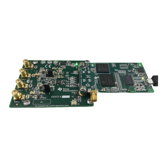
(PHI) controller board that enables the accompanying computer software to communicate with the ADC over the USB for data capture and analysis. The ADS8353-Q1EVM board includes the ADS8353-Q1 SAR ADC, all the peripheral analog circuits, and the components required to achieve optimum performance from the ADC. -
Page 4: Analog Interface
2 Analog Interface The ADS8353-Q1 is a low-power, dual-channel, simultaneous-sampling ADC that supports single-ended and pseudo-differential analog inputs. The ADS8353-Q1EVM uses an OPA320-Q1 to drive the analog inputs (AINP and AINM) of the ADC. The ADS8353-Q1EVM is designed for easy interfacing to analog sources. This section describes the front-end driver circuitry details, including jumper configurations for the analog input signal source. -
Page 5: Adc Input Signal Driver
ADC inputs dynamically low impedance. The analog inputs of the ADC are therefore driven by an OPA320-Q1 used in a unity-gain buffer configuration to maintain ADC performance with maximum loading at full device throughput of the ADS8353-Q1 of 600 kSPS. 2.2.1 Input Signal Path Figure 2-1 shows the signal path for the analog inputs applied to the ADS8353-Q1EVM. -
Page 6: Digital Interfaces
The PHI is capable of operating at a 3.3-V logic level and is directly connected to the digital I/O lines of the ADC. ADS8353Q1EVM-PDK Evaluation Module SBAU327A – JANUARY 2019 – REVISED APRIL 2023 Submit Document Feedback Copyright © 2023 Texas Instruments Incorporated... -
Page 7: Power Supplies
4 Power Supplies The ADS8353-Q1 supports a wide range of operation on the analog supplies. The AVDD operates from 4.5 V to 5.5 V. The DVDD operates from 1.65 V to 5.5 V, independent of the AVDD supply. The analog portion of the ADS8353-Q1EVM operates from a 5.3-V supply (VA) generated using the TPS7A47-Q1 low-noise, low-dropout... -
Page 8: Ads8353Q1Evm-Pdk Initial Setup
Use pin 1 of these jumpers as an alternate location to provide the analog input to ADC A and JP1, JP2, JP3, JP4 Open ADC B of the ADS8353-Q1. Open Connect this jumper to disable EEPROM write protection. Jumpers to feed either V or V / 2 to the OPA320-Q1 input driving the AINM pin of the ADC. -
Page 9: Evm Graphical User Interface Software Installation
2. Accept the license agreements (Figure 5-2) and follow the on-screen instructions to complete the installation. Figure 5-2. ADS835x EVM Software Installation Prompts SBAU327A – JANUARY 2019 – REVISED APRIL 2023 ADS8353Q1EVM-PDK Evaluation Module Submit Document Feedback Copyright © 2023 Texas Instruments Incorporated... -
Page 10: Figure 5-3. Device Driver Installation Wizard Prompts
A notice can appear on the screen stating that Windows cannot verify the publisher of this driver software. Select the Install this driver software anyway option. ADS8353Q1EVM-PDK Evaluation Module SBAU327A – JANUARY 2019 – REVISED APRIL 2023 Submit Document Feedback Copyright © 2023 Texas Instruments Incorporated... -
Page 11: Figure 5-4. Labview Run-Time Engine Installation
4. Check the Create Desktop Shortcut box, as Figure 5-5 shows, after these installations. Figure 5-5. ADS835x EVM Software Installation Final Step SBAU327A – JANUARY 2019 – REVISED APRIL 2023 ADS8353Q1EVM-PDK Evaluation Module Submit Document Feedback Copyright © 2023 Texas Instruments Incorporated... -
Page 12: Ads8353Q1Evm-Pdk Operation
3. Launch the device EVM GUI software from the installed path, as Figure 6-2 shows, or by using the desktop shortcut created during installation. Figure 6-2. Launch the EVM GUI Software ADS8353Q1EVM-PDK Evaluation Module SBAU327A – JANUARY 2019 – REVISED APRIL 2023 Submit Document Feedback Copyright © 2023 Texas Instruments Incorporated... -
Page 13: Evm Gui Global Settings For Adc Control
(or from one page to another). Figure 6-3. EVM GUI Global Input Parameters The ADS8353-Q1 interface configurations can be selected on this page. The GUI lets the user select the ADC input range, ADC input configuration (single-ended or pseudo-differential), ADC voltage reference, and ADC data format using a drop-down menu. -
Page 14: Time Domain Display Tool
Figure 6-4. Time Domain Display Tool Options ADS8353Q1EVM-PDK Evaluation Module SBAU327A – JANUARY 2019 – REVISED APRIL 2023 Submit Document Feedback Copyright © 2023 Texas Instruments Incorporated... -
Page 15: Spectral Analysis Tool
6-5) is intended to evaluate the dynamic performance (SNR, THD, SFDR, SINAD, and ENOB) of the ADS8353-Q1 SAR ADC through the use of a single-tone, sinusoidal signal FFT analysis, using the 7-term Blackman-Harris window setting. Alternatively, the window setting of None can be used to search for noise spurs over frequency in DC inputs. -
Page 16: Histogram Analysis Tool
ADC configured in single-ended, 0 V to 2 × V mode and with the AINP pin driven with the V input voltage. Figure 6-6. Histogram Analysis Tool ADS8353Q1EVM-PDK Evaluation Module SBAU327A – JANUARY 2019 – REVISED APRIL 2023 Submit Document Feedback Copyright © 2023 Texas Instruments Incorporated... -
Page 17: Bill Of Materials, Printed-Circuit Board Layout, And Schematics
RES, 10.0 k, 1%, 0.1 W, AEC-Q200 Grade 0, 0603 CRCW06035R11FKEA Vishay-Dale RES, 5.11, 1%, 0.1 W, AEC-Q200 Grade 0, 0603 SBAU327A – JANUARY 2019 – REVISED APRIL 2023 ADS8353Q1EVM-PDK Evaluation Module Submit Document Feedback Copyright © 2023 Texas Instruments Incorporated... - Page 18 Automotive Qualified Precision, Zero-Crossover, 20 MHz, 0.9pA Ib, RRIO, CMOS Operational Amplifier, DBV0005A (SOT-23-5) REF3425IDBVR Texas Instruments 2.5V Low-Drift Low-Power Small-Footprint Series Voltage Reference, DBV0006A (SOT-23-6) ADS8353Q1EVM-PDK Evaluation Module SBAU327A – JANUARY 2019 – REVISED APRIL 2023 Submit Document Feedback Copyright © 2023 Texas Instruments Incorporated...
-
Page 19: Pcb Layout
Figure 7-2. ADS8353-Q1EVM PCB Layer 2: GND Plane Figure 7-3. ADS8353-Q1EVM PCB Layer 3: Power Planes Figure 7-4. ADS8353-Q1EVM PCB Layer 4: Bottom Layer SBAU327A – JANUARY 2019 – REVISED APRIL 2023 ADS8353Q1EVM-PDK Evaluation Module Submit Document Feedback Copyright © 2023 Texas Instruments Incorporated... -
Page 20: Schematics
5016 5016 EVM_ID_SDA 0.1uF EEPROM_8P Origins pg 1, conn J1 Figure 7-5. Schematic Diagram (Page 1) of the ADS8353-Q1EVM PCB ADS8353Q1EVM-PDK Evaluation Module SBAU327A – JANUARY 2019 – REVISED APRIL 2023 Submit Document Feedback Copyright © 2023 Texas Instruments Incorporated... - Page 21 49.9 0.01uF 3300pF OPA320AQDBVRQ1 REFIO_B 10.0k 0.01uF 0.1uF 10.0k REFIO_B/2 Figure 7-6. Schematic Diagram (Page 2) of the ADS8353-Q1EVM PCB SBAU327A – JANUARY 2019 – REVISED APRIL 2023 ADS8353Q1EVM-PDK Evaluation Module Submit Document Feedback Copyright © 2023 Texas Instruments Incorporated...
-
Page 22: Pcb
These assemblies must comply with workmanship standards IPC-A-610 Class 2, unless otherwise specified. Figure 7-7. Schematic Diagram (Page 3) of the ADS8353-Q1EVM PCB ADS8353Q1EVM-PDK Evaluation Module SBAU327A – JANUARY 2019 – REVISED APRIL 2023 Submit Document Feedback Copyright © 2023 Texas Instruments Incorporated... - Page 23 881545-2 SH-J1 TE Connectivity Shunt, 100mil, Gold plated, Black 5015 TP1, TP2, TP3, TP4, TP13 Keystone Test Point, Miniature, SMT SBAU327A – JANUARY 2019 – REVISED APRIL 2023 ADS8353Q1EVM-PDK Evaluation Module Submit Document Feedback Copyright © 2023 Texas Instruments Incorporated...
- Page 24 Automotive Qualified Precision, Zero-Crossover, 20 MHz, 0.9pA Ib, RRIO, CMOS Operational Amplifier, DBV0005A (SOT-23-5) REF3425IDBVR Texas Instruments 2.5V Low-Drift Low-Power Small-Footprint Series Voltage Reference, DBV0006A (SOT-23-6) ADS8353Q1EVM-PDK Evaluation Module SBAU327A – JANUARY 2019 – REVISED APRIL 2023 Submit Document Feedback Copyright © 2023 Texas Instruments Incorporated...
-
Page 25: Pcb
Figure 7-2. ADS8353-Q1EVM PCB Layer 2: GND Plane Figure 7-3. ADS8353-Q1EVM PCB Layer 3: Power Planes Figure 7-4. ADS8353-Q1EVM PCB Layer 4: Bottom Layer SBAU327A – JANUARY 2019 – REVISED APRIL 2023 ADS8353Q1EVM-PDK Evaluation Module Submit Document Feedback Copyright © 2023 Texas Instruments Incorporated... - Page 26 5016 5016 EVM_ID_SDA 0.1uF EEPROM_8P Origins pg 1, conn J1 Figure 7-5. Schematic Diagram (Page 1) of the ADS8353-Q1EVM PCB ADS8353Q1EVM-PDK Evaluation Module SBAU327A – JANUARY 2019 – REVISED APRIL 2023 Submit Document Feedback Copyright © 2023 Texas Instruments Incorporated...
- Page 27 49.9 0.01uF 3300pF OPA320AQDBVRQ1 REFIO_B 10.0k 0.01uF 0.1uF 10.0k REFIO_B/2 Figure 7-6. Schematic Diagram (Page 2) of the ADS8353-Q1EVM PCB SBAU327A – JANUARY 2019 – REVISED APRIL 2023 ADS8353Q1EVM-PDK Evaluation Module Submit Document Feedback Copyright © 2023 Texas Instruments Incorporated...
- Page 28 These assemblies must comply with workmanship standards IPC-A-610 Class 2, unless otherwise specified. Figure 7-7. Schematic Diagram (Page 3) of the ADS8353-Q1EVM PCB ADS8353Q1EVM-PDK Evaluation Module SBAU327A – JANUARY 2019 – REVISED APRIL 2023 Submit Document Feedback Copyright © 2023 Texas Instruments Incorporated...
-
Page 29: Revision History
Changed the GUI software screenshots in Spectral Analysis Tool section............• Chagned the GUI software screenshots in Histogram Analysis Tool .............. SBAU327A – JANUARY 2019 – REVISED APRIL 2023 ADS8353Q1EVM-PDK Evaluation Module Submit Document Feedback Copyright © 2023 Texas Instruments Incorporated... - Page 30 STANDARD TERMS FOR EVALUATION MODULES Delivery: TI delivers TI evaluation boards, kits, or modules, including any accompanying demonstration software, components, and/or documentation which may be provided together or separately (collectively, an “EVM” or “EVMs”) to the User (“User”) in accordance with the terms set forth herein.
- Page 31 www.ti.com Regulatory Notices: 3.1 United States 3.1.1 Notice applicable to EVMs not FCC-Approved: FCC NOTICE: This kit is designed to allow product developers to evaluate electronic components, circuitry, or software associated with the kit to determine whether to incorporate such items in a finished product and software developers to write software applications for use with the end product.
- Page 32 www.ti.com Concernant les EVMs avec antennes détachables Conformément à la réglementation d'Industrie Canada, le présent émetteur radio peut fonctionner avec une antenne d'un type et d'un gain maximal (ou inférieur) approuvé pour l'émetteur par Industrie Canada. Dans le but de réduire les risques de brouillage radioélectrique à...
- Page 33 www.ti.com EVM Use Restrictions and Warnings: 4.1 EVMS ARE NOT FOR USE IN FUNCTIONAL SAFETY AND/OR SAFETY CRITICAL EVALUATIONS, INCLUDING BUT NOT LIMITED TO EVALUATIONS OF LIFE SUPPORT APPLICATIONS. 4.2 User must read and apply the user guide and other available documentation provided by TI regarding the EVM prior to handling or using the EVM, including without limitation any warning or restriction notices.
- Page 34 Notwithstanding the foregoing, any judgment may be enforced in any United States or foreign court, and TI may seek injunctive relief in any United States or foreign court. Mailing Address: Texas Instruments, Post Office Box 655303, Dallas, Texas 75265 Copyright © 2023, Texas Instruments Incorporated...
- Page 35 TI products. TI’s provision of these resources does not expand or otherwise alter TI’s applicable warranties or warranty disclaimers for TI products. TI objects to and rejects any additional or different terms you may have proposed. IMPORTANT NOTICE Mailing Address: Texas Instruments, Post Office Box 655303, Dallas, Texas 75265 Copyright © 2023, Texas Instruments Incorporated...