Quick Links
EC3-XEV02D
SLAVE DRIVER FOR DIGITAL™ COMPRESSORS
1.
GENERAL WARNING....................................................................................................................... 1
2.
GENERAL DESCRIPTION ............................................................................................................... 1
3.
WIRING CONNECTIONS ................................................................................................................. 1
4.
ALARM FUNCTIONS ........................................................................................................................ 1
5.
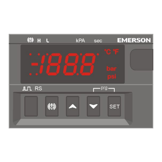
FRONT PANEL ................................................................................................................................. 2
6.
USER INTERFACE ........................................................................................................................... 2
7.
PARAMETER LIST ........................................................................................................................... 2
8.
DIGITAL INPUTS .............................................................................................................................. 2
9.
ELECTRICAL CONNECTIONS ........................................................................................................ 3
10. RS485 SERIAL LINE ........................................................................................................................ 3
11. USE THE HOT-KEY .......................................................................................................................... 3
12. ALARM MENU .................................................................................................................................. 3
13. DISPLAY MESSAGES ...................................................................................................................... 3
14. TECHNICAL DATA ........................................................................................................................... 3
15. STANDARD VALUES ....................................................................................................................... 3
1. GENERAL WARNING
1.1 PLEASE READ BEFORE USING THIS MANUAL
This manual is part of the product and should be kept near the instrument for easy and quick
•
reference.
The instrument shall not be used for purposes different from those described hereunder. It cannot
•
be used as a safety device.
Check the application limits before proceeding.
•
Emerson reserves the right to change the composition of its products, even without notice,
•
ensuring the same and unchanged functionality.
1.2 SAFETY PRECAUTIONS
Check the supply voltage is correct before connecting the instrument.
•
Do not expose to water or moisture: use the controller only within the operating limits avoiding
•
sudden temperature changes with high atmospheric humidity to prevent formation of condensation
Warning: disconnect all electrical connections before any kind of maintenance.
•
Fit the probe where it is not accessible by the End User. The instrument must not be opened.
•
In case of failure or faulty operation send the instrument back to the distributor or to Emerson with
•
a detailed description of the fault.
Consider the maximum current which can be applied to each relay (see Technical Data).
•
Ensure that the wires for probes, loads and the power supply are separated and far enough from
•
each other, without crossing or intertwining.
In case of applications in industrial environments, the use of mains filters (our mod. FT1) in parallel
•
with inductive loads could be useful.
2. GENERAL DESCRIPTION
The EC3-XEV02D is a slave module designed to be used with a master controller. It acts as a pure
transducer controller, receiving a regulating input from a master controller and transforming it in the
relative modulating signal for the digital unloader valve. The EC3-XEV02D module is equipped with a
temperature probe input (which could be an NTC86K or NTC/PT1000 type). It has a digital output (relay)
which is used for alarm or as compressor output, an open collector output which can be used as alarm
output and a modulating output (TRIAC type) to drive the unloader digital valve. There are also two
configurable digital inputs, the first one is free of voltage and the other ones is isolated in order to simplify
connections (high voltage input). The display permits to see the value of temperature or the control input
value or the output activation value in percentage. The local keyboard allows programming the
instrument without any other devices. To complete instrument equipment, a RS485 serial port permits
to connect the EC3-XEV02D to any modbus network and an HOT-KEY port to change configuration are
present.
3. WIRING CONNECTIONS
Please use the following scheme to make the right wirings.
NOTE:
-
The DIGITAL valve must be connected directly to terminals 23 and 24
-
The TRIAC output will work at the same power supply of the module
The high voltage digital input (D.I.2, terminals 8-9) works at the same voltage of the
-
Power Supply
EC3-XEV02D_OI_EN_0521_R00_866930.docx
4. ALARM FUNCTIONS
4.1 HIGH TEMPERATURE ALARM CONTROL (TRIP)
DLT alarm is generated when DLT probe (P2) temperature is: T >= dLt
Until alarm delay time (dLd) is active the total compressor capacity will be limited to Cdd.
If alarm delay time (dLd) is disabled or elapsed:
-
General alarm LED and digital output set as alarm (oAx = ALr) is activated
-
If a digital output is set as compressor output (oA1 = CPr) this is also deactivated.
-
If a digital output is set as demand output (oA1 = dmd) this is also deactivated.
-
Solenoid valve control output deactivates.
-
Buzzer activates (depending on the bEn parameter).
Alarm reset is automatic and happens when both of the following conditions occur:
-
Temperature measured by probe will be T ≤ dLt – dth and
Upon expiry of the stand-by timer for compressor head cooling (par. dCt).
-
In any case the regulation always re-starts after expiring both anti-short cycle timers 2on (minimum time
between two consecutive compressor activations) and 2oF (minimum time between one compressor
stop and next start-up).
Press any key to deactivate the buzzer at any time.
4.2 HIGH TEMPERATURE ALARM CONTROL (LOCKOUT)
DLT lockout alarm occurs after a dLn number of DLT alarms during the time interval (in hours) dLi.
The logic behind this control is as follows:
-
if dLn = 0, this control is deactivated (whatever the value of dLi);
-
if dLn ≠ 0 and dLi = 0, block occurs after a number of DLT alarms equal to dLn is had.
if dLn ≠ 0 and dLi ≠ 0, block occurs after a number of DLT alarms equal to dLn in time interval in
-
dLi (expressed in hours).
When the above-described condition occurs:
-
General alarm LED and digital output set as alarm (oAx = ALr) is activated.
-
If a digital output is set as compressor output (oA1 = CPr) this is also deactivated.
-
If a digital output is set as demand output (oA1 = dmd) this is also deactivated.
-
Solenoid valve control output deactivates.
-
Buzzer activates (depending on the bEn parameter).
Alarm reset is manual by means of controller on-off procedure or a special Modbus control.
In any case the regulation always re-starts after expiring both anti-short cycle timers 2on (minimum time
between two consecutive compressor activations) and 2oF (minimum time between one compressor
stop and next start-up).
Press any key to deactivate the buzzer at any time.
4.3 LOW TEMPERATURE ALARM CONTROL (LOCKOUT)
If the temperature probe P2 measures a lower value than the one set in parameter ALL and if this
condition persists for longer than the value set in parameter dLL:
General alarm LED and digital output set as alarm (oAx = ALr) is activated.
-
-
If a digital output is set as compressor output (oA1 = CPr) this is also deactivated.
-
Solenoid valve control output deactivates.
Buzzer activates (depending on the bEn parameter).
-
Alarm reset is manual by means of controller on-off procedure or by using a special MODBUS
command.
In any case the regulation always re-starts after expiring both anti-short cycle timers 2on (minimum time
between two consecutive compressor activations) and 2oF (minimum time between one compressor
stop and next start-up).
Press any key to deactivate the buzzer at any time
4.4 MISSING REGULATION SIGNAL CONDITION (TRIP)
A missing regulation signal alarm is generated if the control signal drops below the value set in the
parameter dSL (percentage value, if dSL = 0 this control is deactivated) and if this condition persists
longer than dEr seconds.
If so:
-
General alarm LED and digital output set as alarm (oAx = ALr) is activated.
-
If a digital output is set as compressor output (oA1 = CPr) this is also deactivated.
-
Solenoid valve control output deactivates.
-
Buzzer activates (depending on the bEn parameter).
EC3-XEV02D
1/3

Related Manuals for Emerson EC3-XEV02D


Summary of Contents for Emerson EC3-XEV02D
- Page 1 Alarm reset is manual by means of controller on-off procedure or a special Modbus control. The EC3-XEV02D is a slave module designed to be used with a master controller. It acts as a pure In any case the regulation always re-starts after expiring both anti-short cycle timers 2on (minimum time...
- Page 2 To erase the alarm database (when into alarm menu) Minimum load (in percentage): 0 - 100 % Maximum load (in percentage): 0 - 100 % 5.1 EC3-XEV02D LEDS DISPLAY On display there are some luminous dots. Their meaning is described in the following table: Default displayed variable: Per = TRIAC output activation in percentage;...
- Page 3 All models can be connected to a MODBUS network by using the 2-wire RS485 port. The XWEB related Precision a 25°C (77°F): ±0.7 °C ±1digit library and the MODBUS protocol can be issued on customer request from Emerson. 15. STANDARD VALUES 11.