Vaillant VR 91 Operating And Installation Instructions
Remote control unit
Hide thumbs
Also See for VR 91:
- System installation instructions (80 pages) ,
- Operating and installation instructions (16 pages) ,
- Schematics and installation manual (44 pages)
Table of Contents
Quick Links
Table of Contents
Troubleshooting

Related Manuals for Vaillant VR 91


Summary of Contents for Vaillant VR 91
- Page 1 Remote control unit VR 91 en Operating and installation instructions...
-
Page 2: Table Of Contents
Operating and Appendix ..........13 For the end user......13 installation instructions Operating modes ......13 Contents Operating levels......13 Troubleshooting ......15 Safety ..........3 For the competent person ..15 For the end user ......3 Installation assistant ....15 General safety information for Installer level........ -
Page 3: Safety
1 Safety not be carried out by children unless they are supervised. 1.1 For the end user Any other use that is not spe- 1.1.1 Intended use cified in these instructions, or In the event of inappropriate or use beyond that specified in this improper use, damage to the document, shall be considered product and other property may... -
Page 4: For The Competent Person
▶ If you cannot ensure the oper- mercial or industrial use is also ation, have a competent per- deemed to be improper. son drain the heating installa- Caution. tion. Improper use of any kind is prohibited. 1.3 For the competent person 1.3.1 Intended use 1.4 General safety information for... -
Page 5: Regulations (Directives, Laws, Standards)
1.5 Regulations (directives, laws, standards) ▶ Observe the national regula- tions, standards, directives, ordinances and laws. 0020200905_02 Operating and installation instructions... -
Page 6: For The End User
2.1.3 Validity of the instructions These instructions apply only to: 2.2.4 Data plate VR 91 – article number The data plate is located inside the product and is not accessible from the Great Britain 0020171334 outside. -
Page 7: Maintenance Message
Vaillant terms and con- 2.5 Fault message ditions. All requests for work during the guarantee period must be made to Vaillant If a fault occurs in the heating installation, Service Solutions. -
Page 8: Product Description
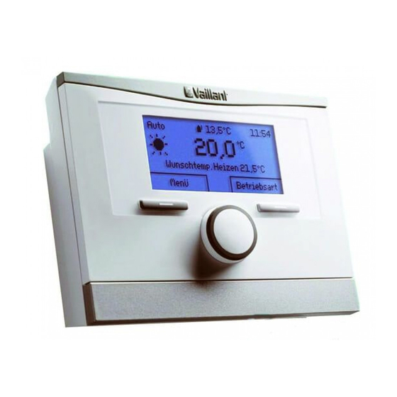
Meaning – Installation height: 1.5 m data plate Serial number for identification; 7th to 16th digits = product article number VR 91 Product designation Ø 6 Rated voltage Rated current Read the instructions 3.2.2 CE marking The CE marking shows that the products... -
Page 9: Electrical Installation
3.6 Start-up When you are operating the heating in- stallation for the first time after installing the electrical wiring, the installation assist- ants for the system components and the remote control unit start automatically. All settings that you have applied using the installation assistant can be changed again at a later date via the level for the end user and competent persons. -
Page 10: Handing Over To The End User
3.7 Handing over to the end user 3.9 Resetting to factory setting ▶ Inform the end user of how to handle You can use this function to reset all the and operate their product. set values that you configured using the ▶... -
Page 11: Troubleshooting
– You can use this function to read the 3.13 Recycling and disposal software versions of the remote control Packaging unit. ▶ Dispose of the packaging correctly. 3.10.3 Setting the address for the This product is an electrical or electronic remote control unit unit within the context of EU Directive 2012/19/EU. -
Page 12: Customer Service
If the product contains personal data: ▶ Ensure that there is no personal data on or in the product (e.g. online login details or similar) before you dispose of the product. 3.14 Customer service Customer service addresses can be found in the installation instructions for the sys- tem control. -
Page 13: Appendix
Appendix A For the end user A.1 Operating modes Operating mode Setting Default setting Operating mode Heating off, Auto, Day, Set-back Auto Cooling off, Auto, Day Auto Advanced functions – 1 day at home active – 1 day away from home active –... - Page 14 Setting level Values Unit Increment, select Default setting Min. Max. Time programmes → ZONE1: Heating → Individual days and Monday, Tues- Mo - Fr: blocks day, Wednesday, 06:00- Thursday, Friday, 22:00 Saturday, Sunday Sa: 07:30- and Monday - Fri- 23:30 day, Saturday - Su: 07:30- Sunday, Monday -...
-
Page 15: Troubleshooting
Setting level Values Unit Increment, select Default setting Min. Max. Basic settings → Enter zone name → ZONE1 A to Z, 0 to 9, space ZONE1 Installer level → Enter code A.3 Troubleshooting Symptom Possible cause Measure Display remains dark Software error Switch off the mains switch on all heat generators for approx. -
Page 16: Installer Level
B.2 Installer level Setting level Values Increment, select Default setting Min. Max. Installer level → Enter code Installer level → System configuration → System ---- Fault status Current value* Control modules Display Software version Remote control address * If no fault is present, the status is No fault. If there is a fault, Fault list appears and you can read the fault message in the "Fault messages"... - Page 17 Symptom Possible cause Measure Lines appear instead Communication fault Check the plug connection. of set and read-out Replace the cable. values 0020200905_02 Operating and installation instructions...
- Page 20 Supplier Vaillant Ltd. Nottingham Road Belper Derbyshire DE56 1JT Telephone 0330 100 3143 [email protected] www.vaillant.co.uk 0020200905_02 Publisher/manufacturer Vaillant GmbH Berghauser Str. 40 D-42859 Remscheid Tel. +49 2191 18 0 Fax +49 2191 18 2810 [email protected] www.vaillant.de © These instructions, or parts thereof, are protected by copyright and may be reproduced or distributed only with the manufacturer's written consent.