Dell Dimension C521 Service Manual
Hide thumbs
Also See for Dimension C521:
- Setting up (2 pages) ,
- Owner's manual (140 pages) ,
- Service manual (51 pages)
Table of Contents
Quick Links
Dell™ Dimension™ C521 Service Manual
Before You Begin
About Your Computer
Technical Overview
Removing the Computer Cover
Specifications
Troubleshooting
System Setup
Removing and Installing Parts
Replacing the Computer Cover
Notes, Notices, and Cautions
NOTE:
A NOTE indicates important information that helps you make better use of your computer.
NOTICE:
CAUTION:
Information in this document is subject to change without notice.
© 2006 Dell Inc. All rights reserved.
Reproduction in any manner whatsoever without the written permission of Dell Inc. is strictly forbidden.
Trademarks used in this text: Dell, the DELL logo, and Dimension are trademarks of Dell Inc.; AMD, AMD Athlon, and combinations thereof, Sempron, and Cool 'n' Quiet are
trademarks of Advanced Micro Devices, Inc; Microsoft and Windows are registered trademarks of Microsoft Corporation.
Other trademarks and trade names may be used in this document to refer to either the entities claiming the marks and names or their products. Dell Inc. disclaims any
proprietary interest in trademarks and trade names other than its own.
September 2006 Rev. A00
Great user manuals database on
A NOTICE indicates either potential damage to hardware or loss of data and tells you how to avoid the problem.
A CAUTION indicates a potential for property damage, personal injury, or death.
UserManuals.info
Table of Contents

Related Manuals for Dell Dimension C521


Summary of Contents for Dell Dimension C521
- Page 1 Advanced Micro Devices, Inc; Microsoft and Windows are registered trademarks of Microsoft Corporation. Other trademarks and trade names may be used in this document to refer to either the entities claiming the marks and names or their products. Dell Inc. disclaims any proprietary interest in trademarks and trade names other than its own.
-
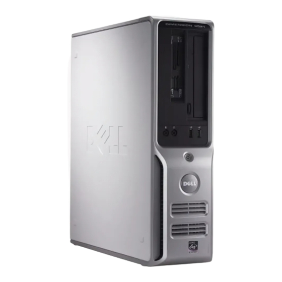
Page 2: About Your Computer
Use this latch to remove the cover. See Removing the Computer Cover. latch Service Tag Use to identify your computer when you access the Dell Support website or call support. FlexBay drive Can contain an optional floppy drive or optional Media Card Reader. CD or DVD... -
Page 3: Back View Of The Computer
NOTICE: Ensure that there is a minimum of two inches of space between all vents and any object near these vents. NOTICE: Keep the vent area clean and dust-free to ensure that the system is adequately ventilated. Use only a dry cloth to clean the vent area to avoid water damage to the system. - Page 4 NOTE: It is recommended that you use Category 5 wiring and connectors for your network. If you must use Category 3 wiring, force the network speed to 10 Mbps to ensure reliable operation. network activity Flashes a yellow light when the computer is transmitting or light receiving network data.
-
Page 5: Before You Begin
Hold a component such as a processor by its edges, not by its pins. NOTICE: Only a certified service technician should perform repairs on your computer. Damage due to servicing that is not authorized by Dell is not covered by your warranty. - Page 6 NOTICE: To disconnect a network cable, first unplug the cable from your computer and then unplug it from the network port or device. 2. Disconnect any telephone or network cables from the computer. 3. Disconnect your computer and all attached devices from their electrical outlets, and then press the power button to ground the system board. ...
-
Page 7: Replacing The Computer Cover
Back to Contents Page Replacing the Computer Cover Dell™ Dimension™ C521 Service Manual CAUTION: Before you begin any of the procedures in this section, follow the safety instructions located in the Product Information Guide. 1. Ensure that all cables are connected, and fold cables out of the way. -
Page 8: Removing The Computer Cover
Back to Contents Page Removing the Computer Cover Dell™ Dimension™ C521 Service Manual CAUTION: Before you begin any of the procedures in this section, follow the safety instructions in the Product Information Guide. CAUTION: To guard against electrical shock, always unplug your computer from the electrical outlet before opening the cover. -
Page 9: Removing And Installing Parts
2 Channel B: matched pair of memory modules in connectors DIMM_1 and modules in connectors DIMM_3 and DIMM_2 (white securing clips) DIMM_4 (black securing clips) NOTE: Memory purchased from Dell is covered under your computer warranty. Great user manuals database on UserManuals.info... -
Page 10: Installing Memory
If you remove your original memory modules from the computer during a memory upgrade, keep them separate from any new modules that you may have, even if you purchased the new modules from Dell. If possible, do not pair an original memory module with a new memory module. -
Page 11: Removing Memory
To prevent static damage to components inside your computer, discharge static electricity from your body before you touch any of your computer's electronic components. You can do so by touching an unpainted metal surface on the computer chassis. Your Dell™ computer provides the following slots for PCI and PCI Express cards: One low-profile PCI card slot One low-profile PCI Express x1 and x16 card slot... -
Page 12: Installing An Expansion Card
Installing an Expansion Card 1. Follow the procedures in Before You Begin. 2. Gently push the release tab on the inside of the card retention door to pivot the door open. Because the door is captive, it will remain in the open position. -
Page 13: Removing An Expansion Card
release tab card retention door filler bracket alignment guide alignment bar 8. Close the card retention door by snapping it into place. NOTICE: Do not route card cables over the cards. Cables routed over the cards can prevent the computer cover from closing properly or cause damage to the equipment. - Page 14 PCI Express x16 card lever securing slot securing tab PCI Express x16 card connector 6. If you are removing the card permanently, install a filler bracket in the empty card-slot opening. NOTE: Installing filler brackets over empty card-slot openings is necessary to maintain FCC certification of the computer. The brackets also keep dust and dirt out of your computer.
-
Page 15: General Installation Guidelines
DVD drive optional floppy drive or media card reader hard drive General Installation Guidelines Connect the SATA hard drive to the connector labeled "SATA0." Connect the SATA CD or DVD drives to the connector labeled "SATA1" on the system board. ... -
Page 16: Removing A Cd/Dvd Drive
CD/DVD Drive CAUTION: Before you begin any of the procedures in this section, follow the safety instructions located in the Product Information Guide. CAUTION: To guard against electrical shock, always unplug your computer from the electrical outlet before removing the cover. ... -
Page 17: Removing A Floppy Drive
b. Remove the three shoulder screws from the drive-panel insert. 4. If you are replacing an existing drive: a. Remove the existing drive. b. Remove the three shoulder screws from the existing drive. 5. Insert the three shoulder screws into the sides of the new drive and tighten them. ... -
Page 18: Installing A Floppy Drive
drive release latch floppy drive 4. Disconnect the power and data cables from the back of the floppy drive. 5. Replace the computer cover. See Replacing the Computer Cover. NOTICE: To connect a network cable, first plug the cable into the network port or device, and then plug it into the computer. ... -
Page 19: Removing A Media Card Reader
floppy drive slot verification number 8. Slide the drive into the bay until it clicks into place. 9. Connect the data cable to the connector labeled "FLOPPY" on the system board. Replace the CD/DVD drive. 11. Check all cable connections, and fold cables out of the way to provide airflow for the fan and cooling vents. ... -
Page 20: Installing A Media Card Reader
Media Card Reader drive release latch 5. Replace the computer cover. See Replacing the Computer Cover. NOTICE: To connect a network cable, first plug the cable into the network port or device, and then plug it into the computer. ... -
Page 21: Removing A Hard Drive
Media Card Reader slot verification number 7. Slide the Media Card Reader into the bay until it clicks into place. 8. Connect the power and data cables to the back of the Media Card Reader. 9. Connect the data cable to the USB connector on the system board. ... -
Page 22: Installing A Hard Drive
securing clips (2) hard drive Installing a Hard Drive 1. Check the documentation for the drive to verify that it is configured for your computer. NOTICE: To avoid damage to the drive, do not set it on a hard surface. Instead, set the drive on a surface, such as a foam pad, that will sufficiently cushion it. -
Page 23: Replacing The Battery
15. Partition and logically format your drive before you proceed to the next step. For instructions, see the documentation that came with your operating system. 16. Test the hard drive by running the Dell Diagnostics. See Dell Diagnostics. ... -
Page 24: Removing The Processor
To replace the battery: 1. Record all of the settings in system setup (see System Setup Options) so that you can restore the correct settings in step 8. 2. Follow the procedures in Before You Begin. 3. Locate the battery socket. ... -
Page 25: Installing The Processor
heat sink assembly captive screws (2) NOTICE: Unless a new heatsink is required for the new processor, reuse the original heat sink assembly when you replace the processor. 4. Pull the release lever straight up until the processor is released. processor release lever socket... - Page 26 2. Unpack the new processor, being careful not to bend any of the processor pins. NOTE: You must position the processor correctly in the socket to avoid permanent damage to the processor and the computer when you turn on the computer.
-
Page 27: Replacing The Power Supply
heat sink assembly heat-sink assembly bracket captive screws (2) 10. Replace the computer cover. See Replacing the Computer Cover. NOTICE: To connect a network cable, first plug the cable into the network port or device and then plug it into the computer. ... -
Page 28: Removing The Front I/O Panel
release button power supply screws (2) AC power connector 5. Slide the power supply toward the front of the computer and lift the power supply up and out of the computer. 6. Lower the replacement power supply into the computer. ... -
Page 29: Installing The Front I/O Panel
6. Disconnect the cable attached to the front I/O panel. 7. Remove the screw that secures the front I/O panel to the chassis. 8. Rotate the I/O panel toward the back of the computer and remove and the I/O panel from the computer. securing tab screw I/O panel bracket... -
Page 30: Installing The Fan Assembly
CAUTION: The heat-sink assembly can get very hot during normal operation. Be sure that the assembly has had sufficient time to cool before you touch it. 4. Disconnect the fan power cable from the FAN_CPU1 connector on the system board. See System Board Components. fan tabs (2) fan release lever fan cable connector... -
Page 31: Replacing The System Board
Replacing the Computer Cover. 9. Connect your computer and devices to electrical outlets, and turn them on. 10. Verify the computer is operational by running the Dell Diagnostics. See Dell Diagnostics. Back to Contents Page Great user manuals database on... - Page 32 Great user manuals database on UserManuals.info...
-
Page 33: Specifications
Back to Contents Page Specifications Dell™ Dimension™ C521 Service Manual Microprocessor Microprocessor type AMD™ Athlon™ 64 X2 Dual-Core processor AMD Athlon 64 AMD Sempron™ Internal L2 cache up to 1 MB per core up to 256 KB for Sempron Memory Type 533-MHz, 667-MHz, 800-MHz z (when available) DDR2... - Page 34 card size low profile connector size 124 pins connector data width 32 bits (maximum) PCI Express: connectors one x1 and one x16 power 10 W (x1) and 25 W (x16) maximum connector size 36 pins (x1) and 164 pins (x16) connector data width (maximum) one PCI Express lane (x1) and 16 PCI Express lanes (x16)
- Page 35 Power DC power supply: Wattage 280 W Heat dissipation 955.39 BTU/hr maximum NOTE: Heat dissipation is calculated based upon the power supply wattage rating. Voltage manual selection power supply — 90 to 135 V at 50/60 Hz; 180 to 265 V at 50/60 Hz Backup battery 3-V CR2032 lithium coin cell ...
-
Page 36: Entering System Setup
Entering System Setup 1. Turn on (or restart) your computer. 2. When the blue DELL™ logo is displayed, you must watch for the F2 prompt to appear. 3. Once this F2 prompt appears, pressimmediately. NOTE: The F2 prompt indicates that the keyboard has initialized. This prompt can appear very quickly, so you must watch for it to display, and then press . -
Page 37: System Setup Options
and lists keys and their functions within the active system setup field. System Setup Options NOTE: Depending on your computer and installed devices, the items listed in this section may not appear, or may not appear exactly as listed. System Lists the computer name, BIOS Version, Service Tag, Express Service Code, (if applicable), and the Asset Tag. - Page 38 (Auto default) NOTE: A PCI Express graphics card will override the integrated video controller. This setting configures the amount of system memory that is reserved for the integrated video controller. The settings are Auto, 16MB, Video Memory 32MB, 64MB, 128MB, or Off. Size (64MB default)
-
Page 39: Option Settings
Restores system setup options to their factory defaults. Load Defaults Allows you to view the Event Log. Entries are marked R for Read and U for Unread. Mark All Entries Read puts an R to the left of all the Event Log entries. -
Page 40: Clearing Forgotten Passwords And Cmos Settings
1. Enter system setup, select Boot Sequence from the System group. See System Setup Options. 2. Pressto access the menu. NOTE: Write down your current boot sequence in case you want to restore it. 3. Press the up- and down-arrow keys to highlight the appropriate Boot Sequence option. ... -
Page 41: Clearing Cmos Settings
The BIOS may require a new flash when an update is available or when replacing the system board. 1. Turn on the computer. 2. Locate the BIOS update file for your computer at support.dell.com. 3. Click Download Now to download the file. ... -
Page 42: Technical Overview
Back to Contents Page Technical Overview Dell™ Dimension™ C521 Service Manual Inside View of Your Computer System Board Components Power Supply DC Connector Pin Assignments Inside View of Your Computer CAUTION: Before you begin any of the procedures in this section, follow the safety instructions in the Product Information Guide. -
Page 43: Jumper Settings
fan connector processor socket memory module connectors (FAN_CPU1) (CPU) (DIMM_1, DIMM_2, DIMM_3, DIMM_4) power connector power connector SATA drive connectors (SATA0, (PW_12V_A1) (POWER1) SATA1) front-panel connector CMOS reset battery socket (BT1) (FRONTPANEL) (RTCRST) 10 internal USB (USB1) 11 PCI Express x16 12 PCI Express x1 connector connector (SLOT1) (SLOT2) -
Page 44: Power Supply Dc Connector Pin Assignments
The real-time clock is being reset (jumpered temporarily). jumpered unjumpered Power Supply DC Connector Pin Assignments DC Power Connector P1 Pin Number Signal name 18-AWG Wire +3.3 VDC Orange +3.3 VDC Orange Black VCC (+5 V) Black VCC (+5 V) Black... -
Page 45: Dc Power Connector P2
VCC (+5V) Black *Use 22-AWG wire instead of 18-AWG wire. DC Power Connector P2 Pin Number Signal Name 18-AWG Wire Black Black +12 VDC Yellow +12 VDC Yellow DC Power Connector P3 Pin Number Signal name 18-AWG Wire... - Page 46 +5 VDC Black +12 VDC Yellow Back to Contents Page Great user manuals database on UserManuals.info...
-
Page 47: Notes, Notices, And Cautions
Advanced Micro Devices, Inc; Microsoft and Windows are registered trademarks of Microsoft Corporation. Other trademarks and trade names may be used in this document to refer to either the entities claiming the marks and names or their products. Dell Inc. disclaims any proprietary interest in trademarks and trade names other than its own. -
Page 48: Troubleshooting
If you cannot resolve the error condition, contact Dell. For information about contacting Dell, see your Owner's Manual. NOTE: The Service Tag for your computer is located at the top of each test screen. If you contact Dell, technical support will ask for your Service Tag. ... -
Page 49: System Lights
Parameters Allows you to customize the test by changing the test settings. Close the test screen to return to the Main Menu screen. To exit the Dell Diagnostics and restart the computer, close the Main Menu screen. System Lights Your power button light and hard-drive activity light may indicate a computer problem. -
Page 50: Beep Codes
System Lights. system starts. If there are no power problems and the system does not start, contact Dell. For information about contacting Dell, see your Owner's Manual. NOTE: If all of the diagnostic lights are on...