Table of Contents
Quick Links
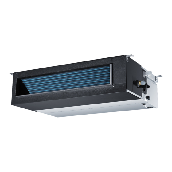
Medium Static
Installation Instructions
Duct Indoor
Design may vary by model number.
L'aspect peut varier selon le numéro de modèle.
El diseño puede variar según el número
This installation manual is only
Ce manuel d'installation est uniquement
de model. Este manual de instalación sólo
printed in English. For French or
imprimé en anglais. Pour la version française ou
fue impreso en inglés. Para acceder a la
Spanish version, please visit
espagnole, visitez le site
versión en francés o español, por favor visite
GEAppliancesairandwater.com
GEAppliancesairandwater.com
GEAppliancesairandwater.com
31-5000493 Rev. 4 03-23 GEA
NO:0150560531
Table of Contents

Related Manuals for Haier GE USYM09UCDSA


Summary of Contents for Haier GE USYM09UCDSA
- Page 1 Medium Static Installation Instructions Duct Indoor Design may vary by model number. L’aspect peut varier selon le numéro de modèle. El diseño puede variar según el número This installation manual is only Ce manuel d’installation est uniquement de model. Este manual de instalación sólo printed in English.
-
Page 2: Table Of Contents
Date of purchase Staple your proof of purchase to this manual to aid in obtaining warranty service if needed. To register your new Haier Duct Free System go to Haierductless.com/product-registration or GEAppliances.com/ductless/registration-form and input the model/serial number information on this page. To receive a 10-year compressor and parts warranty, registration is required within 60 days of installation. -
Page 3: Important Safety Information
• These R-410A heat pumps systems require that • Any servicing must be performed by a qualified contractors and technicians use tools, equipment and individual. GE Appliances/Haier recommends factory safety standards approved for use with this refrigerant. trained and service & installation contractors that meet DO NOT use equipment certified for R22 refrigerant local and national code requirements for the region. -
Page 4: Installation Instructions
Installation Instructions FOR MORE HELP, VISIT HAIERAPPLIANCES.COM/DUCTLESS OR GEAPPLIANCES.COM/DUCTLESS BEFORE YOU BEGIN CAUTION Read these instructions completely and carefully. • Aluminum building wiring may present special problems - consult a qualified electrician. IMPORTANT – • Save these instructions • When the unit is in the STOP position, there is still for local inspector’s use. -
Page 5: Parts Included
Installation Instructions: List of Materials Required Tools for Installation • 17mm, 22mm, 26mm or Adjustable Wrench • Razor Knife • #2 Phillips Screwdriver • Reamer • Drill • Sealant, non-expanding (for line set opening) • R-410A Approved Flaring Tool • HVAC leak solution or refrigerant leak detector •... -
Page 6: Ducted Product Information
Installation Instructions: Introduction and Overview Ducted Product Information The Ducted unit will install above the ceiling or in a soffit area. It is mounted using threaded rods that fit into brackets that are located at all four top corners of the cabinet. - Page 7 Installation Instructions: Introduction and Overview Condensate Handling Electrical Power The Ducted unit has a built-in condensate pump and Follow all local codes and regulations when installing high water level safety switch. There are also two electrical wiring. optional ports for gravity drainage. Route required electrical power to area where the The condensate pump is rated to lift water up to 27”...
-
Page 8: Step 1: Preparation
Installation Instructions MINIMUM CLEARANCES AND DIMENSIONS (Appearance may vary) Air Delivery Clearances Service and Maintenance Clearances Make certain to maintain proper clearances around the Make sure there are adequate clearances for future Ducted unit. maintenance and service. Allow enough room to access the condensate pump assembly and the electrical Inadequate clearances can cause system operation and control box. -
Page 9: Step 2: Mounting The Unit
Installation Instructions Step 1 - Preparation (cont) Step 2 - Mounting the Unit B. Unit Hanging Information: Determine location and use the template (shipped in the box) to mark the location of threaded rods. Install The Ducted unit should be mounted to the building the hardware necessary to mount the threaded rods. - Page 10 Installation Instructions Step 2 - Mounting the Unit (Cont.) Cont. Continued. Tighten the flares with a torque wrench and back-up wrench as defined by the table below. Forced fastening without careful centering will damage the threads and cause a refrigerant leak. Pipe Diameter (ø) Fastening torque 1/4”...
-
Page 11: Step 3: Electrical Connections
Installation Instructions Step 2 - Mounting the Unit (Cont.) Step 3 - Electrical Connections Electrical Connections Indoor and Outdoor DIP Switch Settings Units The DIP switch bank on the PCB need to be checked. Need to make sure all switches are in the correct position including 14/4 non-shielded stranded copper cable only. -
Page 12: Optional Special Application 1: Auxiliary Heat
Installation Instructions Optional Control Functions The air handler supports the ability to (1) activate or deactivate auxiliary ducted heaters (by others) and to (2) activate or deactivate external air dampers (by others) for drawing in outside air. 1) Auxiliary Heater Interface Instructions Auxiliary ducted heaters should be sized to fit the supply plenum and avoid bypass air connections. -
Page 13: Optional Special Application 2: Outside Air Damper Installation
Installation Instructions Optional Control Functions 2) Outside Air Damper Interface Instructions Source a 4” diameter normally closed damper by others to regulate the supply of outdoor air. Install damper as per manufacturers recommendations. To control the operation of the outdoor air damper with the air handler, use this procedure to interface the two systems: •... -
Page 14: Final Check
Installation Instructions Final Check Start Up Checklist □ □ Refrigerant charge is verified and system has been Check reservoir for any contaminates from installation leak tested that could promote bacteria growth □ □ Line sets have been insulated Indoor and outdoor units are compatible □... -
Page 15: Limited Warranty
/ air handler). • Labor and related services for repair or installation of the • Component or parts are not provided by GE Appliances, a Haier Product. Company • A product purchased from an unauthorized online retailer. - Page 16 GE Appliances, a Haier company, Louisville, KY 40225. ATTACHMENT 1 The “Product” is defined as Haier brand and GE Appliances brand Ductless Split Units and Side-discharge Units. The “Product” contains 2 sub-categories of goods: “Indoor and Outdoor Products” and “Selected Installation Products,”...