Table of Contents
Quick Links
AUUB18TLAV1
AUUB24TLAV1
AUUB30TLAV1
AUUB36TLAV1
AUUB48TLAV1
TM
INSTALLATION MANUAL
MANUEL D'INSTALLATION
MANUAL DE INSTALACIÓN
Únicamente para personal de servicio autorizado.
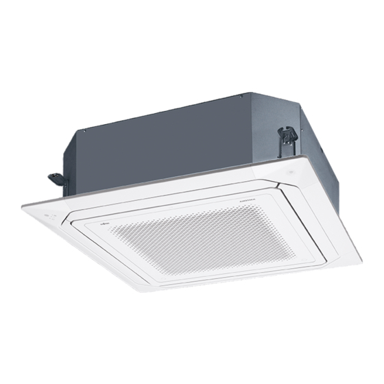
INDOOR UNIT (Cassette Type)
For authorized service personnel only.
UNITÉ INTÉRIEURE (type cassette)
Pour le personnel agréé uniquement.
UNIDAD INTERIOR (Tipo casete)
PART No. 9371022574
Table of Contents

Related Manuals for Fujitsu AIRSTAGE AUUB18TLAV1


Summary of Contents for Fujitsu AIRSTAGE AUUB18TLAV1
- Page 1 INSTALLATION MANUAL INDOOR UNIT (Cassette Type) For authorized service personnel only. MANUEL D’INSTALLATION UNITÉ INTÉRIEURE (type cassette) Pour le personnel agréé uniquement. MANUAL DE INSTALACIÓN UNIDAD INTERIOR (Tipo casete) Únicamente para personal de servicio autorizado. AUUB18TLAV1 AUUB24TLAV1 AUUB30TLAV1 AUUB36TLAV1 AUUB48TLAV1 PART No.
-
Page 2: Table Of Contents
INSTALLATION MANUAL 1.2. SPECIAL PRECAUTIONS PART No. 9371022574 VRF system indoor unit (Cassette type) When Wiring Contents ELECTRICAL SHOCK CAN CAUSE SEVERE PERSONAL INJURY OR DEATH. ONLY A SAFETY PRECAUTIONS ..................1 QUALIFIED, EXPERIENCED ELECTRICIAN SHOULD ATTEMPT TO WIRE THIS SYSTEM. 1.1. -
Page 3: About This Product
Name and Shape Q’ty Application All Fujitsu General products are manufactured to metric units and tolerances. United Operation manual States customary units are provided for reference only. In cases where exact dimensions and tolerances are required, always refer to metric units. -
Page 4: Installation Work
Discharge direction setting 3. INSTALLATION WORK • The discharge direction can be selected as shown below. 4 direction 3 direction Correct initial installation location is important because it is difficult to move unit after it is installed. 3.1. Selecting an installation location Decide the mounting position together with the customer as follows. -
Page 5: Pipe Installation
(2) Setting the positions of hanging bolt and ceiling opening. • Thicknesses of copper pipes used with R410A are as shown in the table. • Use an installation template (packaging top surface) to set the positions of the hanging • Never use copper pipes thinner than those indicated in the table even if they are avail- bolt and ceiling opening and drill holes. -
Page 6: Installing Heat Insulation
4.3.2 Bending pipes 5. INSTALLING DRAIN PIPES • If pipes are shaped by hand, be careful not to collapse them. • Do not bend the pipes in an angle more than 90°. • When pipes are repeatedly bent or stretched, the material will harden, making it difficult WARNING to bend or stretch them anymore. -
Page 7: Electrical Wiring
Install the knob Securely connect the connection cables to the terminal board. In addition, secure the Attached hose band faces upward (Accessories) cables with wiring holders. Improper connections, either in the wiring or at the ends of Locally arranged the wiring, can cause a malfunction, electric shock, or fire. vinyl pipe Attached drain hose Always fasten the outside covering of the connection cable with the cable clamp. -
Page 8: Wiring Method
6.1.1 Cable specifi cations Strip 1 in (25 mm) Cable size Cable type Remarks LEVEL 4 (NEMA) non-polar Transmission 22 AWG LONWORKS ® Loop 2 core, twisted pair solid core cable (0.33 mm²) compatible cable diameter 0.026 in (0.65mm) 22 AWG to 16 AWG Non polar 2 core, Sheathed PVC cable Remote con-... -
Page 9: Connection Of Wiring
(2) Please firmly tighten Connection cable and Remote controller cable with the attached Terminal number Tightening torque cable tie. M3 screw (Transmission /X1, X2) 4.4 to 5.3 Ibf·in (0.5 to 0.6 N·m) (Remote controller /Y1, Y2) X1, X2: Transmission cable CAUTION To peel the film from the lead cable, use a dedicated tool that will not damage the conductor cable. -
Page 10: Optional Parts Wiring
● Apply voltage terminal ([CNA01], [CNA03]) 6.5. Optional parts wiring When a power supply must be provided at the input device you want to connect, use the Apply voltage terminal ([CNA01], [CNA03]). 6.5.1 Connector and DIP switch position Output terminal Apply voltage terminal DC power supply P.C.B... -
Page 11: Field Setting
● Forced thermostat off function When connected to Dry contact terminals of multiple indoor units with a connected unit, insulate each indoor unit with relay, etc. as shown on below example. [“Edge” input only] Connector Input signal Command P.C.B OFF → ON Thermostat off Ch3 of CNA03 or CNA04 ON →... -
Page 12: Setting The Address
• Custom code setting for indoor unit 7.1. Setting the address IU AD REF AD RC AD Set the DIP switch SET3 SW1, 2, referring to the figure and table below. ×10 ×1 ×10 ×1 CAUTION Use an insulated screwdriver to set the dip switches. SET3 SET4 •... -
Page 13: Cassette Grille Installation
Function 8. CASSETTE GRILLE INSTALLATION Function Setting number Default Details number Follow the When set to 01, the fan stops • Operate according to the installation Manual CASSETTE GRILLE. Fan set- when the thermostat is OFF in setting on • Be sure to confirm there is no gap between the cassette grille and main unit after install- ting when cooling operation. -
Page 14: Error Codes
11. ERROR CODES If you use a wired type remote controller, error codes will appear on the remote controller display. If you use a wireless remote controller, the lamp on the photodetector unit will output error codes by way of blinking patterns. See the lamp blinking patterns and error codes in the table below.