Table of Contents
Quick Links
Table of Contents

Related Manuals for Electro-Voice X-LINE ADVANCE Series


Summary of Contents for Electro-Voice X-LINE ADVANCE Series
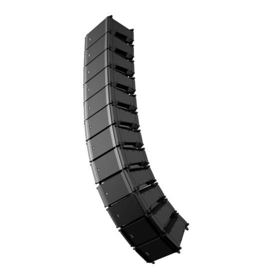
- Page 1 X‑LINE ADVANCE System Rigging & Transport Installation manual...
-
Page 3: Table Of Contents
Short Information System overview Designing an X-Line Advance speaker system array Applications for which X-Line Advance arrays are most appropriate Electro-Voice line array configuration software Preparing X-Line Advance elements for installation Unpacking and inspection Scope of delivery Recommended preflight procedures... - Page 4 Rigging structural strength ratings and safety factors 10.1 Structural introduction 10.2 Structural rating overview 10.3 Electro-Voice line array configuration software structural evaluations simplified structural rating guidelines 10.4 Specific safety considerations 10.5 Working-load limit and safety factor definitions Rigging inspection and precautions Technical data 12.1...
-
Page 5: Safety
X-Line Advance product family from Electro-Voice. It is intended to familiarize the user with standard rigging hardware and techniques for suspending X-Line Advance loudspeaker systems overhead. Only persons with the knowledge of proper hardware and safe rigging techniques should attempt to suspend any sound systems overhead. -
Page 6: Important Safety Instructions
Any hardware used to suspend a loudspeaker not associated with Electro-Voice is the responsibility of others. Precautions These Electro-Voice loudspeakers were designed for use in an environment with ambient temperatures between -20°C (-4°F) and +50°C (122°F). These Electro-Voice loudspeakers are not rated for continuous outdoor conditions. - Page 7 For information on getting permission for reprints and excerpts, contact Electro-Voice. All content including specifications, data, and illustrations in this manual are subject to change without prior notice.
-
Page 8: Short Information
Grill kit X12-125F as cardioid element X12T-DOLLY Dolly for X1/X2, 6 tops per dolly X12-125F-DOLLY Dolly for X12-125F flying subwoofers X12-125F-DAK Adapter kit, X12-125F-DOLLY to X1/X2 X12-125F-DOK Outrigger kit for X12-125F-DOLLY X12-128-DOLLY Dolly for X12-128 non-flying subwoofers 2019-07 | 04 | F.01U.310.953 Electro-Voice Installation manual... -
Page 9: System Overview
X12-128 is a compact rectangular dual-18-inch subwoofer element designed for use only as a ground stack subwoofer array. It may be configured in multiple subwoofer array configurations, including cardioid, end fired and others. Electro-Voice 2019-07 | 04 | F.01U.310.953 Installation manual... - Page 10 Accessories: Grids The X-Line Advance grid options are sold separately. Consult Electro-Voice line array configuration software for proper grid selection and array design. X12TC-GRID: Standard compact grids for up to 24 X1 or X2 elements for simple or mostly straight arrays, where extreme tilt angles are not required.
- Page 11 X12-128-DOLLY is used for transporting X12-128 subwoofers. The dolly will accommodate one column of X12-128 subwoofers stacked two high for transportation. The systems should be secured with ratchet straps (included) for additional protection during transport. Electro-Voice 2019-07 | 04 | F.01U.310.953 Installation manual...
-
Page 12: Designing An X-Line Advance Speaker System Array
Electro-Voice line array configuration software Acoustic design techniques are outside the scope of this document. For acoustic design assistance, the reader is directed to the Electro-Voice line array configuration software available for download from the Electro-Voice website www.electrovoice.com. This software will guide the user through design considerations to make the best choice of loudspeakers and loudspeaker array configurations for a specific venue application. -
Page 13: Preparing X-Line Advance Elements For Installation
Element configuration After using Electro-Voice line array configuration software to design an appropriate array, it is recommended all necessary hardware and accessories to suspend the array are checked and accounted for. Ensure all hardware is in good working order, no defects, damage or imperfections are present, and all hardware is capable of meeting or exceeding the total load requirements of the entire array. -
Page 14: Rigging System
In this section, the rigging steps illustrated with X1/X2 full-range drawings are performed the same way for the X12-125F subwoofer. Rigging differences between the X1/X2 full-range elements and the X12-125F subwoofer are noted in the steps, when applicable. 2019-07 | 04 | F.01U.310.953 Electro-Voice Installation manual... -
Page 15: Setting Rear Link Angles
The rear link angle is selected by choosing corresponding holes in the white ANGLE SELECT sections of the rear rigging on each side as determined by the Electro-Voice line array configuration software. Unless the rigging is locked into a rigid configuration by secondary pins in the lower black ANGLE LOCK sections, the elements always default to 0°... - Page 16 PIN PARK is used to store or park the unused pin when an angle is not set for the element. RETRACT LOCK is used to lock the link bar in the stored position. (X1 or X2 full-range only) 2019-07 | 04 | F.01U.310.953 Electro-Voice Installation manual...
-
Page 17: Single Pin And Double Pin
To single pin or double pin, do the following: Release the quick-release pin from RETRACT LOCK hole. This step applies to the full-range X1/X2 loudspeakers. Release the quick-release pin from 0° EVEN hole. This step applies to the X12-125F subwoofer. Electro-Voice 2019-07 | 04 | F.01U.310.953 Installation manual... - Page 18 If using double pin continue to the next step. Lower the element until its weight is resting on the angle select pins. 10. Insert the second quick-release pin into desired ANGLE LOCK hole. 2019-07 | 04 | F.01U.310.953 Electro-Voice Installation manual...
- Page 19 13. Verify both pins are pushed in all the way and the blue buttons are not depressed. 14. Repeat this process on all elements in the array setting the angles per the report from Electro-Voice line array configuration software. Electro-Voice 2019-07 | 04 | F.01U.310.953...
-
Page 20: Transportation Dollies
X12-125F-DOLLY accommodates one column of X12-125F subwoofers stacked two high when both subwoofers are facing forward or three high when in cardioid configuration (two forward facing and one backward facing) for transportation. 2019-07 | 04 | F.01U.310.953 Electro-Voice Installation manual... -
Page 21: Stacking X1, X2, And X12-125F Elements Onto A Dolly
ANGLE SELECT section. Compress the rear link bars until they contact the angle select pin and lock by adding a second pin in the EVEN holes of the ANGLE LOCK section. Ensure the two front link bars are lowered and locked. Electro-Voice 2019-07 | 04 | F.01U.310.953 Installation manual... - Page 22 On the next element, extend and lock the two front link bars. Extend and lock the two rear link bars at 0° EVEN. 10. Guide the next element (E) onto the stack. X12T-DOLLY X12-125F-DOLLY 2019-07 | 04 | F.01U.310.953 Electro-Voice Installation manual...
- Page 23 Twist and lock the captive twist lock pin at the front of the element. The captive twist lock pin at the front of the element should now be in the closed position with the front link bar extended. Electro-Voice 2019-07 | 04 | F.01U.310.953 Installation manual...
- Page 24 13. Verify both pins are pushed in all the way and the blue buttons are not depressed. 14. Orient the next element to align the front with the rear of the previously installed element. 2019-07 | 04 | F.01U.310.953 Electro-Voice Installation manual...
-
Page 25: X12T-Dolly Side Panels And Top Cover
Ensure the top two captive twist lock pins are open on both loudspeakers on the stack. Guide the link bars of the dolly top cover into the V-blocks of the loudspeaker rigging. Electro-Voice 2019-07 | 04 | F.01U.310.953 Installation manual... -
Page 26: X12-125F-Dolly Top Cover
Slide the link bar as far forward as it will go Insert the attached pin in the forward pin hole to secure the link bar in the extended positon. Reverse the process to return to the storage position. 2019-07 | 04 | F.01U.310.953 Electro-Voice Installation manual... -
Page 27: X12-125F-Dolly Accessories
One 5/32" Hex (Allen) key – One 9/16" wrench – One 9/16" deep well socket wrench Ensure all of the parts in this X12-125F-DAK dolly adapter kit are present and accounted for. Electro-Voice 2019-07 | 04 | F.01U.310.953 Installation manual... - Page 28 Repeat steps 1-6 for the three remaining X12-125F-DAK ground stack block locations. The X12-125F-DAK ground stack kit does not interfere with normal operation of the dolly and may be left installed permanently. 2019-07 | 04 | F.01U.310.953 Electro-Voice Installation manual...
-
Page 29: Assembling An X12-125F-Dok Dolly Outrigger Kit To An X12-125F-Dolly
DOLLY for added stability or leveling. For maximum acoustical performance and to ensure safety, design your ground stacked array using Electro-Voice line array configuration software. Consult Electro-Voice line array configuration software to determine if outriggers are needed and whether the outriggers need to be added to the front or back of the dolly. -
Page 30: Stacking X12-128 Subwoofers Onto A X12-128-Dolly
Two X12-128 subwoofers with the dolly will exceed 450 lb (204 kg). It is possible for the subwoofers to tip over if the dolly is not handled properly. Disregarding this warning could result in major injury or possibly death. 2019-07 | 04 | F.01U.310.953 Electro-Voice Installation manual... - Page 31 Mate the plastic feet of the top subwoofer into the recesses on the top of the base subwoofer. Refer to – Ground stacking subwoofers, page 33 – Storing empty dollies, page 59 Electro-Voice 2019-07 | 04 | F.01U.310.953 Installation manual...
-
Page 32: X12-128-Dolly Top Cover And Ratchet Strap
Make sure ratchet strap is flat against the subwoofers and not twisted. Align the ratchet strap in the strap cutout on the dolly top. Tighten the ratchet strap. Dolly contents now are secured for transport. 2019-07 | 04 | F.01U.310.953 Electro-Voice Installation manual... -
Page 33: Ground Stacking
On the input panel, you have a choice to connect the subwoofer in either parallel (4 ohm) or dual (8 ohm) mode for optimum subwoofer array control. Electro-Voice 2019-07 | 04 | F.01U.310.953 Installation manual... -
Page 34: Subwoofer Array Configuration
Figure 8.2: X12-125F ground stacking array; forward facing (left), cardioid (right) 8.2.1 Subwoofer array configuration Notice! All cardioid arrays require special processing and separate amplifier channels for the front facing and rear facing elements. Figure 8.3: X12-128 forward (left), cardioid (right) 2019-07 | 04 | F.01U.310.953 Electro-Voice Installation manual... - Page 35 X-LINE ADVANCE System Rigging & Transport Ground stacking | en Figure 8.4: X12-125F forward (left), cardioid (right) with X12-125F-GRID Electro-Voice 2019-07 | 04 | F.01U.310.953 Installation manual...
-
Page 36: Subwoofer Cardioid Options
X12-125F-GRID. If desired, install the X12-125F-CGK cardioid grille kit on the middle element to improve the aesthetics of the array. Rejection direction Audience direction Figure 8.6: X12-125F cardioid options 2019-07 | 04 | F.01U.310.953 Electro-Voice Installation manual... -
Page 37: Installing The X12-125F-Cgk Cardioid Grille Kit
Figure 8.8: X12-125F-CGK Cardioid Grille Kit Notice! Build the array prior to installing the X12-125F-CGK Cardioid Grille Kit. When the X12-125F-CGK is installed, the quick release pins for setting inter-cabinet angles are no longer accessible. Electro-Voice 2019-07 | 04 | F.01U.310.953 Installation manual... -
Page 38: Ground Stacking A Mixed Array
Ground stacking a mixed array Caution! We recommend that two or more persons lift and place heavier loudspeakers. Single person lift and placement of heavier loudspeakers could cause injury. 2019-07 | 04 | F.01U.310.953 Electro-Voice Installation manual... - Page 39 12. Stack the elements together to complete your ground stack mixed array. Refer to – Assembling an X12-125F-DOK dolly outrigger kit to an X12-125F-DOLLY, page 29 – Ground stacking subwoofers, page 33 Electro-Voice 2019-07 | 04 | F.01U.310.953 Installation manual...
-
Page 40: Flying The System
To determine which grid model will achieve your desired angle or where the safety limitations are for the arrays, please use Electro-Voice line array configuration software to design your array, and observe all warnings and limitation messages displayed by the software. - Page 41 Pull and twist two captive twist lock pins (A) on one side of the loudspeaker. Two captive twist lock pins are locked in the retracted (open) position. Forward Reverse Guide one sidearm (B) into the rigging bar channels until it is fully seated in the V-blocks. Electro-Voice 2019-07 | 04 | F.01U.310.953 Installation manual...
- Page 42 Forward Reverse Repeat steps 1-3 on the opposite side of the loudspeaker. The loudspeaker now has two side arms attached. Attach one spreader bar to the two sidearms using the hole locations from Electro-Voice line array configuration software. Forward Reverse Verify the spreader bar is correctly oriented for the model of loudspeaker (X1 or X2) being rigged.
-
Page 43: X12Te-Grid Extended Grid
Do not lift an array by attaching directly to the sidearms. Lift with the supplied spreader bar(s) only. Failure to heed this warning may result in extensive property damage, serious injury or death. Electro-Voice 2019-07 | 04 | F.01U.310.953 Installation manual... - Page 44 X12-125F-GRID X12TE-GRID Insert the attached quick-release pins (B). Verify all quick-release pins are inserted completely through the sidearm and securely locked in position. Attach rear link bars (C) to the side arms. 2019-07 | 04 | F.01U.310.953 Electro-Voice Installation manual...
- Page 45 Repeat steps 6-7 on the opposite side of the enclosure. The second assembled sidearm is attached to the element. Verify the spreader bar is correctly oriented for the model of loudspeaker (X1, X2 elements or X12-125F subwoofer) being rigged. Electro-Voice 2019-07 | 04 | F.01U.310.953 Installation manual...
- Page 46 In this section, the rigging steps illustrated with X1/X2 full-range drawings are performed the same way for the X12-125F subwoofer. Rigging differences between the X1/X2 full-range elements and the X12-125F subwoofer are noted in the steps, when applicable. 2019-07 | 04 | F.01U.310.953 Electro-Voice Installation manual...
-
Page 47: X12Pu-Bgk Or X12-125Fpu-Bgk Pull-Up Kits
The instructions in this section refer specifically to the X12PU-BGK pull-up kit for X1 and X2 loudspeakers, the same procedure applies to the X12-125FPU-BGK for X12-125F subwoofers, except where noted. Electro-Voice 2019-07 | 04 | F.01U.310.953 Installation manual... - Page 48 Voice recommends using a wire rope sling with a load rating of at least 2400 pounds (or 1100 kg) in vertical lifting configuration. Electro-Voice recommends using a Columbus-McKinnon model 653 lever hoist having a 1.5-ton rating and 20 feet of chain. Electro-Voice line-array configuration software assumes that this lever hoist is used when the pull-up option is selected.
- Page 49 With the side arm V-blocks facing up and the solid bar extension facing the rear, guide the V-blocks of the bottom grid side arms (A) onto the extended link bars of the loudspeaker. Electro-Voice 2019-07 | 04 | F.01U.310.953 Installation manual...
- Page 50 X12-125FPU-BGK The bottom grid is now assembled. X12PU-BGK X12-125FPU-BGK Attach the two pull-up link bars to the rear of the top grid side arms (C) using the attached quick-release pins. X12-125F-GRID X12TE-GRID 2019-07 | 04 | F.01U.310.953 Electro-Voice Installation manual...
- Page 51 Additional 5/8-inch shackles may be needed depending on the type of load cell used. Attach the wire rope (D) to the bottom of the load cell (C). Additional 5/8-inch shackles may be needed depending on the type of load cell used. Electro-Voice 2019-07 | 04 | F.01U.310.953 Installation manual...
- Page 52 The use of a load cell is required. Applying excess force can cause damage to the rigging. Lift the array to the desired height. Adjust the front and rear top grid hoists to the tilt angle recommended by Electro-Voice line array configuration software.
-
Page 53: X12-125F-Grid Grid
For situations where more up-angle is possibly required, such as covering a high balcony in a theater, the grid can be reversed with the excess grid length overhanging the front of the array. Electro-Voice 2019-07 | 04 | F.01U.310.953 Installation manual... -
Page 54: X12-125F-Ag Adapter Grid For X1/X2 To X12-125F Flying Subwoofer
X12-125F subwoofers in a single flown mixed array. Figure 9.7: X12-125F-AG adapter grid Installing the X12-125F-AG adapter grid Suspend the X12-125F subwoofer first in accordance with aiming instructions given in the line array configuration software. 2019-07 | 04 | F.01U.310.953 Electro-Voice Installation manual... -
Page 55: Assembling And Flying An Array
Caution! When suspending any Electro-Voice loudspeaker array overhead, the working-load limit must never be exceeded for the individual enclosure rigging point, for the overall enclosure, or for any of the rigging accessories. - Page 56 Place one grid sidearm into the rigging bar channels of the first stack to be lifted and engage both V-blocks on that side. Twist the two captive twist lock pins (A) to engage. 2019-07 | 04 | F.01U.310.953 Electro-Voice Installation manual...
- Page 57 PIN PARK holes. If using a two-pin fixed hang, lift the bottom rear of each successive element starting from the bottom until it hits the stop at the selected angle. Electro-Voice 2019-07 | 04 | F.01U.310.953 Installation manual...
-
Page 58: X12Tc-Grid With Pull-Back To Venue
Ensure the shackle is rated for overhead lifting. Attach the pull-back hoist chain hook (B) to the shackle. Verify all hooks, pins, shackles, and other associated rigging components are properly positioned and secure before lifting the array. 2019-07 | 04 | F.01U.310.953 Electro-Voice Installation manual... -
Page 59: Storing Empty Dollies
Flying the system | en Lift the array to the desired height. Adjust the top grid hoist and bottom pull-back hoist to tilt the array to the angle recommended by Electro-Voice line array configuration software. Refer to – X12TC-GRID compact grid, page 40 –... -
Page 60: Landing Arrays Onto A Dolly
EVEN holes of the ANGLE LOCK section. Ensure the two front link bars are lowered and locked. X12T-DOLLY: To land an array onto an X12T-DOLLY, do the following: 2019-07 | 04 | F.01U.310.953 Electro-Voice Installation manual... - Page 61 12. Lower the array until the link bars engage the V-blocks on the dolly. Guide the array to land the link bars onto the dolly rails. 13. Insert the four dolly pins (C) to lock the enclosures onto the dolly. Electro-Voice 2019-07 | 04 | F.01U.310.953 Installation manual...
- Page 62 18. Repeat steps 3-15 until all elements of the array are landed on dollies. 19. Install dolly side panels and dolly top for transport. See X12T-DOLLY side panels and top cover, page 25 2019-07 | 04 | F.01U.310.953 Electro-Voice Installation manual...
- Page 63 12. Lower the array until the link bars engage the V-blocks on the dolly. Guide the array to land the link bars onto the dolly rails. 13. Insert the four dolly pins (C) to lock the enclosures onto the dolly. Electro-Voice 2019-07 | 04 | F.01U.310.953 Installation manual...
- Page 64 Remove the 5/8-inch shackle from the spreader bar(s). Lift hoist motor to a safe height. Remove spreader bar. Pull and twist the four captive twist lock pins. All four captive twist lock pins now are in the unlock position. 2019-07 | 04 | F.01U.310.953 Electro-Voice Installation manual...
-
Page 65: Array Building Techniques
In the reversed orientation (1b), a small section of the grid extends in front of the loudspeaker, enabling more up tilt. Choose the pick point on the grid to achieve the desired angle as reported by Electro-Voice line array configuration software. -
Page 66: Multiple Ways To Fly The X12Te-Grid
With the loudspeakers attached in the C position (2c), a large section of the grid extends in front of the loudspeaker, enabling the maximum amount of up tilt. Choose the pick point on the grid to achieve the desired angle as reported by Electro-Voice line array configuration software. -
Page 67: Array Build Strength Considerations
If this occurs, it may be necessary to pin several elements at the top of the array at fixed angles. If so, Electro-Voice line array configuration software will return a message telling the user how many elements to fixed pin. - Page 68 For the array configuration in Figure 3c, the highest forces typically occur at either the top element or at one of the elements near the bottom of the array. 2019-07 | 04 | F.01U.310.953 Electro-Voice Installation manual...
-
Page 69: Rigging Structural Strength Ratings And Safety Factors
Determining those forces throughout an array requires complex mathematical calculations. To make the X1, X2 and X12-125F systems both safe and easy to use, Electro-Voice engineers have built calculations into Electro-Voice line array configuration software, enabling a user to immediately determine if an array is safe without having to do a complex structural analysis. -
Page 70: Electro-Voice Line Array Configuration Software Structural Evaluations Simplified
Electro-Voice line array configuration software will take into account all the complex factors to ensure that an array is strong enough to maintain an 8:1 safety factor. If a particular array designed by a user exceeds a working-load limit, the software will return warning messages. -
Page 71: Working-Load Limit And Safety Factor Definitions
10.5 Working-load limit and safety factor definitions The structural ratings for all of the X-Line Advance series rigging components and complete loudspeaker systems are based on test results in which parts were stressed to failure. Manufacturers typically present the structural-strength ratings of mechanical components or systems as either the working-load limit (WLL) or the ultimate-break strength. - Page 72 When an X1, X2 or X12-125F system is installed where local regulations only require a safety factor of 5:1, Electro-Voice insists the working-load limits of the X1, X2 or X12-125F rigging is never exceeded and an 8:1 safety factor be maintained for the X1, X2 and X12-125F loudspeakers.
-
Page 73: Rigging Inspection And Precautions
Replace any damaged mechanical components immediately. Never exceed the limitations or maximum recommended load for the mechanical components. Electro-Voice 2019-07 | 04 | F.01U.310.953 Installation manual... -
Page 74: Technical Data
Full-space anechoic array performance with FIR-Drive preset. Full-space measurement of HF section of 4 elements. SPL adjusted for 1m distance. AES 2-1984 and ANSI S4.26-1984 power test. Full-space anechoic measurement of a single element. EIA/ANSI RS-426A. 2019-07 | 04 | F.01U.310.953 Electro-Voice Installation manual... - Page 75 Full-space anechoic array performance with FIR-Drive preset. Full-space measurement of HF section of 4 elements. SPL adjusted for 1m distance. AES 2-1984 and ANSI S4.26-1984 power test. Full-space anechoic measurement of a single element. EIA/ANSI RS-426A. Electro-Voice 2019-07 | 04 | F.01U.310.953 Installation manual...
-
Page 76: Dimensions
Half-space anechoic measurement of single element. AES 2-1984 power test. 12.1 Dimensions 534 mm [21.04 in] 343 mm 263 mm [13.50 in] [10.35 in] 731 mm [28.77 in] Figure 12.1: Dimensions: X1-212/90 & X1-212/120 2019-07 | 04 | F.01U.310.953 Electro-Voice Installation manual... -
Page 77: Accessories
Shipping weight: 26.0 lb (11.8 kg) X12TE-GRID extended grid Color: Black Dimensions (H x W x D): 267 mm x 610 mm x 1029 mm (10.5 in x 24.0 in x 40.5 in) Electro-Voice 2019-07 | 04 | F.01U.310.953 Installation manual... - Page 78 Dimensions (H x W x D): 411 x mm x 969 mm x 79 mm (16.2 in x 38.2 in x 3.1 in) Net weight: 10.9 lb (4.9 kg) Shipping weight: 17.2 lb (7.8 kg) 2019-07 | 04 | F.01U.310.953 Electro-Voice Installation manual...
- Page 79 Dimensions (H x W x D): 61.21 mm x 101.60 mm x 152.40 mm (2.4 in x 4.0 in x 6.0 in) Net weight: 8.0 lb (3.6 kg) Shipping weight: 9.5 lb (4.3 kg) Electro-Voice 2019-07 | 04 | F.01U.310.953 Installation manual...
-
Page 80: Accessories Dimensions
570 mm [22.46 in] 631 mm [24.83 in] Ø 21 mm [0.84 in] TYP 177 mm [6.95 in] Figure 12.5: Dimensions: X12TC-GRID compact grid Letter Description Spreader bar assembly Compact grid side bar assemblies 2019-07 | 04 | F.01U.310.953 Electro-Voice Installation manual... - Page 81 Technical data | en 1029 mm [40.50 in] Ø 21 mm TYP [0.84 in] 594 mm [23.39 in] Figure 12.6: Dimension: X12TE-GRID extended grid Letter Description Spreader bar assemblies Top grid side bar assemblies Electro-Voice 2019-07 | 04 | F.01U.310.953 Installation manual...
- Page 82 Figure 12.7: Dimensions: X12-125F-GRID flying subwoofer grid Letter Description Spreader bar assemblies Top grid side bar assemblies 177.7 mm [7.00 in] 763.1 mm [30.04 in] 995.7 mm [39.20 in] Figure 12.8: Dimensions: X12-125F-AG adapter grid 2019-07 | 04 | F.01U.310.953 Electro-Voice Installation manual...
- Page 83 Pull-up side arm assemblies Main grid rear pull-up link assemblies A x2 C x2 954.8 mm [37.59 in] 930.1 mm [36.62 in] ∅21 mm [∅0.84 in] TYP Figure 12.10: Dimensions: X12-125FPU-BGK flying subwoofer pull-up grid Electro-Voice 2019-07 | 04 | F.01U.310.953 Installation manual...
- Page 84 [38.16 in] 78.6 mm [3.1 in] 411.1 mm [16.2 in] Figure 12.11: Dimensions: X12-125F-CGK cardioid grill kit Dollies 45.00 in. [1143 mm] 37.80 in. [960 mm] 6.46 in. [164 mm] Figure 12.12: Dimensions: X12T-DOLLY top 2019-07 | 04 | F.01U.310.953 Electro-Voice Installation manual...
- Page 85 1143 mm [45 in] 222 mm [8.73 in] Figure 12.13: Dimensions: X12T-DOLLY transport base 746 mm [29.38 in] 959 mm 1124 mm [37.75 in] [44.25 in] 509 mm [20.03 in] Figure 12.14: Dimensions: X12T-DOLLY side panel Electro-Voice 2019-07 | 04 | F.01U.310.953 Installation manual...
- Page 86 Locking bar (2 per side) Detent pins (2 per side) 812.8 mm [32.00 in] 1143.0 mm [45.00 in] 157.2 mm [6.19 in] 211.6 mm [8.33 in] 162.8 mm [6.41 in] Figure 12.16: Dimensions: X12-125F-DOLLY dolly top 2019-07 | 04 | F.01U.310.953 Electro-Voice Installation manual...
- Page 87 Rear link bar in storage position 281.3 mm [11.08 in] 120.7 mm [4.75 in] 501.7 mm [19.75 in] 152.4 mm 688.5 mm [6.00 in] [27.11 in] Figure 12.18: Dimensions: X12-125F-DOK dolly adapter kit Electro-Voice 2019-07 | 04 | F.01U.310.953 Installation manual...
- Page 88 [2.4 in] 101.60 mm 152.40 mm [4.0 in] [6.0 in] Figure 12.19: Dimensions: X12-125F-DAK dolly adapter kit 1130 mm [44.50 in] 800 mm [31.50 in] 61 mm [2.39 in] Figure 12.20: Dimensions: X12-128-DOLLY dolly top 2019-07 | 04 | F.01U.310.953 Electro-Voice Installation manual...
- Page 89 X-LINE ADVANCE System Rigging & Transport Technical data | en 1143 mm [45.00 in] 813 mm [32.00 in] 199 mm [7.85 in] Figure 12.21: Dimensions: X12-128-DOLLY transport base Electro-Voice 2019-07 | 04 | F.01U.310.953 Installation manual...
-
Page 90: References
[4] J.L. Meriam & L.G. Kraige, Engineering Mechanics, Volume Two - Dynamics, John Wiley & Sons, Inc., New York, NY, USA (2012). [5] J.E. Shigley & C.R. Mischke, Mechanical Engineering Design, McGraw-Hill Book Company, New York, NY, USA (2014). 13.3 Rigging (websites) [1] http://www.rigging.net [2] http://www.cmworks.com/ 2019-07 | 04 | F.01U.310.953 Electro-Voice Installation manual... - Page 91 X-LINE ADVANCE System Rigging & Transport References | Electro-Voice 2019-07 | 04 | F.01U.310.953 Installation manual...
- Page 92 | References X-LINE ADVANCE System Rigging & Transport 2019-07 | 04 | F.01U.310.953 Electro-Voice Installation manual...
- Page 94 TELEX 12000 Portland Avenue South Burnsville MN 55337 www.telex.com © Bosch Security Systems, LLC, 2021 202107221455...