Table of Contents
Quick Links
Table of Contents

Related Manuals for Allen-Bradley 1769-IT6


Summary of Contents for Allen-Bradley 1769-IT6
- Page 1 Compact I/O Thermocouple/mV Input Module Catalog Numbers 1769-IT6 User Manual...
- Page 2 Identifies information that is critical for successful application and understanding of the product. IMPORTANT Allen-Bradley, Rockwell Software, Rockwell Automation, Compact I/O, MicroLogix, CompactLogix, RSLogix 500, RSLogix 5000, RSNetWorx, and TechConnect are trademarks of Rockwell Automation, Inc. Trademarks not belonging to Rockwell Automation are property of their respective companies.
- Page 3 Summary of Changes We have added an Important statement about the placement of the 1769-IT6 module with regard to the Compact I/O power supplies on page To help you find new and updated information in this release of the manual, we have included change bars as shown to the right of this paragraph.
- Page 4 Summary of Changes Notes: Rockwell Automation Publication 1769-UM004B-EN-P - March 2010...
-
Page 5: Table Of Contents
Table of Contents Preface Who Should Use This Manual ........9 Additional Resources . - Page 6 Table of Contents Field Wiring Connections ........30 System Wiring Guidelines .
- Page 7 Module Addressing..........139 1769-IT6 Configuration File ....... . . 140 a MicroLogix 1500 System and Configuring the 1769-IT6 Module in a MicroLogix 1500 System .
- Page 8 Configuring Your 1769-IT6 Configuring the 1769-IT6 Module ....... 154 Module in a Remote DeviceNet...
-
Page 9: Who Should Use This Manual
Read this preface to familiarize yourself with the rest of the manual. Who Should Use Use this manual if you are responsible for designing, installing, programming, or troubleshooting control systems that use Allen-Bradley Compact I/O and/or This Manual compatible controllers, such as MicroLogix 1500 or CompactLogix. - Page 10 Preface Notes: Rockwell Automation Publication 1769-UM004B-EN-P - March 2010...
-
Page 11: General Description
Chapter Overview This chapter describes the 1769-IT6 Thermocouple/mV Input Module and explains how the module reads thermocouple or millivolt analog input data. Included is information about: • the module’s hardware and diagnostic features. • an overview of system and module operation. -
Page 12: Data Formats
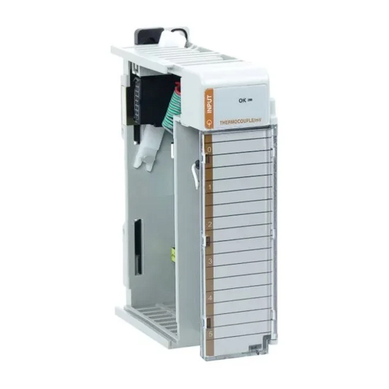
Chapter 1 Overview Data Formats The data can be configured on board each module as: • engineering units x 1. • engineering units x 10. • scaled-for-PID. • percent of full-scale. • raw/proportional data. Filter Frequencies The module uses a digital filter that provides high frequency noise rejection for the input signals. - Page 13 IN 5+ CJC 1- IN 5- CJC 1+ Ensure Adjacent Bus Lever is Unlatched/Latched Before/After Removing/Inserting Module 1769-IT6 Item Description Bus lever Upper-panel mounting tab Lower-panel mounting tab Module status indicator Module door with terminal identification label Movable bus connector (bus interface) with female pins...
-
Page 14: General Diagnostic Features
Chapter 1 Overview General Diagnostic Features The module contains a diagnostic status indicator that helps you identify the source of anomalies that may occur during powerup or during normal channel operation. The status indicator indicates both status and power. Power-up and channel diagnostics are explained in Chapter 5, Diagnostics and Troubleshooting. -
Page 15: Module Operation
Overview Chapter 1 Module Operation When the module receives a differential input from an analog device, the module’s circuitry multiplexes the input into an A/D converter. The converter reads the signal and converts it as required for the type of input. The module also continuously samples the CJC sensors and compensates for temperature changes at the terminal block cold junction, between the thermocouple wire and the input channel. -
Page 16: Module Field Calibration
Chapter 1 Overview Module Field Calibration The module provides autocalibration, which compensates for offset and gain drift of the A/D converter caused by a temperature change within the module. An internal, high-precision, low drift voltage and system ground reference is used for this purpose. -
Page 17: Before You Begin
Quick Start for Experienced Users Before You Begin This chapter can help you to get started using the 1769-IT6 thermocouple/mV input module. We base the procedures here on the assumption that you have an understanding of Allen-Bradley controllers. You should understand electronic process control and be able to interpret the ladder logic instructions required to generate the electronic signals that control your application. - Page 18 ATTENTION: Remove power before removing or inserting this module. If you remove or insert a module with power applied, an electrical arc may occur. To reduce the effects of electrical noise, install the 1769-IT6 module at IMPORTANT least two slots away from Compact I/O 120/240V AC power supplies.
- Page 19 Quick Start for Experienced Users Chapter 2 Be sure the bus lever is locked firmly in place. ATTENTION: When attaching I/O modules, it is very important that the bus connectors are securely locked together to be sure of proper electrical connection. 6.
- Page 20 – For insulated/ungrounded thermocouples, this is at the module end. Contact your sensor manufacturer for additional details. • Refer to Industrial Automation Wiring and Grounding Guidelines, Allen-Bradley publication 1770-4.1, for additional information. Figure 2 - Terminal Connections with CJC Sensors CJC 0+...