
Related Manuals for Seneca Z-8TC-SI


Summary of Contents for Seneca Z-8TC-SI
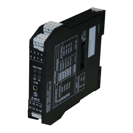
- Page 1 USER MANUAL Z-8TC-SI Z-8TC-SI-LAB 8-CHANNEL 24BIT ADC THERMOCOUPLE CONVERTER SENECA S.r.l. Via Austria 26 – 35127 – Z.I. - PADOVA (PD) - ITALY Tel. +39.049.8705355 – 8705355 Fax +39 049.8706287 www.seneca.it ORIGINAL INSTRUCTIONS...
- Page 2 Set-up must be performed only after correct installation and the user must follow all the operations described in the installation manual carefully. Seneca is not responsible for failures, breakages and accidents caused by ignorance or failure to apply the stated requirements.
- Page 3 User Manual Z-8TC-SI Document revisions DATE REVISION NOTES AUTHOR 12/10/2022 First revision Summary fix 19/12/2022 Modbus Register Fix 20/12/2022 ALL RIGHTS RESERVED. NO PART OF THIS www.seneca.it Page 3 PUBLICATION MAY BE REPRODUCED WITHOUT MI00595-2-EN PRIOR PERMISSION.
-
Page 4: Table Of Contents
User Manual Z-8TC-SI TABLE OF CONTENTS INTRODUCTION ......................6 DESCRIPTION ......................6 TYPE OF SUPPORTED THERMOCOUPLE ..............7 MEASUREMENT OF THE COLD JUNCTION .............. 7 RESPONSE MEASURES AND TIMES ................ 8 SAMPLING TIMES AND MEASUREMENT UPDATE TIME ........8 FILTER ........................8 MODBUS RESPONSE TIME .................. - Page 5 REPRESENTATION OF A 32-BIT VALUE IN TWO CONSECUTIVE MODBUS HOLDING REGISTERS ..................... 14 TYPE OF 32-BIT FLOATING POINT DATA (IEEE 754) ......... 14 Z-8TC-SI: MODBUS 4X HOLDING REGISTERS TABLE (FUNCTION CODE 3) ... 16 ALL RIGHTS RESERVED. NO PART OF THIS www.seneca.it...
-
Page 6: Introduction
Use the installation manual for more information. ATTENTION! In any case, SENECA s.r.l. or its suppliers will not be responsible for the loss of data/revenue or consequential or incidental damages due to negligence or bad/improper management of the device, even if SENECA is well aware of these possible damages. -
Page 7: Type Of Supported Thermocouple
User Manual Z-8TC-SI TYPE OF SUPPORTED THERMOCOUPLE The supported sensors are: MEASURING SENSOR STANDARD RANGE EN 60584-1:1997 -210 ÷ +1200°C EN 60584-1:1997 -200 ÷ +1372°C EN 60584-1:1997 -50 ÷ +1768°C EN 60584-1:1997 -50 ÷ +1768°C EN 60584-1:1997 -200 ÷ +400°C EN 60584-1:1997 +250 ÷... -
Page 8: Response Measures And Times
CHANNEL SPEED: Allows you to set the channel sampling time TERMINAL CONFIGURATION: Allows you to choose the configuration of the measurement terminals according to the Z-8TC-SI or Z-8TC-SI-LAB model. INTERPRETATION OF FLOATING POINTS: Allows you to set whether the single precision (32 bit) Floating Point registers are to be interpreted with the most significant value on the high word or on the low word. -
Page 9: Usb Connection And Configuration Reset
User Manual Z-8TC-SI CHANNEL OFFSET Allows you to set the measurement offset value. USB CONNECTION AND CONFIGURATION RESET The front USB port allows a simple connection to configure the device via the configuration software. If it is necessary to restore the instrument factory configuration, use the configuration software. -
Page 10: Modbus Communication Protocol
User Manual Z-8TC-SI MODBUS COMMUNICATION PROTOCOL The supported communication protocol is: Modbus RTU Slave (from both the RS485 and USB ports) ▪ For more information on these protocols, see the website: http://www.modbus.org/specs.php. SUPPORTED MODBUS FUNCTION CODES The following Modbus functions are supported:... -
Page 11: Modbus Register Table
According to the Modbus standard the Holding Registers are addressable from 0 to 65535, there are 2 different conventions for numbering the addresses: "0-BASED" and "1-BASED". For greater clarity, Seneca shows its register tables in both conventions. ATTENTION! CAREFULLY READ THE DOCUMENTATION OF THE MODBUS MASTER DEVICE IN ORDER TO UNDERSTAND WHICH OF THE TWO CONVENTIONS THE MANUFACTURER HAS DECIDED TO USE NUMBERING OF MODBUS ADDRESSES WITH "0 -BASED"... -
Page 12: Numbering Of Modbus Addresses With "1 Based" Convention
User Manual Z-8TC-SI The numbering is: HOLDING REGISTER MODBUS MEANING ADDRESS (OFFSET) FIRST REGISTER SECOND REGISTER THIRD REGISTER FOURTH REGISTER FIFTH REGISTER Therefore, the first register is at address 0. In the following tables, this convention is indicated with “ADDRESS OFFSET”. -
Page 13: Bit Convention Within A Modbus Holding Register
User Manual Z-8TC-SI BIT CONVENTION WITHIN A MODBUS HOLDING REGISTER A Modbus Holding Register consists of 16 bits with the following convention: For instance, if the value of the register in decimal is 12300 the value 12300 in hexadecimal is:... - Page 14 User Manual Z-8TC-SI REPRESENTATION OF A 32-BIT VALUE IN TWO CONSECUTIVE MODBUS HOLDING REGISTERS The representation of a 32-bit value in the Modbus Holding Registers is made using 2 consecutive Holding Registers (a Holding Register is a 16-bit register). To obtain the 32-bit value it is therefore necessary to read two...
- Page 15 User Manual Z-8TC-SI Using the last representation the value 2.54 is represented at 32 bits as: 0x40228F5C Since we have 16-bit registers available, the value must be divided into MSW and LSW: 0x4022 (16418 decimal) are the 16 most significant bits (MSW) while 0x8F5C (36700 decimal) are the 16 least significant bits (LSW).
- Page 16 User Manual Z-8TC-SI Z-8TC-SI: MODBUS 4X HOLDING REGISTERS TABLE (FUNCTION CODE 3) ADDRESS OFFSET REGISTER ORDER CHANNEL DESCRIPTION TYPE (4x) Device UNSIGNED 40001 MACHINE ID identification 16 BIT Cold Junctions and Burnout Errors ( 0 = OK, 1 = ERROR) Bit[15]=CJ Error IN1&IN2...
- Page 17 User Manual Z-8TC-SI Integer measure INTEGER SIGNED 16 40007 [°C/10] or MEASURE [10*mV] Integer measure INTEGER SIGNED 16 40008 [°C/10] or MEASURE [10*mV] Integer measure INTEGER SIGNED 16 40009 [°C/10] or MEASURE [10*mV] Integer measure INTEGER SIGNED 16 40010 [°C/10] or...
- Page 18 User Manual Z-8TC-SI UNSIGNED 40033 RESERVED 16 BIT UNSIGNED 40034 RESERVED 16 BIT UNSIGNED 40035 RESERVED 16 BIT FIRMWARE UNSIGNED 40036 REVISION 16 BIT FLASH ERRORS ( 0 = OK, 1 = ERROR) Bit[13]= FLASH ERROR IN1&IN2 UNSIGNED 40037 FLASH ERRORS...
- Page 19 User Manual Z-8TC-SI UNSIGNED 40048 RESERVED 16 BIT UNSIGNED 40049 RESERVED 16 BIT UNSIGNED 40050 RESERVED 16 BIT UNSIGNED 40051 RESERVED 16 BIT Bit[15:8] Modbus Address RS485: 0..255 UNSIGNED 40052 ADDRESS_PARITY Bit[7:0] Parity : 16 BIT 0=none 1=even 2=odd Bit[15:8]...
- Page 20 User Manual Z-8TC-SI CHANNEL CONFIGURATION Bit[12:10] Filter: 0=NO, 1=10 elements moving average Bit[9:6] TC TYPE : 0= J 1= K 2= R 3= S 4= T 5= B 6= E 7= N 8= L 9= mV INPUT USER UNSIGNED 40055...
- Page 21 User Manual Z-8TC-SI CHANNEL CONFIGURATION Bit[12:10] Filter: 0=NO, 1=10 elements moving average Bit[9:6] TC TYPE : 0= J 1= K 2= R 3= S 4= T 5= B 6= E 7= N 8= L 9= mV INPUT USER UNSIGNED 40057...
- Page 22 User Manual Z-8TC-SI CHANNEL CONFIGURATION Bit[12:10] Filter: 0=NO, 1=10 elements moving average Bit[9:6] TC TYPE : 0= J 1= K 2= R 3= S 4= T 5= B 6= E 7= N 8= L 9= mV INPUT USER UNSIGNED 40059...
- Page 23 User Manual Z-8TC-SI CHANNEL CONFIGURATION Bit[12:10] Filter: 0=NO, 1=10 elements moving average Bit[9:6] TC TYPE : 0= J 1= K 2= R 3= S 4= T 5= B 6= E 7= N 8= L 9= mV INPUT USER UNSIGNED 40061...
- Page 24 FAULT VALUE [°C/10] OR [mV/100] UNSIGNED 40071 RESERVED 16 BIT THERMOCOUPLES CONNECTION CONNECTION TYPE UNSIGNED 40072 TYPE Bit[0] 16 BIT 0= Z-8TC-SI 1= Z-8TC-SI-LAB UNSIGNED 40073 RESERVED 16 BIT UNSIGNED 40074 RESERVED 16 BIT 40075 RESERVED FLOAT 32 40076 UNSIGNED 40077...
- Page 25 User Manual Z-8TC-SI UNSIGNED 40081 RESERVED 16 BIT 40082 UNSIGNED RESERVED RESERVED 32 BIT 40083 40084 UNSIGNED RESERVED RESERVED 32 BIT 40085 40086 UNSIGNED RESERVED RESERVED 32 BIT 40087 40088 UNSIGNED ADC RAW VALUE RAW ADC VALUE 32 BIT 40089...
- Page 26 User Manual Z-8TC-SI 40123 40124 RESERVED FLOAT 32 40125 40126 RESERVED FLOAT 32 40127 40128 RESERVED FLOAT 32 40129 40130 RESERVED FLOAT 32 40131 40132 RESERVED FLOAT 32 40133 40134 RESERVED FLOAT 32 40135 40136 RESERVED FLOAT 32 40137 40138...