Table of Contents
Quick Links
Service
Manual
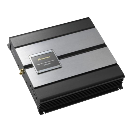
BRIDGEABLE POWER AMPLIFIER
PRS-A500
For details, refer to "Important check points for good servicing".
PIONEER CORPORATION
PIONEER ELECTRONICS (USA) INC.
PIONEER EUROPE NV
Haven 1087 Keetberglaan 1, 9120 Melsele, Belgium
PIONEER ELECTRONICS ASIACENTRE PTE.LTD. 253 Alexandra Road, #04-01, Singapore 159936
C PIONEER CORPORATION 2004
PRS-A500/X1H/EW
4-1, Meguro 1-Chome, Meguro-ku, Tokyo 153-8654, Japan
P.O.Box 1760, Long Beach, CA 90801-1760 U.S.A.
/X1H/EW
K-ZZB. DEC. 2004 Printed in Japan
ORDER NO.
CRT3353
Table of Contents

Related Manuals for Pioneer PRS-A500/X1H/EW


Summary of Contents for Pioneer PRS-A500/X1H/EW
- Page 1 PIONEER ELECTRONICS (USA) INC. P.O.Box 1760, Long Beach, CA 90801-1760 U.S.A. PIONEER EUROPE NV Haven 1087 Keetberglaan 1, 9120 Melsele, Belgium PIONEER ELECTRONICS ASIACENTRE PTE.LTD. 253 Alexandra Road, #04-01, Singapore 159936 C PIONEER CORPORATION 2004 K-ZZB. DEC. 2004 Printed in Japan...
-
Page 2: Safety Information
- Service Precaution You should conform to the regulations governing the product (safety, radio and noise, and other regulations), and should keep the safety during servicing by following the safety instructions described in this manual. PRS-A500/X1H/EW... - Page 3 To protect products from damages or failures during transit, the shipping mode should be set or the shipping screws should be installed before shipment. Please be sure to follow this method especially if it is specified in this manual. PRS-A500/X1H/EW...
-
Page 4: Table Of Contents
2. EXPLODED VIEWS AND PARTS LIST ......6 7. GENERAL INFORMATION........25 2.1 PACKING..............6 7.1 DIAGNOSIS ............25 2.2 EXTERIOR ............8 7.1.1 DISASSEMBLY.........25 3. SCHEMATIC DIAGRAM...........10 7.1.2 ..26 CONNECTOR FUNCTION DESCRIPTION 3.1 SCHEMATIC DIAGRAM (GUIDE PAGE) ...10 8. OPERATIONS ............27 4. PCB CONNECTION DIAGRAM........16 4.1 AMP UNIT............16 PRS-A500/X1H/EW... -
Page 5: Specifications
• Specifications and the design are subject to possible modification without notice due to improvements. *Average current drawn • The average current drawn is nearly the maximum current drawn by this unit when an audio signal is input. Use this value when working out total current drawn by multiple power amplifiers. PRS-A500/X1H/EW... -
Page 6: Exploded Views And Parts List
- Screws adjacent to ∇ mark on the product are used for disassembly. - For the applying amount of lubricants or glue, follow the instructions in this manual. ( In the case of no amount instructions, apply as you think it appropriate.) 2.1 PACKING PRS-A500/X1H/EW... - Page 7 3 Polyethylene Bag HEG0011 4 Contain Box HHL0446 5 Protector HHP0266 6 Carton HHG0446 7 Polyethylene Bag HEG0022 8-1 Owner’s Manual HRD0280 8-2 Warranty Card HRY1157 - Owner's Manual Part No. Language HRD0280 English, Spanish, German, French, Italian, Dutch PRS-A500/X1H/EW...
-
Page 8: Exterior
2.2 EXTERIOR PRS-A500/X1H/EW... - Page 9 HKE0012 25 Terminal(CN851) HKE0021 26 Terminal(CN852) HKE0021 27 Terminal(CN601) HKE1054 28 Terminal(CN604) HKF0001 > 29 Fuse(FU602,603)(20A) HEK0020 30 Screw PPZ30P100SAD 31 Light Pipe HXA0426 32 Screw PPZ30P080FZK 33 Screw PPZ30P120FZK 34 Screw BBZ30P060FZK 35 Badge HAM0036 36 Screw HBA1639 PRS-A500/X1H/EW...
-
Page 10: Schematic Diagram
+39.1V +/- 3V -39.1V +/- 3V +37.1V +/- 3V -37.1V +/- 3V +39.1V +/- 3V -39.1V +/- 3V +37.1V +/- 3V -37.1V +/- 3V > +37.1V > > -37.1V > +39.1V -39.1V > +37.1V > > -37.1V > +39.1V -39.1V PRS-A500/X1H/EW... - Page 11 : Therefore, when replacing, be sure to use parts of ← Symbol indicates a capacitor. identical designation. ← No differentiation is made between chip capacitors and 0.022 R022 discrete capacitors. PRS-A500/X1H/EW...
- Page 12 PRS-A500/X1H/EW...
- Page 13 PRS-A500/X1H/EW...
- Page 14 PRS-A500/X1H/EW...
- Page 15 PRS-A500/X1H/EW...
-
Page 16: Pcb Connection Diagram
1.The parts mounted on this PCB include all necessary parts for several destination. For further information for respective destinations, be sure to check with the schematic dia- gram. 2.Viewpoint of PCB diagrams Capacitor Connector SIDE A LPF/HPF SIDE B P.C.Board Chip Part FREQ PRS-A500/X1H/EW... - Page 17 SIDE A PRS-A500/X1H/EW...
- Page 18 AMP UNIT PRS-A500/X1H/EW...
- Page 19 SIDE B PRS-A500/X1H/EW...
-
Page 20: Electrical Parts List
(A,84,64) Diode HZS9L(A1) (A,115,215) FET 94-4633 (A,84,184) Diode HZS9L(A1) (A,130,103) Transistor 2SC2458 (A,84,51) Diode 1SS133 (A,121,108) Transistor 2SA1048 (A,84,192) Diode 1SS133 (A,162,107) Transistor 2SB1243 (A,269,156) Diode RM4Z-LFJ4 (A,198,135) Transistor 2SA1048 (A,138,103) Diode HZS7L(B2) (A,222,123) Transistor 2SC2458 (A,123,114) Diode ERA15-02VH PRS-A500/X1H/EW... - Page 21 (A,64,61) 100Ω CCN1096 (A,64,182) 100Ω CCN1096 (A,23,59) RD1/4PU103J (A,49,124) RD1/4PU103J (A,87,63) 100Ω CCN1096 (A,40,68) RD1/4PU103J (A,87,180) 100Ω CCN1096 (A,56,125) RD1/4PU103J (A,71,58) RD1/4PU222J (A,37,83) RD1/4PU103J (A,71,185) RD1/4PU222J (A,48,47) 100Ω HCN1141 (A,46,129) RD1/4PU103J (A,51,86) RD1/4PU472J (A,57,134) RD1/4PU472J (A,46,95) RD1/4PU562J (A,54,145) RD1/4PU562J PRS-A500/X1H/EW...
- Page 22 (A,211,123) RD1/4PU331J (A,251,130) RD1/4PU472J (A,278,39) RD1/4PU473J (A,246,109) RD1/4PU472J (A,279,186) RD1/4PU473J (A,246,135) RD1/4PU472J CAPACITORS (A,244,29) RS1/2PMF121J (A,233,214) RS1/2PMF121J (A,40,64) 33pF HCF0004 (A,262,29) RS1/2PMF121J (A,56,122) 33pF HCF0004 (A,251,214) RS1/2PMF121J (A,46,89) CFTNA154J50 (A,230,29) RS1/2PMF121J (A,54,151) CFTNA154J50 (A,219,214) RS1/2PMF121J (A,59,85) CFTNA154J50 (A,212,29) RS1/2PMF121J PRS-A500/X1H/EW...
- Page 23 (A,254,71) 3300µF/16V HCH0005 (A,178,206) CQMA102J50 (A,169,37) CQMA102J50 (A,164,206) CQMA102J50 (A,184,37) CQMA102J50 (A,151,158) 6800µF/50V HCH1550 (A,151,85) 6800µF/50V HCH1550 (A,188,158) 6800µF/50V HCH1550 (A,188,85) 6800µF/50V HCH1550 (A,171,174) CQPA102G2A (A,171,69) CQPA102G2A (A,178,174) CQPA102G2A (A,178,69) CQPA102G2A (A,132,160) CEAT221M50 (A,132,88) CEAT221M50 (A,138,181) CEAT221M50 (A,138,70) CEAT221M50 PRS-A500/X1H/EW...
-
Page 24: Adjustment
1. The idle current should be set when the amplifier has not been in operation for a long time and also should be set when at room temperature. 2. PCB assembly must be mounted in the heatsink and all power transistors must be attached to the heatsink using the proper fastners. PRS-A500/X1H/EW... -
Page 25: General Information
Remove the six screws. Remove the seven screws and then remove the Case. Fig.1 Case Removing the Amp Unit (Fig.2) Remove the sixteen screws. Remove the four screws. Remove the ten screws and then remove the Amp Unit. Amp Unit Fig.2 PRS-A500/X1H/EW... -
Page 26: Connector Function Description
7.1.2 CONNECTOR FUNCTION DESCRIPTION PRS-A500/X1H/EW... -
Page 27: Operations
8. OPERATIONS PRS-A500/X1H/EW...