Honeywell 7800 Series Installation Instructions Manual
Relay modules
Hide thumbs
Also See for 7800 Series:
- Product data (64 pages) ,
- Manual (56 pages) ,
- Installation instructions manual (40 pages)
Table of Contents
Quick Links
APPLICATION
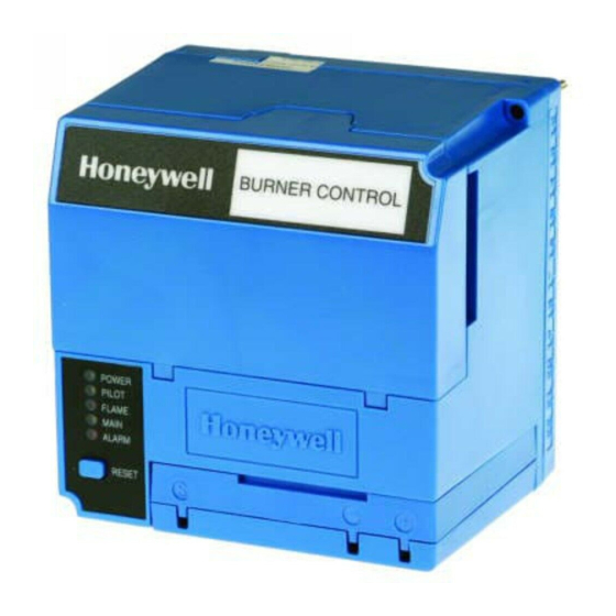
The Honeywell RM7845A Relay Modules are microprocessor-
based integrated burner controls for automatically fired gas,
oil, or combination fuel single burner applications. The Relay
Modules are used for UL/CSA On/Off, UL/CSA Modulating,
and FM/IRI Modulating burner applications. The system
consists of a Relay Module. Keyboard Display Modules, Dust
Cover, Subbase, Amplifier, and Purge Card. Options include
Personal Computer Interface, DATA CONTROLBUS
MODULE™, Remote Display Mounting, First-Out Expanded
Annunciator and Combustion System Manager™ Software.
Functions provided by the relay module include automatic
burner sequencing, flame supervision, system status
indication, system or self-diagnostics and troubleshooting.
The relay module is a solid state device.
This document provides installation and static checkout
instructions. Other applicable publications are:
65-0084:Q7800A,B 22-Terminal Wiring Subbase Product
Data.
65-0089:ST7800A Plug-In Purge Timer Installation
Instructions.
65-0090:S7800A Keyboard Display Module Product Data.
65-0091:S7810A Data ControlBus Module™ Product Data.
65-0095:S7820 Remote Reset Module Product Data.
65-0097:221729C Dust Cover Packing Sheet.
65-0101:S7830 Expanded Annunciator Product Data.
65-0109:R7824, R7847, R7848, R7849, R7851, R7861,
R7886 Flame Amplifiers for the 7800 SERIES Product
Data.
65-0131:221818A Extension Cable Assembly Product
Data.
65-0228:7800 SERIES Multi-Drop Switch Module Product
Data.
65-0229:7800 SERIES RELAY MODULES Checkout and
Troubleshooting Product Data.
65-0249:S7810M ModBus™ Module Product Data.
SPECIFICATIONS
Electrical Ratings, see Table 3:
Voltage and Frequency: 120 Vac (+10/-15%), 50 or 60 Hz
(±10%).
® U.S. Registered Trademark
© 2004 Honeywell International Inc.
All Rights Reserved
7800 SERIES Relay Modules
Power Dissipation: 10W maximum.
Maximum Total Connected Load: 2000 VA.
Fusing: 15A maximum, Type SC or equivalent Fast Blow.
Environmental Ratings:
Ambient Temperature:
Operating: -40°F to +140°F (-40°C to +60°C).
Storage: -40°F to +150°F (-40°C to +66°C).
Humidity: 85% relative humidity continuous, noncondensing.
Vibration: 0.5G environment.
Approvals:
Underwriters Laboratories Inc. Listed: File No. MP268,
Guide No. MCCZ.
Canadian Standards Association Certified: LR9S329-3.
Factory Mutual Approved: Report No. J.I.1V9A0.AF.
IRI Acceptable.
Federal Communications Commission, Part 15,
Class B—Emissions.
INSTALLATION
When Installing this Product...
1. Read these instructions carefully. Failure to follow
them could damage the product or cause a hazardous
condition.
2. Check the ratings given in the instructions and marked
on the product to make sure the product is suitable for
the application.
3. Installer must be a trained, experienced, flame
safeguard service technician.
4. After installation is complete, check out the product
operation as provided in these instructions.
RM7845A
INSTALLATION INSTRUCTIONS
WARNING
Fire or Explosion Hazard.
Can cause property damage, severe injury,
or death.
To prevent possible hazardous burner operation, verify
safety requirements each time a control is installed on
a burner.
66-1147—1
Table of Contents

Related Manuals for Honeywell 7800 Series


Summary of Contents for Honeywell 7800 Series
- Page 1 65-0101:S7830 Expanded Annunciator Product Data. condition. 65-0109:R7824, R7847, R7848, R7849, R7851, R7861, 2. Check the ratings given in the instructions and marked R7886 Flame Amplifiers for the 7800 SERIES Product on the product to make sure the product is suitable for Data. the application.
-
Page 2: Mounting Wiring Subbase
RM7845A 7800 SERIES RELAY MODULES Weather WARNING The relay module is not designed to be weather tight. When installed outdoors, protect the relay module using an Electrical Shock Hazard. approved weather-tight enclosure. Can cause serious injury or death. Disconnect the power supply before beginning installation. -
Page 3: Final Wiring Check
RM7845A 7800 SERIES RELAY MODULES 7. Recommended wire routing of leadwires: c. Remote Reset leadwires—The maximum length of a. Do not run high voltage ignition transformer wires in wire is 1000 feet to a Remote Reset pushbutton. the same conduit with the flame detector, Data d. - Page 4 RM7845A 7800 SERIES RELAY MODULES (HOT) 120 Vac, 50/60 Hz PLUG-IN PURGE CONFIGURATION TIMER CARD JUMPERS TEST FLAME SIGNAL JACK RUN/TEST SWITCH PLUG-IN MICROCOMPUTER FLAME AMPLIFIER TEST RESET PUSHBUTTON RELAY DRIVE RELAY CIRCUIT STATUS FEEDBACK AND LINE VOLTAGE INPUTS SAFETY RELAY...
- Page 5 RM7845A 7800 SERIES RELAY MODULES Table 2. Recommended Grounding Practices. Ground Type Recommended Practice Earth ground (subbase and relay module). 1. Use to provide a connection between the subbase and the control panel of the equipment. Earth ground must be capable of conducting enough current to blow the 20A fuse (or breaker) in the event of an internal short circuit.
- Page 6 RM7845A 7800 SERIES RELAY MODULES Table 4. Combinations for Terminals 8 and 9. Combination No. IGN/Pilot Fuel 8 Main 9 Table 5. Explanation of Each Combination. 4.5A ignition. 50 VA Pilot Duty plus 180 VA ignition plus 2A Pilot Duty.
- Page 7 RM7845A 7800 SERIES RELAY MODULES SERIES 90 FIRING RATE SERIES 90 Q7800 MOTOR CONTROLLER HIGH FIRE COMMON LOW FIRE 120V ALARM MODULATE (L1) BURNER MOTOR (BLOWER) BURNER CONTROLLER/LIMITS LOCKOUT INTERLOCKS LOW FIRE (INC. AIR FLOW SWITCH) START SWITCH 120V, 50/60 Hz POWER SUPPLY. PROVIDE 10 SEC.
-
Page 8: Safety Shutdown
RM7845A 7800 SERIES RELAY MODULES WIRING SUBBASE RUN/TEST SWITCH H O N E Y W E LL RELAY MODULE CONFIGURATION JUMPERS PURGE TIMER SEQUENCE STATUS LED PANEL POWE R RESET PILOT BUTTON FLAM E MAIN ALAR M CAPTIVE RESE T... -
Page 9: Sequence Of Operation
RM7845A 7800 SERIES RELAY MODULES Main valve terminal is energized. and the hold condition exists for four minutes, the RM7845A Internal system fault occurred. locks out. Causes for hold conditions in the INITIATE k. Purge card is removed. sequence: Purge card is bad. -
Page 10: Settings And Adjustments
RM7845A 7800 SERIES RELAY MODULES b. Flame must be proven by the end of the ten-second 3. The RM7845A is now in RUN and remains in RUN until PFEP (four if JR1 is clipped) to allow the sequence the controller input, terminal 6, opens, indicating that the to continue. -
Page 11: Static Checkout
RM7845A 7800 SERIES RELAY MODULES SELECTABLE CONFIGURATION JUMPERS RUN/TEST SWITCH M22634 Fig. 4. Selectable site-configurable jumpers. Table 7. Site Configurable Jumper Options. Jumper Number Description Intact Clipped RM7845A Type Pilot Flame Establishing 10 seconds 4 seconds Period (PFEP) — —... - Page 12 RM7845A 7800 SERIES RELAY MODULES 5. For each test, open the master switch and install the 11. Make sure normal operation is obtained for each jumper wire(s) between the subbase wiring terminals required test before continuing the checkout. listed in the Test Jumpers column.
- Page 13 RM7845A 7800 SERIES RELAY MODULES Table 8. Static Checkout. (Continued) Test RM7845A Test If Operation is Abnormal, Models Jumpers Voltmeter Normal Operation Check the Items Listed Below 15-13 — 1. Raise setpoint of Series 90 1. Series 90 Controller. controller—firing rate motor 2.
- Page 14 66-1147—1...
- Page 15 66-1147—1...
- Page 16 Automation and Control Solutions Honeywell International Inc. Honeywell Limited-Honeywell Limitée 1985 Douglas Drive North 35 Dynamic Drive Golden Valley, MN 55422 Scarborough, Ontario M1V 4Z9 66-1147—1 G.R. Rev. 12-04 www.honeywell.com...