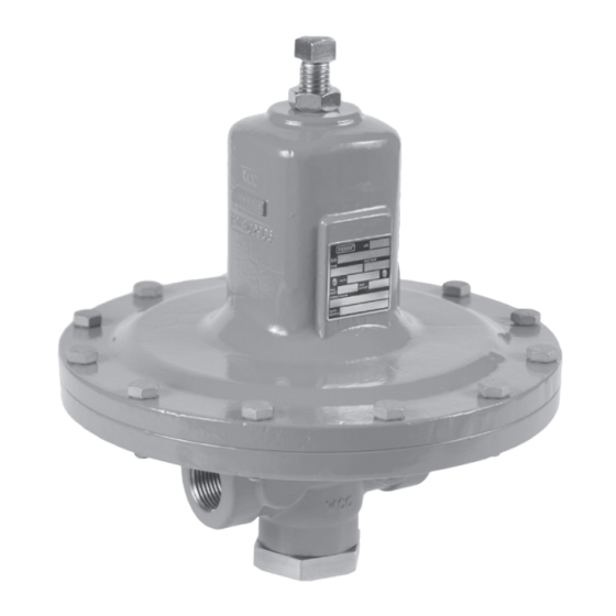
Emerson FISHER MR98 Series Installation Manual
Hide thumbs
Also See for FISHER MR98 Series:
- Instruction manual (36 pages) ,
- Installation manual (6 pages) ,
- Manual (20 pages)
Quick Links
Installation Guide
D103588X014
English – October 2022
Introduction
This Installation Guide provides instructions for
installation, startup and adjustment. To receive a
copy of the instruction manual, contact your local
Sales Office or view a copy at www.fisher.com. For
further information refer to MR98 Series Backpressure
Regulators, Relief and Differential Relief valves
Instruction Manual, D103588X012.
P.E.D. Category
This product may be used as a safety accessory
with pressure equipment in the following Pressure
Equipment Directive. It may also be used outside
of the Pressure Equipment Directive using Sound
Engineering Practice (SEP) per table below. For
information on the current PED revision see Bulletin:
D103053X012. For information on the current PED
revision see Bulletin: D103053X012.
TYPE
PRODUCT SIZE
1/4 NPT, DN 15 to
All
25 / 1/2 to 1 in.
MR98H/MR98HD/
DN 40 and 50 /
MR98HDP
1-1/2 and 2 in.
Specifications
Available Constructions
Type MR98L: Backpressure regulator/relief valve
for spring settings range from 0.14 to 2.6 bar /
2 to 38 psig, available for 1/4 NPT to DN 25 / 1 in.
body sizes only
Type MR98H: Backpressure regulator/relief valve
for spring settings range from 0.34 to 13.8 bar /
5 to 200 psig
Type MR98HH: Backpressure regulator/relief
valve for spring settings range from 10.3 to
25.9 bar / 150 to 375 psig
Type MR98LD: Differential pressure relief valve
for differential set pressures range from 0.14 to
2.6 bar / 2 to 38 psi with maximum inlet/outlet
pressure up to 10.3 bar / 150 psi, available for
1/4 NPT to DN 25 /1 in. body sizes only
1. The pressure/temperature limits in this Installation Guide and any applicable standard or code limitation should not be exceeded.
BODY MATERIAL
CATEGORY
All available
SEP
materials
Steel and
II
Stainless Steel
Available Constructions (continued)
Type MR98HD: Differential pressure relief valve
for differential set pressures from 0.34 to
13.8 bar / 5 to 200 psi with maximum inlet/outlet
pressure up to 20.7 bar / 300 psi
Type MR98HDP: Differential pressure relief valve
for differential set pressures range from 0.34 to
13.8 bar / 5 to 200 psi with maximum inlet/outlet
pressure up to 41.4 bar / 600 psi
Type MR98HHD: Differential pressure relief valve
for differential set pressures range from 10.3 to
25.9 bar / 150 to 375 psi with maximum inlet/outlet
pressure up to 27.6 bar / 400 psi
Body and Orifice Sizes
1/4 NPT body: 7.22 mm / 0.284 in. orifice
DN 15 / 1/2 in. body:
10.56 mm / 0.416 in. orifice
DN 20 and 25 / 3/4 and 1 in. bodies:
16.02 mm / 0.631 in. orifice
DN 40 and 50 / 1-1/2 and 2 in. bodies:
29 mm / 1.142 in. orifice
End Connection Styles
NPT, SWE and Welded and Integral CL150 RF,
CL300 RF and PN 16/25/40 RF; all sizes are
fabricated with slip-on flanges (for welded end
connections) and are EN flanged 356 mm /
14 in. face-to-face
Set Pressure Ranges
(1)
See Table 1
Maximum Cold Working Pressures of Body Size
and Materials
(1)
See Table 2
Maximum Inlet, Outlet and Spring Case
Pressure Ratings
(1)
See Table 2
MR98 Series

Related Manuals for Emerson FISHER MR98 Series


Summary of Contents for Emerson FISHER MR98 Series
- Page 1 Installation Guide MR98 Series D103588X014 English – October 2022 Introduction Available Constructions (continued) Type MR98HD: Differential pressure relief valve This Installation Guide provides instructions for for differential set pressures from 0.34 to installation, startup and adjustment. To receive a 13.8 bar / 5 to 200 psi with maximum inlet/outlet copy of the instruction manual, contact your local pressure up to 20.7 bar / 300 psi Sales Office or view a copy at www.fisher.com.
- Page 2 MR98 Series Specifications (continued) Flow Coefficients Temperature Capabilities of Body Materials (1)(2)(4) BODY SIZE BODY MATERIAL TEMPERATURE RANGE Gray Cast Iron -29 to 208°C / -20 to 406°F - - - - 1/4 NPT 34.3 WCC Steel -29 to 232°C / -20 to 450°F 35.3 LCC Steel -40 to 232°C / -40 to 450°F...
-
Page 3: Maximum Inlet Pressure
To avoid such injury or damage, provide and maintained in accordance with pressure-relieving or pressure-limiting international and applicable codes devices (as required by the appropriate and regulations and Emerson Process code, regulation or standard) to prevent Management Regulator Technologies, service conditions from exceeding limits. Inc. instructions. -
Page 4: Overpressure Protection
MR98 Series Startup Note It is important that the relief valve or The relief valve or backpressure regulator is factory backpressure regulator be installed set at approximately the midpoint of the spring range so that the vent hole in the spring or the pressure requested, so an initial adjustment case is unobstructed at all times. - Page 5 MR98 Series TEE-HANDLE COMPOSITE SEAT CONTROL LINE OPTION OPTION OPTION GF04917 APPLY T = THREAD LOCKER L1 = GENERAL PURPOSE PTFE OR LITHIUM GREASE FOR O-RINGS L2 = ANTI-SEIZE COMPOUND L4 = GRAPHITE SEALANT FOR GRAPHITE RING 1. Lubricants and sealants must be selected such that they meet the temperature requirements. 2.
- Page 6 Technologies, Inc. All rights reserved. 10/22. McKinney, Texas 75070 USA Singapore 128461, Singapore The Emerson logo is a trademark and service mark of Emerson T +1 800 558 5853 T +65 6777 8211 Electric Co. All other marks are the property of their prospective owners.