
Related Manuals for Sony HDC5500


Summary of Contents for Sony HDC5500
- Page 1 4-745-630-13 (1) Color Camera Operating Instructions Before operating the unit, please read this manual thoroughly and retain it for future reference. HDC5500 HDC3500 © 2018 Sony Corporation...
-
Page 2: Table Of Contents
Precautions ..............94 Digital Triax Transmission (when HKC-TR37 is installed)..............94 Error Messages ............. 95 Using a USB Drive..........96 Specifications ............. 97 HDC5500............... 97 HDC3500 ............... 98 HKC-FB50 ..............99 HKC-FB30 ..............99 HKC-TR37 ..............99 HKC-CN50 ..............99 HKC-WL50.............. -
Page 3: Overview
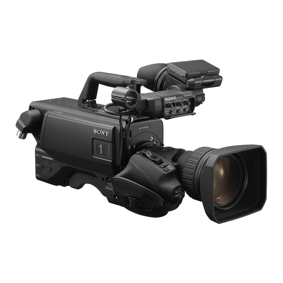
Overview The HDC5500/3500 is a color camera equipped with a newly developed 2/3 inch 4K CMOS sensor with global shutter for F10 (4K/59.94P)/F11 (4K/50P) high sensitivity and high signal-to-noise ratio. Operation as a studio camera is supported when connected with a Camera Control Unit (CCU) using fiber cables. - Page 4 *4Use on triax model is not supported. *5 For the HDC3500, attachment of optional items to the camera control unit is required. For details, contact a Sony sales representative. • Limited subscription licenses are available for each software, with the period of validity of the license indicated by the last character of the name.
-
Page 5: System Configuration
System Configuration Note Production of some of the peripherals and related devices shown in the figures has been discontinued. For advice on choosing devices, please contact your Sony dealer or a Sony sales representative. Connection example (4K optical fiber transmission) HDVF-EL75/L750/L770... - Page 6 Connection example (HD optical fiber transmission) HDVF-EL75/L750/L770 Viewfinder Sync signal input Return video input HDVF-EL20 2K video HDVF-EL30 monitor Intercom Viewfinder microphone CCA-5 input Lens HDC3500 (for ENG/EFP) RCP-3000/1000 series Optical fiber cable Remote Control Panel USB drive d) e) HDCU3100 , HDCU3170 Camera Control Unit...
- Page 7 Connection example (digital triax transmission) HDVF-EL75/L750/L770 Viewfinder HDVF-EL20 HDVF-EL30 Viewfinder HDC3500 Lens (for ENG/EFP) Sync signal input Triax cable Return video input USB drive 2K video Intercom CAC-6 Return Video monitor microphone VCT-14 Tripod Selector input Attachment CCA-5 Intercom headset RCP-3000/1000 series CAC-12 Tripod...
-
Page 8: Locations And Functions Of Parts
Locations and Functions of Parts k Tripod mount Accessory Attachments Attach the VCT-14 Tripod Attachment when mounting the camera on a tripod. l LED lamp Use as a tally. You can switch the function using the menu. m Camera number The unit uses electronic paper (e-ink) type camera numbers. -
Page 9: Controls And Connectors
g GAIN switch Controls and Connectors To select the gain of the video amplifier based on lighting conditions when the camera is used in standalone status without connecting a camera control unit. Front right When shipped from the factory, the values set are L = 0 dB, M = 6 dB, and H = 12 dB. - Page 10 SDI 1 (serial digital interface 1) connector (BNC-type) ON: The electronic shutter is activated. HDC5500: For HD-SDI signal, 3G-SDI signal, 6G-SDI signal, 12G-SDI signal, and UHD PROMPTER signal output. SEL: The shutter speed and shutter mode change each time the switch is set to this position.
- Page 11 INTERCOM 1 and INTERCOM 2 controls and switches There are separate PGM1 and PGM2 controls, line select/ HDC5500: For HD-SDI signal, 3G-SDI signal, 6G-SDI signal, receive MIX select switch, LEVEL/MIC switch, and INCOM and 12G-SDI signal output. Also for HD TRUNK signal level control for both intercom line 1 and intercom line 2.
- Page 12 CE model: TRACKER control For Europe and South Asia Adjust the intercom audio listening level at the TRACKER page 13 connector ( ) on the connector panel when using the connector for intercom. LEVEL switch REAR: The intercom audio listening level is adjusted with the controls on this panel.
-
Page 13: Transmission Adaptor Options
PROMPTER: For output of the prompter 1 signal (valid only Note when a camera control unit is connected). When a To supply +12 V power, contact a Sony sales representative camera control unit having two prompter inputs is or Sony service representative. -
Page 14: Preparations
Connect the lens cable to the LENS connector. HKC-WL50 Wireless Transmission Adaptor Secure the lens cable with the cable clamp. Connects video signals and control signals to a third-party wireless module to support wireless transmission. For details about supported wireless modules, contact your Sony sales representative. -
Page 15: Adjusting The Flange Focal Length
Attaching a viewfinder Adjusting the Flange Focal Length This section describes using a HDVF-20A/200/EL20/EL30 (the HDVF-EL30 is shown in the diagrams). Adjustment of the flange focal length (the distance between the lens mount attachment plane and the imaging For details about the viewfinder, refer to the operation plane) is necessary in the following situations: manual of the viewfinder. -
Page 16: Attaching An Electronic Viewfinder
To adjust the position forward or backward Attach the V-wedge shoe attachment to the camera using the supplied hexagonal wrench and four hexagonal screws (4×12). Viewfinder front-rear positioning lever Set the viewfinder front-rear positioning lever to the unlocked position. Insert the viewfinder firmly into the V-wedge shoe Slide the viewfinder towards the front or rear of the attachment. -
Page 17: Attaching The Cable Clamp Belt (Supplied)
If the tilt/pan angle available for the Attaching the Cable Clamp Belt viewfinder is restricted (Supplied) You can alleviate interference by rotating the camera handle. You can secure the optical/electrical multi cable or triax cable, connected to the CCU connector, to the side of the Loosen the handle rotation lock knob 1 of the camera by attaching the supplied cable clamp belt. -
Page 18: Adjusting The Shoulder Pad Position
1 Release the buckle, 2 bundle the cable with the Adjusting the Shoulder Pad Position belt, 3 then lock the buckle again. You can shift the shoulder pad from its center position (factory setting) backward by up to 10 mm (3/8 inch) or forward by up to 25 mm (1 inch). - Page 19 If the pin of the tripod attachment does not return Mounting procedure to its original position Attach the tripod attachment to the tripod and After removing the camera, if the pin of the tripod secure it with the screw. attachment does not return to its original position, hold down the red button and move the lever in the direction of Tripod attachment the arrow to return the pin to its original position.
-
Page 20: Adjustments And Settings For Shooting
During adjustment, a message like the one in the figure Adjustments and below will be displayed on the viewfinder screen. Settings for Shooting ABB:EXECUTING Adjusting the Black Balance and White Balance In order to maintain high picture quality, it is necessary to When the adjustment process is completed, the message set the black balance and white balance appropriately for “ABB: OK”... - Page 21 Push the AUTO W/B BAL switch to WHT (up). AUTO W/B BAL switch White balance automatic adjustment begins. CC filter select During adjustment, the message “AWB: EXECUTING” will be button displayed on the viewfinder screen. A message like the one in the figure below will be ND filter select displayed, and the adjustment process will complete.
-
Page 22: Setting The Electronic Shutter
• Latency: 1 second or lower (one way) • Bandwidth: 100 kbps or higher Connectors used for simple protocol communication Use one of the following connectors on the HDC5500/3500. • REMOTE connector on the connector panel (supports RS-422A only) SHUTTER switch •... -
Page 23: Setting The Focus Assist Functions
can adjust the signal level (strength) in the range of 0 to Setting the Focus Assist Functions 100% (default 25%). You can adjust the characteristics of the detail signal Using the OPERATION menu, the assist functions for easier with the menu items below. focusing on the viewfinder, can be activated. -
Page 24: Setting The Focus Position Meter Function
See “Adjusting the Flange Focal Length” on page 15 for Thepage is displayed. the flange focal length. 08 TOP INDICATOR : OFF Setting the Focus Position Meter MODE : BOX BOTTOM LEVEL QUICK Function GAIN : 50 OFFSET : 50... -
Page 25: Setting The Vf Dynamic Contrast Function
DIRECTION: Selects whether to display the meter Turn on the camera. horizontally at the top of the screen or vertically on the right edge of the screen. Set the DISPLAY switch to MENU while holding the MENU SELECT knob pressed. SIZE: Sets the size of the meter. -
Page 26: Setting The Camera Outputs
Turn the MENU SELECT knob to display the desired Setting the Camera setting and press the MENU SELECT switch. Outputs To finish the adjustment, set the DISPLAY switch to OFF to exit Menu mode. You can specify video signals directly output from the camera, with menu operations. -
Page 27
Setting
OUTPUT DOWN CONVERTER SELECT Outputting 3G/6G/12G-SDI (HDC5500) The SDI 1 output and SDI 2 output form 3G/6G/12G-SDI output. For details, see “SDI output format with master frequency of 1/1.001” (page 64) and “SDI output format with master frequency of 1/1.000”... -
Page 28: Viewfinder Screen Status Display
Note Viewfinder Screen Status Displayed only when a serial communication lens is connected. Display j Battery voltage Displays the input voltage. Besides the video image, the viewfinder can display text k Marker name of the focus position meter and messages showing the camera settings and operation Displays the marker name of the focus position meter. -
Page 29: Menu Operations
To disable the “TOP” indication Menu Operations Turn the power once off then on again, or set the DISPLAY switch from OFF to MENU while holding the STATUS/ CANCEL switch pressed toward CANCEL. This disables the TOP selection. The menus displayed on the viewfinder screen enable various settings of the camera. -
Page 30: Selecting Pages
To return to the TOP MENU screen Selecting Pages Align the arrow marker ( ) with “TOP” at the top right of the menu page then press the MENU SEL knob/ENTER When selecting a page from a CONTENTS button. page... -
Page 31: Editing The User Menu
For the items on each page, see the corresponding source Set the cursor to the character to be entered and menu page in the table in “Menu List” on page 34. push on the MENU SEL knob/ENTER button. Repeat steps 1 and 2. The USER MENU CUSTOMIZE menu allows you to configure a USER menu that consists only of pages and items that you By selecting INS on the line below the character list, you... - Page 32 Turn the MENU SEL knob/ENTER button to move the EDIT FUNCTION arrow marker ( ) to the position where you wish to INSERT move the item then push on the MENU SEL knob/ MOVE ENTER button. DELETE BLANK ITEM MOVE VF OUT : COLOR VF DETAIL...
- Page 33 To move a page Turn the MENU SEL knob/ENTER button to move the arrow marker ( ) to where you wish to add the Proceed as follows: page, then push on the MENU SEL knob/ENTER button. Display the EDIT PAGE screen of the USER MENU The EDIT FUNCTION screen appears.
-
Page 34: Menu List
Menu List This section shows the menus to be displayed on the Notes viewfinder screen in tables. HDLA: HDLA1500-series Large Lens Adaptor, HDLA1507 • For the pages that have been registered in the USER Large Viewfinder Adaptor menu at the factory, the USER menu page numbers are CCU: HDCU5000/5500/3100/3170/3500/2000/2500 indicated in parenthesis in the No. - Page 35 HEADSET MIC INTERCOM1 CURSOR CURSOR 20 (U11) LEVEL 10 (U07) LEVEL POWER BOX/CROSS UNBAL H POSITION INTERCOM2 V POSITION LEVEL WIDTH POWER HEIGHT UNBAL BOX MEMORY EARPHONE H POSI LEVEL V POSI INTERCOM1 RECEIVE SELECT WIDTH INTERCOM HEIGHT PGM1 VF DYNAMIC CONTRAST DYNAMIC CONTRAST PGM2 GAIN...
- Page 36 PAINT menu DETAIL 2 H/V RATIO SW STATUS FLARE FREQ GAMMA MIX RATIO BLK GAM KNEE APT KNEE DTL H/V MODE WHT CLIP INDEPENDENT DETAIL LVL DEP HD DETAIL DETAIL SKIN DTL LEVEL MATRIX LIMITER M VIDEO LEVEL WHITE LIMITER WHT BLACK LIMITER BLK FLARE...
- Page 37 MAINTENANCE menu FLICKER REDUCTION REDUCTION AUTO SETUP AUTO BLACK POWER LINE FREQUENCY AUTO WHITE MODE AUTO LEVEL GAIN TEST OFFSET WHITE SHADING V SAW ACM TYPE V PARA HDR OPERATION HDR MODE H SAW SDR GAIN H PARA HDR CONTRAST WHITE HDR BLACK OFFSET BLACK SHADING...
- Page 38 FILE menu CALL/TALLY CCU CALL READ (USB t CAM) OPERATOR FILE CAM CALL WRITE (CAM t USB) HDLA UP TALLY PRESET TALLY BRIGHTNESS TORE PRESET FILE NUMBER BRIGHTNESS CLEAR PRESET FILE NUMBER DISPLAY SCENE FILE OUTSIDE LED MODE BRIGHTNESS TALLY GUARD EXTENDER STORE FILTER DISC...
- Page 39 DIAGNOSIS menu When the HKC-TR37 is installed CCU t CAM OPTICAL LEVEL t CCU REFLECTION CABLE LENGTH BOARD STATUS HOURS METER ROM VERSION CAMERA APP D03 (U15) UPDATER PANEL SERIAL NO. MODEL EFFECTIVE FUNCTION POWER SUPPLY STATUS CABLE LENGTH CABLE MARGIN CAM INPUT VOLTAGE CAM CONSUMPTION...
-
Page 40: Operation Menu
OPERATION Menu OPERATION Page name Item Settings Description Page No.ON, OFF, 3S 01 (U04) ZOOM ON, OFF, 3S DISP LEFT, RIGT FORM 999, mm FOCUS ON, OFF, 3S Valid only when a serial lens is used. FORM 999, m, ft ON, OFF, 3S ON, OFF, 3S... -
Page 41
OPERATION Page name Item Settings Description Page No.
MARKER ON, OFF Sets the display of all markers on/off. 03 (U06) WHITE, BLACK, DOT LEVEL MIN, 1 to 10, 4 CENTER ON, OFF 1, 2, 3, 4 1: Full cross 2: Full cross with a hole 3: Center 4: Center with a hole... -
Page 42
OPERATION Page name Item Settings Description Page No.
NEAR LIMIT 0 to 999 Sets the NEAR edge of the focus position meter. FAR LIMIT 0 to 999 Sets the FAR edge of the focus position meter. -
Page 43
OPERATION Page name Item Settings Description Page No.
ZEBRA ON, OFF 09 (U08) 1, 2, 1&2 ZEBRA1 LEVEL 50 to 109%, 70% WIDTH 0 to 30%, 10% ZEBRA2 50 to 109%, 100% CURSOR ON, OFF Displayed only if HDLA attached. 10 (U07) LEVEL WHITE, BLACK, DOT... -
Page 44
OPERATION Page name Item Settings Description Page No.
VF OUT COLOR, Y, R, G, B, Settings in ( ): When HDLA is attached (cannot be changed) 14 (U01) (COLOR), (Y), (R), (G), (B), (RET), (R+G), (R+B), (G+B) CHARACTER LEVEL 1 to 5, 4 PinP OFF, RETURN, HD PROMPTER... -
Page 45
OPERATION Page name Item Settings Description Page No.
VF ASSIGN OFF, RETURN1 SW, RETURN2 Displayed only when HDLA is attached. SW, RETURN3 SW, INCOM1, 15 (U09) INCOM2, EXTENDER, Note D.EXTENDER, 5600K, VF DETAIL, INCOM1 and INCOM2 are displayed on the UCJ page 53 *1: See SPIRIT LEVEL INDICATOR, FOCUS... -
Page 46
OPERATION Page name Item Settings Description Page No.
LENS VTR S/S OFF, RETURN1 SW, RETURN2 Assigns a function to the VTR START/STOP switch SW, RETURN3 SW, INCOM1, on the mounted lens. 16 (U10) INCOM2, EXTENDER, D.EXTENDER, 5600K, VF DETAIL, Note page 53 *1: See... -
Page 47
OPERATION Page name Item Settings Description Page No.
RETURN1 CAM SW TOGGLE, ASSIGNABLE buttons A, B, and C. B PUSH RETURN2 CAM SW, RETURN2 C PUSH CAM SW TOGGLE, RETURN3 Default values:... -
Page 48
OPERATION Page name Item Settings Description Page No.
RET CTRL CONNECTOR RET1 Pin5: OFF, RETURN1 SW, RETURN2 This function works when each pin of the RET CTRL SW, RETURN3 SW, INCOM1, connector contacts with GND (pin 3). INCOM2, EXTENDER, TALLY R, TALLY G, TALLY Y are available only when page 53 *1: See... -
Page 49
OPERATION Page name Item Settings Description Page No.
RET1 SW SEL CCU RET1, CCU RET2, The settings that are available increase according to CCU RET3, CCU RET4 the connected CCU units. RET2 SW SEL RET3 SW SEL RET1 SW + RET2 SW RET1 SW, RET3 SW Changes operation when you press both the RET1 button and RET2 button at the same time. -
Page 50
OPERATION Page name Item Settings Description Page No.
RECEIVE SELECT SEPARATE, MIX Sets the headset audio. SEPARATE: Set L and R separately. MIX: Set L and R to the same settings. INTERCOM ---, LEFT, RIGHT, BOTH UCJ model only When the Line select / Receive MIX select switch on the operation panel is set to MIX, menu items ENG and PROD appear instead of this item (the setting... -
Page 51
OPERATION Page name Item Settings Description Page No.
RECEIVE SELECT SEPARATE, MIX Sets the headset audio. SEPARATE: Set L and R separately. MIX: Set L and R to the same settings. INTERCOM ---, LEFT, RIGHT, BOTH UCJ model only When the Line select / Receive MIX select switch on the operation panel is set to MIX, menu items ENG and PROD appear instead of this item (the setting... -
Page 52
OPERATION Page name Item Settings Description Page No.
RECEIVE SELECT SEPARATE, MIX Sets the headset audio. SEPARATE: Set L and R separately. MIX: Set L and R to the same settings. [1-LR] INTERCOM ---, LEFT, RIGHT, BOTH UCJ model only When the INTERCOM1 Line select / Receive MIX select switch on the operation panel is set to MIX, menu items ENG and PROD appear instead of this... -
Page 53
OPERATION Page name Item Settings Description Page No.
RECEIVE SELECT SEPARATE, MIX Sets the headset audio. SEPARATE: Set L and R separately. MIX: Set L and R to the same settings. INTERCOM ---, LEFT, RIGHT, BOTH UCJ model only When the intercom Line select / Receive MIX select switch selected by OPERATION LINK on the operation panel is set to MIX, menu items ENG and... -
Page 54: Paint Menu
PAINT Menu PAINT Page name Item Settings Description Page No.FLARE ON, OFF GAMMA ON, OFF BLK GAM ON, OFF KNEE ON, OFF WHT CLIP ON, OFF DETAIL ON, OFF LVL DEP ON, OFF SKIN DTL ON, OFF MATRIX ON, OFF -
Page 55
PAINT Page name Item Settings Description Page No.
SATURATION –99 to +99, 0 ON, OFF LOW KEY SAT –99 to +99, 0 RANGE LOW, L.MID, H.MID, HIGH ON, OFF TEST OFF, SAW, 10STEP K POINT R/G/B/M: –99 to +99, 0 R, G, B, and M (master) values can be independently set. -
Page 56
PAINT Page name Item Settings Description Page No.
DETAIL ON, OFF LEVEL –99 to +99, 0 Absolute value is displayed in ABS mode. LIMITER [M] –99 to +99, 0 LIMITER [WHT] –99 to +99, 0 Absolute value is displayed in ABS mode. LIMITER [BLK] –99 to +99, 0 Absolute value is displayed in ABS mode. -
Page 57
PAINT Page name Item Settings Description Page No.
–99 to +99, 0 –99 to +99, 0 –99 to +99, 0 –99 to +99, 0 –99 to +99, 0 –99 to +99, 0 MATRIX ON, OFF PRESET ---, ON, OFF ---, SMPTE-240M, ITU-709, SMPTE-WIDE, NTSC, EBU, ITU-601, CUSTOM1, CUSTOM2,... -
Page 58
PAINT Page name Item Settings Description Page No.
SHUTTER ON, OFF, (ON), (OFF) Settings in ( ): When a remote control unit/panel or a CCU is not connected (cannot be changed) 59.94i: 1/100, 1/125, 1/250, Step shutter selection 1/500, 1/1000, 1/2000 50i: 1/60, 1/125, 1/250, 1/500, 1/1000, 1/2000 29.97PsF: 1/40, 1/60, 1/100,... -
Page 59
PAINT Page name Item Settings Description Page No.
HDR MODE OFF, LIVE HDR Displays the CCU setting. SDR GAIN 0.0 to –15 dB, –6.0 dB Enabled only when LIVE HDR is selected. Gain setting applied to the SDR output. HDR CONTRAST 100 to 566%, 200% Enabled only when LIVE HDR is selected. -
Page 60: Maintenance Menu
MAINTENANCE Menu MAINTENANCE Page name Item Settings Description Page No.AUTO BLACK Execute using ENTER. AUTO WHITE Execute using ENTER. AUTO LEVEL Execute using ENTER. TEST OFF, SAW, 10STEP V SAW R/G/B: –99 to +99, 0 R, G, and B values can be independently set. -
Page 61
MAINTENANCE Page name Item Settings Description Page No.
F NO. DISP CONTROL, RETURN Selects the iris indication on the panel when AUTO IRIS is off: CONTROL: Displays the value from the camera. RETURN: Displays the value returned from the lens. (When AUTO IRIS is on, the value returned from the lens is always displayed.) AF DISPLAY... -
Page 62
MAINTENANCE Page name Item Settings Description Page No.
CAMERA NUMBER ---, 1 to 96 Sets the camera number. CCU LINK OFF, ON Turns the link with the CCU No. on/off. When on, you can set the camera number from the CCU. -
Page 63
MAINTENANCE Page name Item Settings Description Page No.
OUTPUT Display only Displays the current format. M12 (U13) VBS-OUT Displayed when OUTPUT is set to VBS. CHARACTER ON, OFF GAIN –99 to +99, 0 CHROMA –99 to +99, 0 SETUP OFF, ON DOWN CONVERTER... -
Page 64
The following table shows the SDI output formats when the master frequency is 1/1.001. The SDI output format will vary depending on the combination of camera model, transmission adaptor, and camera operating software. 1. Using HDC5500 or HDC3500 with HKC-CN50 and HKC-FB50 installed
SYSTEM FORMAT... -
Page 65
SYSTEM FORMAT HDR/ OUTPUT FORMAT SDI-1 SDI-2 RESOLUTION FREQUENCY OETF Settings Output formats Settings Output formats 1920×1080 29.97PsF S-Log3 – – HD/1.5G/HDR 1920×1080/29.97PsF HD/1.5G/HDR 1920×1080/29.97PsF HD/1.5G/SDR 1920×1080/29.97PsF HD/1.5G/SDR 1920×1080/29.97PsF *1 *2 UHD PROMPTER – UHD TRUNK(12G) IN –... -
Page 66
SYSTEM FORMAT HDR/ OUTPUT FORMAT SDI-1 SDI-2 RESOLUTION FREQUENCY OETF Settings Output formats Settings Output formats 1920×1080 59.94P(2×) S-Log3 – – HD/12G/HDR/HFR 1920×1080/59.94P/Link A-B HD/12G/HDR/HFR 1920×1080/59.94P/Link A-B HD/3G-A/HDR/HFR 1920×1080/59.94P/Link A HD/3G-A/HDR/HFR 1920×1080/59.94P/Link B HD/3G-B/HDR/HFR 1920×1080/59.94P/Link A HD/3G-B/HDR/HFR 1920×1080/59.94P/Link B HD/3G-A/SDR... - Page 67 SYSTEM FORMAT HDR/ OUTPUT FORMAT SDI-1 SDI-2 RESOLUTION FREQUENCY OETF Settings Output formats Settings Output formats 1920×1080 59.94P(4×) S-Log3 – – HD/12G/HDR/HFR 1920×1080/59.94P/Link A-D HD/12G/HDR/HFR 1920×1080/59.94P/Link A-D HD/3G-A/SDR 1920×1080/59.94P HD/3G-A/SDR 1920×1080/59.94P HD/3G-B/SDR 1920×1080/59.94P HD/3G-B/SDR 1920×1080/59.94P HD/1.5G/SDR 1920×1080/59.94i HD/1.5G/SDR 1920×1080/59.94i *1 *2 UHD PROMPTER –...
-
Page 68
SYSTEM FORMAT HDR/ OUTPUT FORMAT SDI-1 SDI-2 RESOLUTION FREQUENCY OETF Settings Output formats Settings Output formats 1920×1080 59.94P(2×) S-Log3 – – HD/12G/HDR/HFR 1920×1080/59.94P/Link A-B HD/12G/HDR/HFR 1920×1080/59.94P/Link A-B HD/3G-A/HDR/HFR 1920×1080/59.94P/Link A HD/3G-A/HDR/HFR 1920×1080/59.94P/Link B HD/3G-B/HDR/HFR 1920×1080/59.94P/Link A HD/3G-B/HDR/HFR 1920×1080/59.94P/Link B HD/3G-A/SDR... -
Page 69
SYSTEM FORMAT HDR/ OUTPUT FORMAT SDI-1 SDI-2 RESOLUTION FREQUENCY OETF Settings Output formats Settings Output formats 1920×1080 59.94i(444) – – (fixed) HD/3G-B/SDR 1920×1080/59.94i(444) HD/3G-B/SDR 1920×1080/59.94i(444) *1 *2 UHD PROMPTER – UHD TRUNK(12G) IN – *1 *2 UHD TRUNK(6G) IN –... -
Page 70
SYSTEM FORMAT HDR/ OUTPUT FORMAT SDI-1 SDI-2 RESOLUTION FREQUENCY OETF Settings Output formats Settings Output formats 3840×2160 59.94P S-Log3 – – 4K/12G/HDR 3840×2160/59.94P 4K/12G/HDR 3840×2160/59.94P HD/3G-A/SDR 1920×1080/59.94P HD/3G-A/SDR 1920×1080/59.94P HD/3G-B/SDR 1920×1080/59.94P HD/3G-B/SDR 1920×1080/59.94P HD/1.5G/SDR 1920×1080/59.94i HD/1.5G/SDR 1920×1080/59.94i *1 *2 UHD PROMPTER... - Page 71 SYSTEM FORMAT HDR/ OUTPUT FORMAT SDI-1 SDI-2 RESOLUTION FREQUENCY OETF Settings Output formats Settings Output formats 3840×2160 59.94P(2×) S-Log3 – – (HZC-HFR50 is 4K/12G/HDR/HFR 3840×2160/59.94P/Link A 4K/12G/HDR/HFR 3840×2160/59.94P/Link B required) 4K/12G/HDR 3840×2160/59.94P 4K/12G/HDR 3840×2160/59.94P HD/3G-A/SDR 1920×1080/59.94P HD/3G-A/SDR 1920×1080/59.94P HD/3G-B/SDR 1920×1080/59.94P HD/3G-B/SDR 1920×1080/59.94P HD/1.5G/SDR...
-
Page 72
SYSTEM FORMAT HDR/ OUTPUT FORMAT SDI-1 SDI-2 RESOLUTION FREQUENCY OETF Settings Output formats Settings Output formats 1920×1080 29.97PsF – – (fixed) HD/1.5G/SDR 1920×1080/29.97PsF HD/1.5G/SDR 1920×1080/29.97PsF HD PROMPTER – HD TRUNK IN – RET IN – 23.98PsF –... -
Page 73
SYSTEM FORMAT HDR/ OUTPUT FORMAT SDI-1 SDI-2 RESOLUTION FREQUENCY OETF Settings Output formats Settings Output formats 1920×1080 59.94i(2×) – – (fixed) HD/3G-B/SDR/HFR(i) 1920×1080/59.94i/Link A-B HD/3G-B/SDR/HFR(i) 1920×1080/59.94i/Link A-B HD PROMPTER – HD TRUNK IN – RET IN –... -
Page 74
SYSTEM FORMAT HDR/ OUTPUT FORMAT SDI-1 SDI-2 RESOLUTION FREQUENCY OETF Settings Output formats Settings Output formats 1920×1080 59.94P S-Log3 – – HD/3G-A/HDR 1920×1080/59.94P HD/3G-A/HDR 1920×1080/59.94P HD/3G-B/HDR 1920×1080/59.94P HD/3G-B/HDR 1920×1080/59.94P HD PROMPTER – RET IN – – –... -
Page 75
3. Using HDC3500 with HKC-CN50 and HKC-TR37 installed for digital triax transmission (equivalent to HDC3170)
SYSTEM FORMAT HDR/ OUTPUT FORMAT SDI-1 RESOLUTION FREQUENCY OETF Settings Output formats 1920×1080 59.94P S-Log3 – HD/3G-A/HDR 1920×1080/59.94P HD/3G-B/HDR 1920×1080/59.94P – HD/3G-A/SDR 1920×1080/59.94P HD/3G-B/SDR 1920×1080/59.94P 59.94P(4K/HDR) -
Page 76
SYSTEM FORMAT HDR/ OUTPUT FORMAT SDI-1 SDI-2 RESOLUTION FREQUENCY OETF Settings Output formats Settings Output formats 1920×1080 59.94P S-Log3 HD/3G-B/HDR 1920×1080/59.94P – HD RETURN IN – HD/3G-B/SDR 1920×1080/59.94P – HD/3G-B/SDR 1920×1080/59.94P HD RETURN IN – SYSTEM FORMAT HDR/ OUTPUT FORMAT... -
Page 77
The following table shows the SDI output formats when the master frequency is 1/1.000. The SDI output format will vary depending on the combination of camera model, transmission adaptor, and camera operating software. 1. Using HDC5500 or HDC3500 with HKC-CN50 and HKC-FB50 installed
SYSTEM FORMAT... -
Page 78
SYSTEM FORMAT HDR/ OUTPUT FORMAT SDI-1 SDI-2 RESOLUTION FREQUENCY OETF Settings Output formats Settings Output formats 1920×1080 25PsF S-Log3 – – HD/1.5G/HDR 1920×1080/25PsF HD/1.5G/HDR 1920×1080/25PsF HD/1.5G/SDR 1920×1080/25PsF HD/1.5G/SDR 1920×1080/25PsF *1 *2 UHD PROMPTER – UHD TRUNK(12G) IN –... -
Page 79
SYSTEM FORMAT HDR/ OUTPUT FORMAT SDI-1 SDI-2 RESOLUTION FREQUENCY OETF Settings Output formats Settings Output formats 1920×1080 50P(2x) S-Log3 – – HD/12G/HDR/HFR 1920×1080/50P/Link A-B HD/12G/HDR/HFR 1920×1080/50P/Link A-B HD/3G-A/HDR/HFR 1920×1080/50P/Link A HD/3G-A/HDR/HFR 1920×1080/50P/Link B HD/3G-B/HDR/HFR 1920×1080/50P/Link A HD/3G-B/HDR/HFR 1920×1080/50P/Link B HD/3G-A/SDR... - Page 80 SYSTEM FORMAT HDR/ OUTPUT FORMAT SDI-1 SDI-2 RESOLUTION FREQUENCY OETF Settings Output formats Settings Output formats 1920×1080 50P(4x) S-Log3 – – HD/12G/HDR/HFR 1920×1080/50P/Link A-D HD/12G/HDR/HFR 1920×1080/50P/Link A-D HD/3G-A/SDR 1920×1080/50P HD/3G-A/SDR 1920×1080/50P HD/3G-B/SDR 1920×1080/50P HD/3G-B/SDR 1920×1080/50P HD/1.5G/SDR 1920×1080/50i HD/1.5G/SDR 1920×1080/50i *1 *2 UHD PROMPTER –...
-
Page 81
SYSTEM FORMAT HDR/ OUTPUT FORMAT SDI-1 SDI-2 RESOLUTION FREQUENCY OETF Settings Output formats Settings Output formats 1920×1080 50P(2x) S-Log3 – – HD/12G/HDR/HFR 1920×1080/50P/Link A-B HD/12G/HDR/HFR 1920×1080/50P/Link A-B HD/3G-A/HDR/HFR 1920×1080/50P/Link A HD/3G-A/HDR/HFR 1920×1080/50P/Link B HD/3G-B/HDR/HFR 1920×1080/50P/Link A HD/3G-B/HDR/HFR 1920×1080/50P/Link B HD/3G-A/SDR... -
Page 82
SYSTEM FORMAT HDR/ OUTPUT FORMAT SDI-1 SDI-2 RESOLUTION FREQUENCY OETF Settings Output formats Settings Output formats 1920×1080 50i(444) – – (fixed) HD/3G-B/SDR 1920×1080/50i(444) HD/3G-B/SDR 1920×1080/50i(444) *1 *2 UHD PROMPTER – UHD TRUNK(12G) IN – *1 *2 UHD TRUNK(6G) IN –... -
Page 83
SYSTEM FORMAT HDR/ OUTPUT FORMAT SDI-1 SDI-2 RESOLUTION FREQUENCY OETF Settings Output formats Settings Output formats 3840×2160 S-Log3 – – 4K/12G/HDR 3840×2160/50P 4K/12G/HDR 3840×2160/50P HD/3G-A/SDR 1920×1080/50P HD/3G-A/SDR 1920×1080/50P HD/3G-B/SDR 1920×1080/50P HD/3G-B/SDR 1920×1080/50P HD/1.5G/SDR 1920×1080/50i HD/1.5G/SDR 1920×1080/50i *1 *2 UHD PROMPTER –... - Page 84 SYSTEM FORMAT HDR/ OUTPUT FORMAT SDI-1 SDI-2 RESOLUTION FREQUENCY OETF Settings Output formats Settings Output formats 3840×2160 50P(2×) S-Log3 – – (HZC-HFR50 is 4K/12G/HDR/HFR 3840×2160/50P/Link A 4K/12G/HDR/HFR 3840×2160/50P/Link B required) 4K/12G/HDR 3840×2160/50P 4K/12G/HDR 3840×2160/50P HD/3G-A/SDR 1920×1080/50P HD/3G-A/SDR 1920×1080/50P HD/3G-B/SDR 1920×1080/50P HD/3G-B/SDR 1920×1080/50P HD/1.5G/SDR...
-
Page 85
SYSTEM FORMAT HDR/ OUTPUT FORMAT SDI-1 SDI-2 RESOLUTION FREQUENCY OETF Settings Output formats Settings Output formats 1920×1080 25PsF – – (fixed) HD/1.5G/SDR 1920×1080/25PsF HD/1.5G/SDR 1920×1080/25PsF HD PROMPTER – HD TRUNK IN – RET IN – 24PsF –... -
Page 86
SYSTEM FORMAT HDR/ OUTPUT FORMAT SDI-1 SDI-2 RESOLUTION FREQUENCY OETF Settings Output formats Settings Output formats 1920×1080 50i(2×) – – (fixed) HD/3G-B/SDR/HFR(i) 1920×1080/50i/Link A-B HD/3G-B/SDR/HFR(i) 1920×1080/50i/Link A-B HD PROMPTER – HD TRUNK IN – RET IN –... -
Page 87
SYSTEM FORMAT HDR/ OUTPUT FORMAT SDI-1 SDI-2 RESOLUTION FREQUENCY OETF Settings Output formats Settings Output formats 1920×1080 S-Log3 – – HD/3G-A/HDR 1920×1080/50P HD/3G-A/HDR 1920×1080/50P HD/3G-B/HDR 1920×1080/50P HD/3G-B/HDR 1920×1080/50P HD PROMPTER – RET IN – – – HD/3G-A/SDR 1920×1080/50P HD/3G-A/SDR... -
Page 88
3. Using HDC3500 with HKC-CN50 and HKC-TR37 installed for digital triax transmission (equivalent to HDC3170)
SYSTEM FORMAT HDR/ OUTPUT FORMAT SDI-1 RESOLUTION FREQUENCY OETF Settings Output formats 1920×1080 S-Log3 – HD/3G-A/HDR 1920×1080/50P HD/3G-B/HDR 1920×1080/50P – HD/3G-A/SDR 1920×1080/50P HD/3G-B/SDR 1920×1080/50P 50P(4K/HDR) Set by... -
Page 89
SYSTEM FORMAT HDR/ OUTPUT FORMAT SDI-1 SDI-2 RESOLUTION FREQUENCY OETF Settings Output formats Settings Output formats 1920×1080 S-Log3 HD/3G-B/HDR 1920×1080/50P – HD RETURN IN – HD/3G-B/SDR 1920×1080/50P – HD/3G-B/SDR 1920×1080/50P HD RETURN IN – SYSTEM FORMAT HDR/ OUTPUT FORMAT... - Page 90 SYSTEM FORMAT HDR/ OUTPUT FORMAT SDI-1 SDI-2 RESOLUTION FREQUENCY OETF Settings Output formats Settings Output formats 1920×1080 S-Log3 HD/3G-B/HDR 1920×1080/50P – HD RETURN IN – HD/3G-B/SDR 1920×1080/50P HD/3G-B/SDR 1920×1080/50P – HD RETURN IN –...
-
Page 91: File Menu
FILE Menu Seven types of files can be used for easy adjustments of the customized USER menu in the Operator file. camera: Operator, Scene, Reference, Lens, OHB, Matrix, For the specific items included in these files, refer to the and BOX cursor files. Maintenance Manual. -
Page 92
FILE Page name Item Settings Description Page No.
READ (USB t CAM) Execute using ENTER. Reads the user gamma file from a USB drive. PRESET Execute using ENTER. Sets the user gamma file items to the preset values Displayed only when in internal memory. -
Page 93: Diagnosis Menu
DIAGNOSIS Menu This menu is only for viewing and camera settings cannot However, some items set the conditions for viewing. be made using this menu. DIAGNOSIS Page title Item Indication Description Page No.CCU t CAM GREEN, YELLOW, RED, NG, NO SIGNAL Not displayed when the HKC-TR37 is installed. -
Page 94: Appendix
White flecks Appendix Although the image sensors are produced with high- precision technologies, fine white flecks may be generated on the screen in rare cases, caused by cosmic rays, etc. This is related to the principle of image sensors and is not a malfunction. -
Page 95: Error Messages
Error Messages If a problem occurs during operation, a warning message is displayed. Note To display a message, set the DISPLAY switch to DISPLAY or MENU. Message Meaning TEMP WARNING The internal temperature is abnormally high. FAN STOP The built-in fan is not rotating properly. -
Page 96: Using A Usb Drive
Using a USB Drive You can connect a USB drive to the USB connector to save The following Sony USB drives are recommended. (As of and load the settings data file. July, 2018) Series Product USM-QX series USM8GQX, USM16GQX, USM32GQX, USM64GQX, USM128GQX... -
Page 97: Specifications
(This may be limited by the imposed load or input conditions.) 2-pin (1), 10.5 V to 17 V DC, max. 2.5 A (This may be limited by the imposed HDC5500 load or input conditions.) SDI 1, SDI 2, SDI 3 BNC type (1 each) -
Page 98: Hdc3500
Large Viewfinder HDLA1507 MIC 1 IN XLR 3-pin, female (1) Adaptor AUDIO IN CH1, CH2 XLR 3-pin, female (1 each) Microphone Holder CAC-12 AUDIO switch for MIC: –60 dBu (can be selected up to –20 dBu in the menu), Return Video Selector CAC-6 balanced AUDIO switch for LINE: 0 dBu, balanced... -
Page 99: Hkc-Fb50
Camera Operating HZC-DFR50/DFR50M/DFR50W PROMPTER2 BNC type (1), 1 Vp-p, 75 Ω Software HZC-HFR50/HFR50M/HFR50W/HFR50P DC OUT 2-pin (1) HZC-PRV50/PRV50M/PRV50W NETWORK TRUNK RJ-45 type 8-pin (1) HZC-PSF50/PSF50M/PSF50W Supplied accessories HZC-UHD50/UHD50M/UHD50W/UHD50P Attached label (1) HZC-UG50/UG50M/UG50W Operating Instructions (1) Wireless HKC-WL50 Transmission Adaptor HKC-TR37 HD Electronic HDVF-EL20 (0.7-type, color) Viewfinder... -
Page 100: Dimensions
WARRANTY, OR FOR ANY OTHER REASON Operating Instructions (1) WHATSOEVER. Rating label (1) • SONY WILL NOT BE LIABLE FOR CLAIMS OF ANY KIND Antenna cushion (1) MADE BY USERS OF THIS UNIT OR MADE BY THIRD PARTIES. Design and specifications are subject to change without •... - Page 101 COMMERCIAL ACTIVITY AND/OR WAS OBTAINED FROM A VIDEO PROVIDER LICENSED BY MPEG LA TO PROVIDE MPEG-4 VIDEO. NO LICENSE IS GRANTED OR SHALL BE IMPLIED FOR ANY OTHER USE. ADDITIONAL INFORMATION INCLUDING THAT RELATING TO PROMOTIONAL, INTERNAL AND COMMERCIAL USES AND LICENSING MAY BE OBTAINED FROM MPEG LA, LLC.