
Related Manuals for Haier GE Appliances NS18AT


Summary of Contents for Haier GE Appliances NS18AT
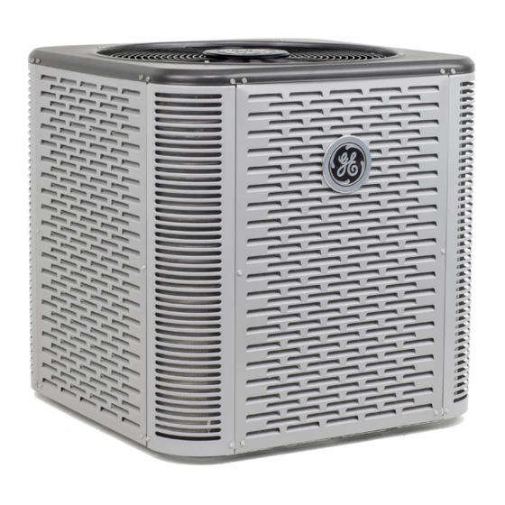
- Page 1 Service NS18AT TWO STAGE SPLIT SYSTEM AIR Manual CONDITIONER UP TO 17.8 SEER2 READ CAREFULLY. KEEP THESE INSTRUCTIONS 31-5000747 Rev. 0 11-22 GEA...
-
Page 2: Table Of Contents
SERVICE MANUAL NS18AT This is a safety alert symbol and should never be ignored. When you see this symbol on labels or in manuals, be alert to the potential for personal injury or death. WARNING Table of Contents Installation Clearances ...........3 Improper installation, adjustment, alteration, service or Model Number Identification ...........3 maintenance can cause property damage, personal injury... -
Page 3: Installation Clearances
Installation Clearances See NOTES NOTES: Service clearance of 30 in. (762 mm) must be maintained on one of the sides adjacent to the control box. Clearance to one of the other three sides must be 36 in. (914 mm) Clearance to one of the remaining two sides may be NOTES NOTES A clearance of 24 in. -
Page 4: Dimensions
UNIT DIMENSIONS (IN.) Dimensions (inch) Shipping Model Weight (Lbs.) A - Width B - Depth C - Height NS18A24T 28.25 28.25 29.25 NS18A36T 28.25 28.25 33.75 NS18A48T 32.25 32.25 33.75 NS18A60T 32.25 32.25 43.25 NOTE: Appearances may vary. SOUND RATINGS Estimated Sound Pressure (dBA) Approximate Distance Model... -
Page 5: Specifications
ACCESSORIES System Accessory Where Used Kit Number Purpose Prevents liquid migration to the compressor especially for high liquid riser Liquid Line Solenoid All models 60M52 applications Enables cooling demand down to 30 °F. Will require freeze stat, CC heater and Low Ambient (cooling operation) All models 34M72... -
Page 6: Typical Unit Parts Arrangement
Typical Unit Parts Arrangement FIGURE 1. Typical Plumbing Arrangement TABLE 1. Torque Requirements Operating Gauge Set and Service Valves Parts Recommended Torque TORQUE REQUIREMENTS Service valve cap 8 ft.- lb. 11 NM When servicing or repairing HVAC components, ensure Sheet metal screws 16 ft.- lb. - Page 7 SERVICE VALVES ANGLE AND BALL Operating Angle Type Service Valve: 1. Remove stem cap with an appropriately sized wrench. 2. Use a service wrench with a hex-head extension (3/16” for liquid line valve sizes and 5/16” for vapor line valve sizes) to back the stem out counterclockwise as far as it will go.
-
Page 8: Unit Placement
DETAIL B DETAIL A INSTALL UNIT LEVEL OR, IF ON A SLOPE, MAINTAIN SLOPE TOLERANCE INSTALL UNIT AWAY OF 2 DEGREES (OR 2 INCHES PER 5 FEET [50 MM PER 1.5 M]) AWAY FROM WINDOWS FROM BUILDING STRUCTURE. DISCHARGE AIR BUILDING STRUCTURE MOUNTING... -
Page 9: Removing And Installing Louvered Panels
Removing and Installing Louvered Panels WARNING To prevent personal injury, or damage to panels, unit or structure, be sure to observe the following: While installing or servicing this unit, carefully stow all removed panels out of the way, so that the panels will not cause injury to personnel, nor cause damage to objects or structures nearby, nor will the panels be subjected to damage (e.g., being bent or scratched). -
Page 10: New Or Replacement Line Set
Recommended topping-off POE oils are Mobil EAL ARC- New or Replacement Line Set TIC 22 CC or ICI EMKARATE RL32CF. This section provides information on new installation or re- MATCHING WITH NEW OR EXISTING INDOOR COIL placement of existing line set. If a new or replacement line AND LINE SET set is not required, then proceed to Brazing Connections The RFC1-metering line consisted of a small bore copper... - Page 11 LINE SET IMPORTANT — Refrigerant lines must not contact structure. INSTALLATION REFRIGERANT LINE SET — INSTALLING Line Set Isolation — The following illustrations are VERTICAL RUNS (NEW CONSTRUCTION SHOWN) examples of proper refrigerant line set isolation: NOTE — Insulate liquid line when it is routed through areas where the surrounding ambient temperature could become higher than the REFRIGERANT LINE SET —...
-
Page 12: Brazing Connections
IMPORTANT Brazing Connections Use the procedures outlined in figures 6 and 7 for brazing Allow braze joint to cool before removing the wet rag line set connections to service valves. from the service valve. Temperatures above 250ºF can damage valve seals. WARNING IMPORTANT Danger of fire. - Page 13 CAP AND CORE REMOVAL CUT AND DEBUR Cut ends of the refrigerant lines square (free from nicks or dents) Remove service cap and core from and debur the ends. The pipe must remain round. Do not crimp end both the suction / vapor and liquid line of the line.
- Page 14 WRAP SERVICE VALVES To help protect service valve seals during brazing, wrap water saturated cloths around service valve bodies and copper tube stubs. Use additional water saturated cloths underneath the valve body to protect the base paint. FLOW NITROGEN Flow regulated nitrogen (at 1 to 2 psig) through the refrigeration gauge set into the valve stem port connection on the liquid service valve and out of the suction / vapor valve stem port.
-
Page 15: Flushing Line Set And Indoor Coil
Flushing Line Set and Indoor Coil TYPICAL EXISTING FIXED ORIFICE TYPICAL EXISTING EXPANSION VALVE REMOVAL REMOVAL PROCEDURE (UNCASED PROCEDURE (UNCASED COIL SHOWN) COIL SHOWN) STUB END TWO PIECE PATCH PLATE LIQUID LINE CHECK DISTRIBUTOR TUBES (UNCASED COIL ONLY) ORIFICE EXPANSION LIQUID LINE ORIFICE HOUSING HOUSING VALVE... -
Page 16: Installing Indoor Metering Device
See the GE Appliances NS18AT Product Specification expansion valve. Refer to below illustration for reference bulletin for approved expansion valve kit match-ups. The during installation of expansion valve unit. -
Page 17: Leak Test Line Set And Indoor Coil
IMPORTANT Leak Test Line Set and Indoor Coil The Clean Air Act of 1990 bans the intentional venting WARNING of refrigerant (CFC’s and HCFC’s) as of July 1, 1992. Approved methods of recovery, recycling or reclaiming When using a high pressure gas such as must be followed. -
Page 18: Evacuating Line Set And Indoor Coil
Evacuating Line Set and Indoor Coil CONNECT GAUGE SET HIGH NOTE — Remove cores from service valves (if not already done). Connect low side of manifold gauge set with 1/4 SAE in-line tee to vapor line service valve Connect high side of manifold gauge set to liquid line service valve OUTDOOR MANIFOLD... -
Page 19: Electrical
IMPORTANT Electrical In the U.S.A., wiring must conform with current local codes Use a thermocouple or thermistor electronic vacuum and the current National Electric Code (NEC). In Canada, gauge that is calibrated in microns. Use an instrument wiring must conform with current local codes and the cur- capable of accurately measuring down to 50 microns. - Page 20 K1-1 NS18A24T GROUND START COMPRESSOR CAPACITOR NS18A36T CONTACTOR NS18A48T COMPRESSOR CONTACTOR POTENTIAL OUTDOOR FAN RELAY (LEADED) EQUIPMENT ORANGE-RUN (OPTIONAL) GROUND BLACK-COMMON PURPLE- DUAL CAPACITOR CAPACITOR EC MOTOR CONNECTION S87 LOW (NS18A60T) PRESSURE COMPRESSOR SWITCH HIGH NOTE- PRESSURE FOR USE WITH COPPER CONDUCTORS SWITCH ONLY.
-
Page 21: System Operation
System Operation Maintenance UNIT COMPONENTS DEALER IMPORTANT WARNING Some scroll compressors have an internal vacuum Electric Shock Hazard. Can cause injury or protector that will unload scrolls when suction pressure death. Unit must be properly grounded in goes below 20 psig. A hissing sound will be heard when accordance with national and local codes. - Page 22 Outdoor Coil (cont) Outdoor Coil The outdoor unit must be properly maintained to ensure its NOTICE ! proper operation. Failure to follow instructions will cause damage to • Please contact your dealer to schedule proper inspec- the unit. tion and maintenance for your equipment. This unit is equipped with an aluminum coil.
-
Page 23: Servicing Units Void Of Charge
2 - Inspect all factory and field-installed wiring for loose lications: connections. • GE Appliances NS18AT Product Specification bulletin 3 - After evacuation is complete, open the liquid line and suction line service valves to release the refrigerant • GE Appliances Product Catalog charge (contained in outdoor unit) into the system. - Page 24 Start-Up and Performance Checklist Customer Address Indoor Unit Model Serial Outdoor Unit Model Serial Notes: START UP CHECKS Refrigerant Type: Rated Load Amps: Actual Amps Rated Volts Actual Volts Condenser Fan Full Load Amps Actual Amps: COOLING MODE Suction Pressure: Liquid Pressure: Supply Air Temperature: Ambient Temperature: Return Air: Temperature:...
-
Page 25: Notes
Notes Page 25 31-5000747 Rev. 0... - Page 26 All specifications and illustrations subject to change without notice and without incurring obligations. Printed in the U.S.A.