Table of Contents
Quick Links
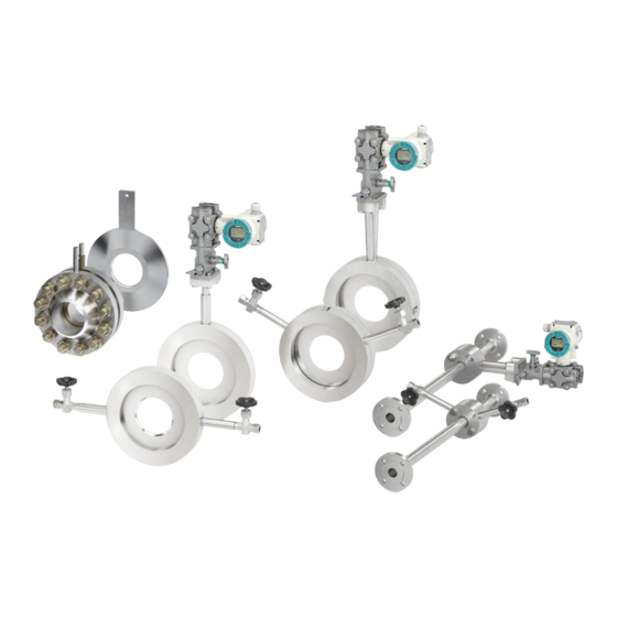
SITRANS FP
Primary elements according to
ISO 5167
for differential flow measurement
SITRANS FPS200
Operating Instructions
7ME17.8
08/2019
A5E46744245-AB
Introduction
General information
Checking the consignment
Nameplate layout
Installing/connecting
Commissioning
Troubleshooting
Appendix
1
2
3
4
5
6
7
8
Table of Contents

Related Manuals for Siemens SITRANS FP 7ME17.8


Summary of Contents for Siemens SITRANS FP 7ME17.8
- Page 1 Introduction General information Checking the consignment SITRANS FP Nameplate layout Primary elements according to ISO 5167 Installing/connecting for differential flow measurement SITRANS FPS200 Commissioning Operating Instructions Troubleshooting Appendix 7ME17.8 08/2019 A5E46744245-AB...
- Page 2 Note the following: WARNING Siemens products may only be used for the applications described in the catalog and in the relevant technical documentation. If products and components from other manufacturers are used, these must be recommended or approved by Siemens. Proper transport, storage, installation, assembly, commissioning, operation and maintenance are required to ensure that the products operate safely and without any problems.
- Page 3 Introduction SITRANS FPS200 Operating Instructions, 08/2019, A5E46744245-AB...
-
Page 4: Table Of Contents
Introduction Content Introduction ........................6 Document history ..........................6 Correct usage ............................6 General information ....................... 7 Safety information ..........................7 Qualified personnel ..........................7 Requirements for special usage ......................8 Special warnings ........................... 8 Checking the consignment ..................10 Nameplate layout ...................... - Page 5 Introduction 5.8.2 Disassembly of plug-in orifices ....................17 5.8.3 Disassembly of welded primary elements ................. 17 Commissioning ......................18 Usage of further components ......................18 6.1.1 Condensate vessels (for steam applications, if included in the scope of delivery) ....18 6.1.2 Shut off valves (if included in the scope of supply) ..............
-
Page 6: Introduction
Introduction 1 Introduction Document history The overview below summarizes the most important changes in the documentation when compared to the previous edition. Edition Note 04/2019 First edition 08/2019 Chapter “Nameplate layout” updated Correct usage The primary element is used to measure the volume or mass flow rate of gases, steam and liquids. The device may only be used for the purposes specified in these instructions. -
Page 7: General Information
This device may only be used for the applications described in the technical description and only in • connection with devices or components from other manufacturers which have been approved or recommended by Siemens. You are obliged to respect the test certificates, provisions and laws applicable in your country during •... -
Page 8: Requirements For Special Usage
Attention: If you need more information or have particular problems which are not covered sufficiently by the operating instructions, get in touch with Siemens directly (see last page). You may find contact information in the Internet. - Page 9 General information Improper mounting of the flow computer: Please observe that the components of the product are mounted properly. Improper mounting of the device: Please observe that the device and its components are mounted properly. Improper mounting of the tubes: In any case, the installation and operation has to be carried out only by qualified personal.
-
Page 10: Checking The Consignment
Checking the consignment Checking the consignment 1. Check the packaging and the delivered items for visible damages. 2. Report any claims for damages immediately to the shipping company. 3. Retain damaged parts for clarification. 4. Check the scope of delivery by comparing your order to the shipping documents for correctness and completeness. -
Page 11: Nameplate Layout
Nameplate layout 4 Nameplate layout Example ① Product name ⑥ Manufacture date ② Article number ⑦ Serial number ③ ⑧ Maximum allowable test pressure ④ Material ⑨ Maximum allowable operating temperature ⑤ Pipe inner diameter ⑩ Maximum allowable operating pressure Installing/connecting General information The following national regulations have to be observed at installation, especially:... -
Page 12: Positioning Of The Device
Installing/connecting Verify before assembling if the necessary upstream and downstream conditions are respected and verify the required mounting position (see 4.2.1 In- and outlet routes). Loose shut off valves (if delivered) have to be mounted on the pressure tapping nozzles of the primary element or for steam applications on the condensate vessels. -
Page 13: Size/Dimensions
Installing/connecting transportation must be avoided. In particular, pressure tapping nozzles, fittings, flange finish and painting have to be protected against scratching or other damage. Size/Dimensions Observe the dimension drawings of the primary elements. The serial number-specific dimension drawing can be found in PIA Life Cycle Portal. -
Page 14: Installation Of Primary Element For Welding-Ln
Installing/connecting Flange Removal The device is delivered with measuring flanges. The device may have to be disassembled for welding in the flange due to danger of improper heating. Welding in and inspecting the flange weld must be performed according to the state-of-the-art and under adherence of the applicable welding provisions (for example AD 2000). -
Page 15: Installation Position And Piping For Measurement In Liquids
Installing/connecting Assembling in horizontal pipes For flow rate measurement in gases, the differential pressure transmitter should be installed above the • center-line of the pipe at all times. An upwards vertical installation is preferred. For flow rate measurement in liquids, the differential pressure transmitter should be installed below the •... -
Page 16: Installation Position And Piping For Measurement In Steam
Installing/connecting For flow rate measurement in humid gases, installation of separators and discharge valves is sensible to catch and remove the condensate. 5.6.4 Installation position and piping for measurement in steam For flow rate measurement in steam use two condensation vessels. They must be at the same height. Usually, the condensation vessels as well as the initial shut-off valves are part of the delivery of primary elements for steam. -
Page 17: Disassembly
Installing/connecting Disassembly Before disassembly of primary elements, the process has to be stopped. Overpressure has to be avoided. Furthermore, general information (See chapter 1) has to be observed. The influence of the disassembly of the primary element on the whole system has to be considered. For primary elements in compact design with directly mounted transmitter, this has to be separated electronically and if necessary disassembled. -
Page 18: Commissioning
Commissioning 6 Commissioning Usage of further components 6.1.1 Condensate vessels (for steam applications, if included in the scope of delivery) Usage Usage of condensate vessels is recommended for gaseous media that turn liquid in the differential pressure lines when cooling off. This is the case especially for steam. Depending on pressure and temperature, it may occur as well with other media (for example alcohols). -
Page 19: Shut Off Valves (If Included In The Scope Of Supply)
Commissioning 6.1.2 Shut off valves (if included in the scope of supply) Shut off valves are used for initial shutoff of the measuring point. For high-pressure and high-temperature applications double initial shutoff may be recommended or prescribed depending on national regulations. Function Initial shutoff serves separation of the measuring system from the measuring line close to the process in case of a leak or maintenance work at the differential pressure lines. - Page 20 Commissioning Commissioning In the scope of commissioning, a zero point adjustment of the pressure transmitter must be provided for in all cases. At initial commissioning, all valves should be closed when starting up the process. Then the valves of the plus and minus sides must be opened carefully.
-
Page 21: Troubleshooting
Troubleshooting 7 Troubleshooting Pos. Description of faults Possible cause Primary element No or too low differential The primary element is not mounting in direction of the flow. pressure Connections of differential pressure between primary element and transmitter are inverted (the inlet side of the primary element is not connected with the plus side of the transmitter and the outlet side of the primary element is not connected with the minus side of the transmitter). - Page 22 (in case of Transmitter not mounted below the primary element measurement of steam and liquids). Condensate in the primary Default of the mounting of the primary element. element/pressure line and/or (in case of transmitter measurement of gases) Leakage A substitution of seals is only necessary in special cases, e.g. if aggressive or corrosive media are not compatible with the material of the seals.
-
Page 23: Appendix
Appendix 8 Appendix Certificates You can find certificates on the Internet at Certificates (http://www.siemens.com/processinstrumentation/certificates) or on an included DVD. Technical support If this documentation does not provide complete answers to any technical questions you may have, contact Technical Support at: Support request (http://www.siemens.com/automation/support-request)