Table of Contents
Quick Links
Table of Contents

Related Manuals for Sentera Controls DXH-G

Summary of Contents for Sentera Controls DXH-G
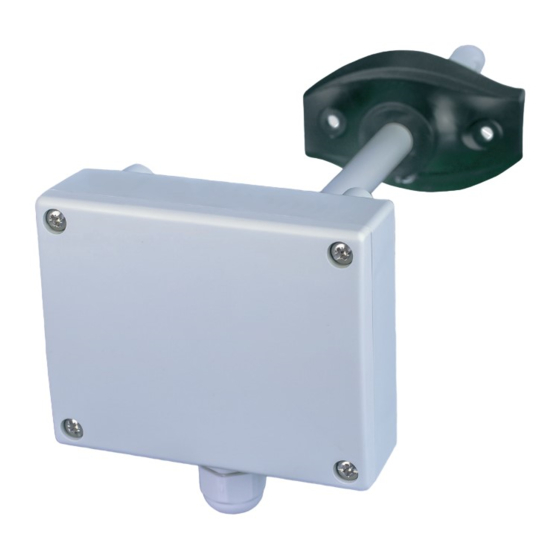
- Page 1 DUCT HUMIDITY SENSOR / SWITCH Mounting and operating instructions...
-
Page 2: Table Of Contents
DUCT HUMIDITY SENSOR / SWITCH Table of contents SAFETY AND PRECAUTIONS PRODUCT DESCRIPTION ARTICLE CODES INTENDED AREA OF USE TECHNICAL DATA STANDARDS OPERATIONAL DIAGRAMS WIRING AND CONNECTIONS MOUNTING INSTRUCTIONS IN STEPS MODBUS REGISTER MAPS VERIFICATION OF INSTALLATION INSTRUCTIONS TRANSPORT AND STOCK KEEPING INFORMATION WARRANTY INFORMATION AND RESTRICTIONS MAINTENANCE MIW-DXH-EN-001 - 02 / 10 / 2017... -
Page 3: Safety And Precautions
DUCT HUMIDITY SENSOR / SWITCH SAFETY AND PRECAUTIONS Read all the information, the datasheet, mounting and operating instructions and study the wiring and connection diagram before working with the product. For personal and equipment safety, and for optimum product performance, make sure you entirely understand the contents before installing, using, or maintaining this product. -
Page 4: Product Description
The unit is equipped with Modbus RTU (RS485) communication and has an analogue output and a relay output. ARTICLE CODES Code Supply Connection DXH-G 13—26 VAC 3-wire 18—34 VDC DXH-F 18—34 VDC 4-wire INTENDED AREA OF USE ■... -
Page 5: Operational Diagrams
DUCT HUMIDITY SENSOR / SWITCH OPERATIONAL DIAGRAMS Analogue output [VDC] Relay output rel on rel off SP-hyst SP rH, [%] min. max. rH, [%] range range WIRING AND CONNECTIONS Positive DC voltage / AC ~ Ground / AC ~ Modbus RTU (RS485) signal A Modbus RTU (RS485) signal /B Analogue output (0—10 VDC / 0—20 mA) Ground Normally open contact... - Page 6 DUCT HUMIDITY SENSOR / SWITCH Adjust the standalone settings: Select the sensor range by JP3. See Fig. 2 Sensor range selection jumper and the enclosed information. Select the desired relay switching point by setpoint trimmer VR1. (See Fig. 3.) Select the analogue output mode by JP5. (See Fig. 4.) To reset the Modbus settings, put and hold jumper P1 for 20 seconds.
- Page 7 DUCT HUMIDITY SENSOR / SWITCH Mount the unit outside a duct with the tube mounted inside the duct but fixed outside it. Mind the correct mounting position and unit dimensions. See Fig. 7 and Fig. 8. Fig. 7 Mounting dimensions Fig. 8 Mounting position Acceptable Not acceptable AIR FLOW...
-
Page 8: Modbus Register Maps
DUCT HUMIDITY SENSOR / SWITCH ATTENTION Do not exceed the maximum power supply rating! Measure before installation! Unregulated 24 VAC supply units provide higher nominal output voltage and activate the integrated fuse protection. ATTENTION If a G‑type article is using the same AC power supply source (transformer) as F‑type article, a SHORT CIRCUIT may result when the power supply and analogue signal terminals are connected to the same common ground! In this case always connect different article types to separate AC transformers or use the same... -
Page 9: Verification Of Installation Instructions
DUCT HUMIDITY SENSOR / SWITCH HOLDING REGISTERS Data type Description Data Default Values Device slave address unsigned int. Modbus device address 1—247 9.600 19.200 Modbus baud rate unsigned int. Modbus communication baud rate 1—4 38.400 4 = 57.600 Modbus parity unsigned int. Parity check mode 0—2 2 = ... -
Page 10: Transport And Stock Keeping Information
DUCT HUMIDITY SENSOR / SWITCH TRANSPORT AND STOCK KEEPING INFORMATION Avoid shocks and extreme conditions; stock in original packing. WARRANTY INFORMATION AND RESTRICTIONS Two years from the delivery date against defects in manufacturing. Any modifications or alterations to the product after the date of publication relieve the manufacturer of any responsibilities.