
Related Manuals for Electrolux DC6-8HP Q Series


Summary of Contents for Electrolux DC6-8HP Q Series
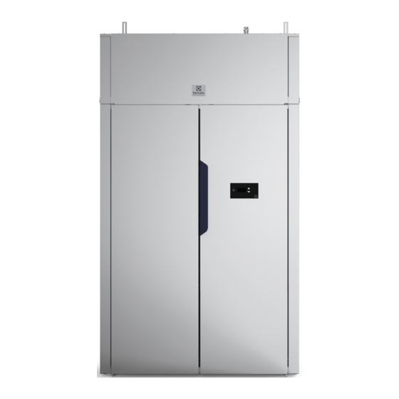
- Page 1 Installation manual Drying Cabinet DC6-8HP_Q 427001229/EN Original instructions 2022.05.25...
-
Page 3: Table Of Contents
Contents Contents 1 Safety Precautions ..........................5 General safety information......................5 Symbols............................5 2 Technical data.............................6 Dimensions drawing........................6 Technical data ...........................7 3 Delivery ..............................8 Dehumidifier unit ..........................9 Unpacking ..........................9 Installation kit ..........................9 Installation of upper part ......................10 5 Positioning/Attachment ........................12 Ventilating the room .........................12 Attachment to the wall ......................13 6 Electrical connection..........................14 Network Functions ........................15... -
Page 5: Safety Precautions
Installation manual 1 Safety Precautions This appliance can be used in public areas. Remove all objects from pockets such as lighters and matches. WARNING. This appliance is intended only for drying textiles washed in water. DO NOT MODIFY THIS APPLIANCE. Servicing shall be carried out only by authorized personnel. -
Page 6: Technical Data
Installation manual 2 Technical data 2.1 Dimensions drawing fig.W01385 1195 2061 1080 2079 Control panel Condensation nipple ⌀ 18 mm. 3 m hose included. -
Page 7: Technical Data
Installation manual 2.2 Technical data Capacity: kg of laundry 6 - 8 Drainage capacity: g/min* Electrical connection: 400V 3N AC 50Hz Traditional threaded fuse: Automatic fuse: Power: Hanging length: meters Weight: Sound pressure level: A-weighted emission sound pressure level <70 dB (A) Average heat emission per drying cycle used to assess ventilation need**: * 6 kg dry weight cotton, 50% residual moisture. -
Page 8: Delivery
Installation manual 3 Delivery The cabinet is delivered as two units on the same pallet, one upper part that includes the dehumidifier unit and one fully-assembled cabinet frame. 1220 1400 180 kg fig.W01386 Transport pallet Packaging, upper part Packaging, frame... -
Page 9: Dehumidifier Unit
Installation manual 4 Dehumidifier unit 4.1 Unpacking Removal all packing materials. Do not use sharp objects, as this could damage the product. Unpacked, the dehu- midifier unit weighs 82 kg. Packaging materials such as plastic and styrofoam should be kept out of reach of children. 4.2 Installation kit fig.W01372 Screw M8x20 (4). -
Page 10: Installation Of Upper Part
Installation manual 4.3 Installation of upper part Before lifting the upper part into place • Unscrew the lamp lens and the lamp from the upper part to prevent these from being damaged during setup. • Turn the hose nipple 90 degrees to protect this during setup as well. Upper part as seen from behind fig.W01387 Hose nipple... - Page 11 Installation manual The installation kit contains four air tubes that are used when installing the upper part. • Remove the cover plugs (A) and insert the air tubes (B) at the ends. Twist the air tubes so they lock into place. •...
-
Page 12: Positioning/Attachment
Installation manual 5 Positioning/Attachment The drying cabinet is only intended for placement indoors in a dry place The drying cabinet may not be placed in an environment where high-pressure water is used for cleaning The drying cabinet must stand level on a flat surface, resting on all four feet. Adjust the feet from the outside using a hex key. -
Page 13: Attachment To The Wall
Installation manual 5.2 Attachment to the wall The cabinet must be attached to the wall to prevent tipping. The installation kit contains two angle brackets that are mounted on the upper part of the drying cabinet as illustrated. Use the provided screws. The brackets have grooves for adjustment to the wall. Secure the cabinet to the wall. -
Page 14: Electrical Connection
Installation manual 6 Electrical connection The electrical installation may only be performed by qualified personnel. Electrical connection of the appliance must be done in accordance with electrical safety regulations. We recommend that the mains cable be equipped with a ground fault interrupter. The manufacturer disclaims all liability if the electrical connection is not done in the manner prescribed in this User Manual. -
Page 15: Network Functions
Installation manual 6.1 Network Functions Note! Can only be used on premium products. This product can be connected to ELS VISION or to an external payment system. fig.W01529 Connecting to ELS Vision Connect the network cables GND, RX, TX, 24V to the terminal block as illustrated. Connect the neutral position switch to terminal block positions 1 and 2, as illustrated. - Page 16 Installation manual Use the program buttons to move to Parameter 117, and enter the parameter using the Stop button. Set the parameter value to 1. This will activate the cabinet for network use. Use the Stop button to exit the parameter. To confirm the new settings: Press the Stop button and then Butterfly.
-
Page 17: Connection To Floor Drain
Installation manual 7 Connection to floor drain fig.W01390 Cabinet as view from behind with condensation hose attached Hose nipple Hole for hose in both sides of the cabinet Alternative hole for hose in both sides of the cabinet The cabinet is delivered from the factory with a condensation drain connection on the rear of the cabinet. Thread the supplied condensation hose on the hose nipple and route it to the floor drain. -
Page 18: Function Check
Installation manual 8 Function check May only be performed by qualified personnel. A function check must be performed when the installation is finished and before the appliance can be used. Whenever a repair has been made, a function check must be performed before the appliance can be used again. •... -
Page 19: Disposal Information
Installation manual 9 Disposal information 9.1 Disposal of appliance at end of life Before disposing of the machine, make sure to carefully check its physical condition, and in particular any parts of the structure that can give or break during scrapping. The machine’s parts must be disposed of in a differentiated way, according to their different characteristics (e.g. - Page 20 Electrolux Professional AB 341 80 Ljungby, Sweden www.electroluxprofessional.com...