Raycap PowerPlus System 100-3-1U Series Installation Instructions Operations Manual
Hide thumbs
Also See for PowerPlus System 100-3-1U Series:
- Installation instructions operations manual (36 pages)

Related Manuals for Raycap PowerPlus System 100-3-1U Series

Summary of Contents for Raycap PowerPlus System 100-3-1U Series
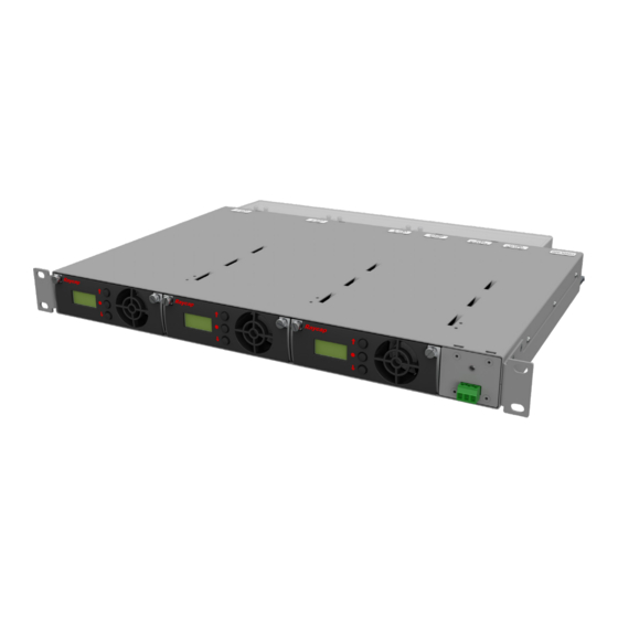
- Page 1 PowerPlus System 100-3-1U INSTALLATION INSTRUCTION & OPERATION MANUAL INSTALLATION INSTRUCTION & OPERATION MANUAL PowerPlus System 100-3-1U Series 100-3-1U-3 100-3-1U-2 www.raycap.com...
-
Page 3: Table Of Contents
Initial Settings Menu: Mode Selection .....................19 Parallel Mode Settings ..........................20 10. Single Mode Settings ..........................21 11. Live Settings Menu ...........................22 12. Bus Bar ..............................24 13. Alarms ...............................25 © Raycap | All rights reserved. • (320-1398) QRC | Rev.B www.raycap.com Page 1 of 30... -
Page 4: Copyright
Disclaimer The information in this document is subject to change without notice and describes only the product defined in the introduction of this documentation. This documentation is intended for the use of Raycap customers only for the purposes of the agreement under which the document is submitted, and no part may be used, reproduced, modified or transmitted in any form or means without the prior written permission of Raycap. The documentation has been prepared to be used by professional and properly trained personnel, and the customer assumes full responsibility when using it. -
Page 5: Introduction
® electrical protection at the RRH and BBU. PowerPlus is Raycap’s solution for power transmission to the RRH units of a DAS Telecommunication site. PowerPlus is a system installed at the PSU output that boosts the voltage at the base of a cellular site to overcome the voltage drop on the DC power cables that provide power to the RRHs. -
Page 6: Mounting
Select a suitable position for the installation of the unit. You will need 1U vertical space. The unit ships with a Rack Extension Kit to mount into a 23" rack. Mount the unit on the rack. (320-1398) QRC | Rev.B • © Raycap | All rights reserved. www.raycap.com Page 4 of 30... - Page 7 Mounting Position A1 Mounting Position A2 2.74 2.14 Mounting Position A3 Mounting Position A4 Release the 4 push pins and remove touch guard as shown below. © Raycap | All rights reserved. • (320-1398) QRC | Rev.B www.raycap.com Page 5 of 30...
-
Page 8: General Description
The voltage output of each module is intended to be connected to individual loads when the device is configured to operate in Single Mode. • The module outputs may be connected in parallel when the device is configured to operate in Parallel Mode. In this configuration, the load is shared between the installed modules. (320-1398) QRC | Rev.B • © Raycap | All rights reserved. www.raycap.com Page 6 of 30... -
Page 9: System Topology
PowerPlus System 100-3-1U INSTALLATION INSTRUCTION & OPERATION MANUAL System Topology -48VDC -48VDC -48VDC -48VDC OUT 1 OUT 2 OUT 3 © Raycap | All rights reserved. • (320-1398) QRC | Rev.B www.raycap.com Page 7 of 30... -
Page 10: Installation Configurations
Installation Configurations SINGLE MODE -48VDC OUT 3 -48VDC -48VDC OUT 2 -48VDC OUT 1 RTN OUT PARALLEL MODE -48VDC -48VDC OUT RTN OUT PowerPlus 100-3-1U system configurations (320-1398) QRC | Rev.B • © Raycap | All rights reserved. www.raycap.com Page 8 of 30... -
Page 11: Module Configurations
Power Plus All PowerPlus terminal connections are ¼-20 studs. Torque to 65 in-lbs. 100 AMP Module Installed RTMDC-5634-PF-48 RNSNDC-7771-PF-48 RTMDC-4983-RM-48 Trunk to Upper OVP © Raycap | All rights reserved. • (320-1398) QRC | Rev.B www.raycap.com Page 9 of 30... - Page 12 All PowerPlus terminal connections are ¼-20 studs. Torque to 65 in-lbs. 100 AMP 100 AMP Module Module Installed Installed RTMDC-5634-PF-48 RNSNDC-7771-PF-48 RTMDC-4983-RM-48 Trunk to Upper OVP (320-1398) QRC | Rev.B • © Raycap | All rights reserved. www.raycap.com Page 10 of 30...
- Page 13 All PowerPlus terminal connections are ¼-20 studs. Torque to 65 in-lbs. 100 AMP 100 AMP Module Module Installed Installed RTMDC-5634-PF-48 RNSNDC-7771-PF-48 RTMDC-4983-RM-48 Trunk to Upper OVP © Raycap | All rights reserved. • (320-1398) QRC | Rev.B www.raycap.com Page 11 of 30...
- Page 14 ¼-20 studs. Torque to 65 in-lbs. 100 AMP 100 AMP 100 AMP Module Module Module Installed Installed Installed RTMDC-5634-PF-48 RNSNDC-7771-PF-48 RTMDC-4983-RM-48 Trunk to Upper OVP (320-1398) QRC | Rev.B • © Raycap | All rights reserved. www.raycap.com Page 12 of 30...
- Page 15 ¼-20 studs. Torque to 65 in-lbs. 100 AMP 100 AMP 100 AMP Module Module Module Installed Installed Installed RTMDC-5634-PF-48 RNSNDC-7771-PF-48 RTMDC-4983-RM-48 Trunk to Upper OVP © Raycap | All rights reserved. • (320-1398) QRC | Rev.B www.raycap.com Page 13 of 30...
-
Page 16: System Management
The primary module in the parallel mode will display the input and output voltage of the system. The • Secondary modules will display the “Module 1” and “Module 2” messages. Parallel Mode – Primary Module Parallel Mode – Secondary Module (320-1398) QRC | Rev.B • © Raycap | All rights reserved. www.raycap.com Page 14 of 30... -
Page 17: Module Failure
When this occurs, the current Primary module will transfer output voltage to the new module. The new module will be configured as a new Secondary module. • The alarm will disappear after pressing the ‘ENTER’ button on the current Primary module for more than 3 seconds. © Raycap | All rights reserved. • (320-1398) QRC | Rev.B www.raycap.com Page 15 of 30... -
Page 18: Modules
INSTALLATION INSTRUCTION & OPERATION MANUAL Modules Module Replacement • Unscrew the thumb screws on both sides of the module. • Release the side levers. • Extract the module. (320-1398) QRC | Rev.B • © Raycap | All rights reserved. www.raycap.com Page 16 of 30... -
Page 19: Cold Module Replacement
• If there is a cold module installation in open slot(s), then the system will prompt for initial settings during power ON. © Raycap | All rights reserved. • (320-1398) QRC | Rev.B www.raycap.com Page 17 of 30... -
Page 20: Module Settings
Slot 2 Slot 3 • The Primary module is selected by pressing the ‘ENTER’ button of any module (e.g. Slot 1 module). This module will become the primary module and the other modules will be configured as Secondary modules. ENTER (320-1398) QRC | Rev.B • © Raycap | All rights reserved. www.raycap.com Page 18 of 30... -
Page 21: Initial Settings Menu: Mode Selection
Primary module. The selection is applied by pressing the ‘ENTER’ button on the Primary module. Up/Down Slot 2 Slot 3 Slot 1 Primary • The buttons on the Secondary modules (Slot 2, Slot 3) are disabled until slot 1 configuration is complete, and display the “SETTINGS” message. © Raycap | All rights reserved. • (320-1398) QRC | Rev.B www.raycap.com Page 19 of 30... -
Page 22: Parallel Mode Settings
Finish-Output Voltage Selection Finish • When all modules have been configured, the system starts the single mode operation cycle. Slot 1 Slot 2 Slot 3 Primary Main Single Mode Operation Slot 1 Slot 2 Slot 3 Primary (320-1398) QRC | Rev.B • © Raycap | All rights reserved. www.raycap.com Page 20 of 30... -
Page 23: Single Mode Settings
Set Finish • When all modules have been configured, the system starts the operating in Single mode. Slot 1 Slot 2 Slot 3 Primary Main Single Mode Operation Slot 1 Slot 2 Slot 3 Primary © Raycap | All rights reserved. • (320-1398) QRC | Rev.B www.raycap.com Page 21 of 30... -
Page 24: Live Settings Menu
‘UP’ or ‘DOWN’ buttons on the Primary module. The selection is applied by pressing the ‘ENTER’ button on the Primary module. Up/Down Slot 2 Slot 3 Slot 1 Primary (320-1398) QRC | Rev.B • © Raycap | All rights reserved. www.raycap.com Page 22 of 30... - Page 25 Primary modules is the Mode selection. • At this stage the modules can be configured independently with the same proceeding steps as for the initial settings menu. Slot 1 Slot 2 Slot 3 Primary Slot 1 Slot 2 Slot 3 Primary © Raycap | All rights reserved. • (320-1398) QRC | Rev.B www.raycap.com Page 23 of 30...
-
Page 26: Bus Bar
The bus bar must be removed when the • The bus bar must be installed when the Single Mode is selected. Parallel Mode is selected. (320-1398) QRC | Rev.B • © Raycap | All rights reserved. www.raycap.com Page 24 of 30... -
Page 27: Alarms
Alarm Condition Closed Normally Closed Alarm Condition Open NOTE: Primary Module Failure and Secondary Module Failure is detailed in the System Management section of this document. © Raycap | All rights reserved. • (320-1398) QRC | Rev.B www.raycap.com Page 25 of 30... - Page 28 Primary module will display the “IN VLT HIGH” message if this condition is sustained for more than 3 seconds. The alarm is automatically cleared when the input voltage returns to its normal operational level. (320-1398) QRC | Rev.B • © Raycap | All rights reserved. www.raycap.com Page 26 of 30...
- Page 29 Primary module and take over control as the new Primary module and raise the “PRIMARY FAILURE” alarm. Halted Primary Module New Primary Module © Raycap | All rights reserved. • (320-1398) QRC | Rev.B www.raycap.com Page 27 of 30...
- Page 30 13.10 Forced By-Pass Condition • When the system goes to by-pass mode without the control of the module, the module will display the “FORCED BY-PASS” message. (320-1398) QRC | Rev.B • © Raycap | All rights reserved. www.raycap.com Page 28 of 30...
- Page 31 PowerPlus System 100-3-1U INSTALLATION INSTRUCTION & OPERATION MANUAL Notes © Raycap | All rights reserved. • (320-1398) QRC | Rev.B www.raycap.com Page 29 of 30...
- Page 32 PowerPlus System 100-3-1U INSTALLATION INSTRUCTION & OPERATION MANUAL (320-1398) QRC | Rev.B • © Raycap | All rights reserved. www.raycap.com Page 30 of 30...