Table of Contents
Quick Links
Table of Contents

Related Manuals for GE Marquette 418793-001


Summary of Contents for GE Marquette 418793-001
- Page 1 APEX Telemetry Transmitter Service Manual 401566-166 Revision D...
- Page 2 TRAM-NET, TRAM-RAC, TRAMSCOPE, TRIM KNOB, Trimline, UNION STATION, UNITY logo, UNITY NETWORK, Vari-X, Vari-X Cardiomatic, VariCath, VARIDEX, VAS, and Vision Care Filter are trademarks of GE Marquette Medical Systems, Inc. registered in the United States Patent and Trademark Office. 12SL, 15SL, Access, AccuSpeak, ADVANTAGE, BAM, BODYTRODE, Cardiomatic, ®...
-
Page 3: Table Of Contents
CONTENTS INTRODUCTION ......... 1-1 Manual Information . - Page 4 CONTENTS MAINTENANCE ......... 3-1 Disinfection .
- Page 5 CONTENTS TROUBLESHOOTING ........4-1 Controlling Electrostatic Discharge Damage ....4-2 About CMOS Components .
- Page 6 CONTENTS UPPER LEVEL ASSEMBLY ....... 6-1 General ..........6-2 Versions of the Assembly .
- Page 7 CONTENTS OXIMETER ASSEMBLY ........8-1 General ..........8-2 Versions of the Assembly .
- Page 8 CONTENTS APEX Telemetry Transmitter Revision D 401566-166...
-
Page 9: Introduction
INTRODUCTION CONTENTS Manual Information ........1-2 Revision History . -
Page 10: Manual Information
This manual does not include extensive information on the circuit boards that comprise the transmitter assembly. These assemblies are not field repairable and require return to a GE Marquette service facility for any repairs. APEX Telemetry Transmitter Revision D... -
Page 11: Safety Information
INTRODUCTION: Safety Information Safety Information Responsibility of the GE Marquette Medical Systems is responsible for the effects of safety, reliability, and performance only if: Manufacturer • assembly operations, extensions, readjustments, modifications, or repairs are carried out by persons authorized by GE Marquette Medical Systems, Inc;... -
Page 12: Equipment Symbols
INTRODUCTION: Safety Information Equipment Symbols The following symbols appear on the transmitter. ATTENTION: Consult accompanying documents before using the equipment. Warnings, Cautions, Warnings, cautions, and notes are used throughout this manual to designate a degree or level of hazardous situations. Hazard is defined as and Notes a source of potential injury to a person. -
Page 13: Service Information
Any unauthorized attempt to repair equipment under warranty voids that warranty. • It is the user’s responsibility to report the need for service to GE Marquette Medical Systems or to one of their authorized agents. • Failure on the part of the responsible individual, hospital, or... -
Page 14: How To Reach Us
INTRODUCTION: How to Reach Us How to Reach Us Customer Support If you have questions about your monitoring equipment or if you need service for equipment repair call: and Equipment Repair Information U.S.A and Canada: 800-558-7044 (24-hour service) Other countries: 561-575-5000 (during U.S. -
Page 15: Equipment Overview
EQUIPMENT OVERVIEW CONTENTS Overview ..........2-2 Features . -
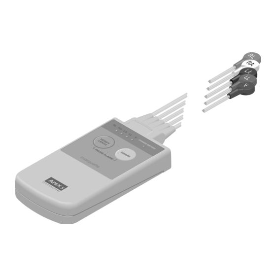
Page 16: Overview
EQUIPMENT OVERVIEW: Overview Overview Features The APEX S transmitter is designed to collect ECG data from a patient and relay that information to a receiver assembly. Either one or three ECG leads are gathered. With a three-wire leadwire set, the transmitted signal can be either lead I, II, or III. -
Page 17: Indicators
EQUIPMENT OVERVIEW: Overview Indicators The APEX transmitter indicators are described below. • CHANGE BATTERY LED. This indicator begins to flash when the battery voltage level drops below 1.9 Volts. The batteries should be replaced within 30 minutes after the CHANGE BATTERY LED begins flashing. -
Page 18: Apex Oximeter Accessory
EQUIPMENT OVERVIEW: APEX Oximeter Accessory APEX Oximeter Accessory An optional accessory to the Apex S transmitter is the APEX Oximeter attachment as shown below. Interconnection Do the following to connect the APEX oximeter to the APEX S transmitter. 1. Connect the SpO probe to the APEX oximeter by plugging the non- sensor end of the probe into the 9-pin connector on the top of the APEX oximeter. -
Page 19: Indicators
EQUIPMENT OVERVIEW: APEX Oximeter Accessory Indicators The APEX oximeter indicators are described below. Digital Display Perfusion LED Power Display On/Off 310A • POWER. Pressing the POWER button turns ON the battery power to the APEX oximeter. To turn OFF all power to the APEX oximeter, press and hold the POWER button for two seconds. -
Page 20: Technical Specifications
EQUIPMENT OVERVIEW: Technical Specifications Technical Specifications Physical Specifications Item Description Height 12.7 cm (5.0 in) Width 6.9 cm (2.7 in) Depth 2.0 cm (0.8 in) Weight 130 grams (4.6 ounces) without batteries or leadwires Environmental Specifications Item Description Operating ambient 0°... -
Page 21: Underwriters Laboratory, Inc
EQUIPMENT OVERVIEW: Technical Specifications APEX Oximeter Specifications Item Description Oxygen Saturation 0 to 100% Range Pulse Rate Range 18 to 300 pulses per minute Displays Patient Indicator: PERFUSION LED Digital Display: 3-digit 7-segment LEDs Measurement Red 660 Nanometers Wavelengths Infrared 910 Nanometers Accuracy 70-100% ±3% of full scale. - Page 22 EQUIPMENT OVERVIEW: Technical Specifications For your notes APEX Telemetry Transmitter Revision D 401566-166...
-
Page 23: Maintenance
MAINTENANCE CONTENTS Disinfection ..........3-2 Equipment Maintenance Program . -
Page 24: Disinfection
MAINTENANCE: Disinfection Disinfection Disinfection of the transmitter assembly must be performed in accordance with the policies and procedures of your institution’s infection control or biomedical staff. NOTE The transmitter and leadwires should be inspected for damage before they are used on any new patients. This inspection is vital to maintain the integrity of the transmitter’s environmental seals. -
Page 25: Equipment Maintenance Program
Verify the unit is working properly according to the “Checkout Procedure” presented in this chapter. Recommended To help you establish a systematic maintenance routine, GE Marquette Medical Systems recommends that you perform all maintenance Frequency procedures presented in this chapter:... -
Page 26: Visual Inspection
MAINTENANCE: Visual Inspection Visual Inspection The following steps check for obvious damage. • Inspect the transmitter case for cracks or other damage. Do not use a transmitter that is damaged. • Inspect the transmitter case for damage that may affect the environmental seals (such as the unit was dropped and the case seals opened as a result of the impact). -
Page 27: Cleaning
MAINTENANCE: Cleaning Cleaning The transmitter should be cleaned on a regular basis. The exterior surfaces may be cleaned with a dampened, lint-free cloth. Use one of the following cleaning solutions: • ammonia (diluted according to manufacturer’s recommendations), • Cidex, • sodium hypochlorite bleach (diluted), or •... -
Page 28: Checkout Procedure
MAINTENANCE: Checkout Procedure Checkout Procedure This procedure describes a series of performance tests for the APEX Transmitter and optional APEX oximeter. Required Test The following equipment is required. Equipment • ECG simulator • Fresh alkaline “AA” batteries • Low-battery simulator, or low-voltage “AA” batteries (1.86 V maximum for 2 batteries), or low-voltage variable power supply •... -
Page 29: Rf Power Shutdown
MAINTENANCE: Checkout Procedure RF Power Shutdown This test verifies that the transmitter reduces its output when an all- leads-fail condition lasts more than six seconds. 1. Connect the transmitter to an ECG source. 2. Install batteries in the transmitter. 3. At a central station verify that the transmitter is sending the ECG source’s signals properly. -
Page 30: Battery Current Draw
MAINTENANCE: Checkout Procedure Battery Current Draw This test measures the transmitter current draw in both normal operation and during an all-leads-fail condition. 1. Disconnect the APEX RF test cable from the transmitter. 2. At point B (see the figure on the preceding page) adjust the low- voltage power supply output to 3.0V. -
Page 31: Rf Test
MAINTENANCE: Checkout Procedure RF Test Setup The following series of tests verify operation of the transmitter’s RF circuitry. The RF monitor and the APEX RF test cable should be prepared as shown in the following diagram. Configure the RF monitor as follows: 1. -
Page 32: Sideband Balance
MAINTENANCE: Checkout Procedure Sideband Balance This test verifies that the main sideband lobes are within 1 dB (amplitude) of each other. 1. While holding the VERIFY LEADS button down, install batteries in the transmitter. This starts the transmitter in the square-wave mode. -
Page 33: Carrier Frequency Error
MAINTENANCE: Checkout Procedure Carrier Frequency Error This test checks the carrier frequency to verify that it is within the programmed range. 1. Set the RF monitor to measure 2-kHz/division horizontal. 2. Set the meter to the 2-kHz per division scale. 3. -
Page 34: Communications Tests
MAINTENANCE: Checkout Procedure Communications The following series of tests verify that the transmitter is operating properly with the receiving system and the monitoring network. A Tests central station that has access to the receiver system is required. Lead(s) Fail This test verifies that the transmitter can test for, and indicate, good lead signals. -
Page 35: Pause Alarm
MAINTENANCE: Checkout Procedure Pause Alarm This test verifies that the transmitter enters into the PAUSE ALARMS condition for approximately five minutes. 1. With the transmitter operating, press the GRAPH and VERIFY LEADS buttons simultaneously. The LEAD STATUS and CHANGE BATTERY LEDs should flash twice to acknowledge the switch was pressed. -
Page 36: Change Battery Message
5. Verify that a CHANGE BATTERY message is displayed on the central station. Completion If the transmitter fails any of the above tests, return it to GE Marquette for repair. Oximeter Do the following to ensure the functionality of the APEX oximeter. -
Page 37: Completion
Centralscope. Accutracker DX NIBP Operational Tests NOTE If the Accutracker fails any test, return the unit to GE Marquette Medical Systems Service and Supplies. See “How to Reach Us” in Chapter 1. Accutracker Display The following displays on the Accutracker when you turn it on (press and hold the button while turning the switch on). -
Page 38: Over-Pressure Release Check
MAINTENANCE: Checkout Procedure 2. Press and hold the button and turn the Accutracker on. The unit is now in Technical Calibrate mode and valve #1 is closed. 3. Apply pressures to the Accutracker between 0mmHg and 250mmHg in increments of 50mmHg. Make sure there is no more than a +/– 2mmHg difference between the mercury column or PDM200 display and the Accutracker display value. -
Page 39: Hardware Time-Out And System Leak Check
MAINTENANCE: Checkout Procedure Hardware Time-Out and 1. Press and hold the button and turn the Accutracker on. System Leak Check NOTE Make sure no external pressure is applied to the Accutracker when you turn it on. 2. Apply 200mmHg pressure to the Accutracker pressure circuit and start a timer to clock the Hardware Time-Out circuit. -
Page 40: Pm Inspection Form
(PM) form is no longer printed with this manual. For the latest PM form regarding this product, contact GE Marquette Service. If repairs/adjustments are made or you replace any parts, describe this in the area provided on the PM form. -
Page 41: Repair Log
MAINTENANCE: Repair Log Repair Log Institution Name: Unit Name: Date Maintenance/Repair Technician Revision D APEX Telemetry Transmitter 3-19 401566-166... - Page 42 MAINTENANCE: Repair Log Institution Name: Unit Name: Date Maintenance/Repair Technician 3-20 APEX Telemetry Transmitter Revision D 401566-166...
-
Page 43: Troubleshooting
TROUBLESHOOTING CONTENTS Controlling Electrostatic Discharge Damage ....4-2 About CMOS Components ....... . 4-2 Reducing ESD Damage . -
Page 44: Controlling Electrostatic Discharge Damage
TROUBLESHOOTING: Controlling Electrostatic Discharge Damage Controlling Electrostatic Discharge Damage About CMOS All components of the Accutracker DX NIBP unit make extensive use of CMOS components. CMOS components are used because they are more Components immune to noise and consume less power than standard TTL or NMOS components. -
Page 45: Before Calling For Service
TROUBLESHOOTING: Before Calling for Service Before Calling for Service Before calling for service on a transmitter that may appear to be operating incorrectly or to have failed, check the following: Transmitter Frequent Lead Fail • Swap the leadwire set with either a new set or a known good set. Leadwires may have hidden internal damage that can cause signal Events failure. -
Page 46: Oximeter
TROUBLESHOOTING: Before Calling for Service • If, after working through the above steps, your transmitter still has a short battery life, a call for service may be necessary. Oximeter Check to see if the probe is disconnected from the APEX Oximeter or if “Check Probe”... -
Page 47: No Spo Data
TROUBLESHOOTING: Before Calling for Service No SpO Data • Version 6 software for the CDT-LAN is required. Verify the code is correct • APEX S transmitter is required. APEX 3 and APEX 5 transmitters do not function with the APEX Oximeter •... -
Page 48: Powerup Selftests
TROUBLESHOOTING: Powerup Selftests Powerup Selftests Transmitter The APEX transmitter performs a limited amount of testing of the internal memory components when it powers up. The results of these tests are indicated by the LEDs on the transmitter case. Test results may also be viewed on a remote terminal or personal computer if the APEX programming box is connected and in use. -
Page 49: Oximeter
TROUBLESHOOTING: Powerup Selftests 3. Finally, the transmitter’s frequency synthesizer is programmed with the specified customer’s frequency. A test is performed to verify a successful lock of the synthesizer circuits. If the synthesizer lock test passes the transmitter starts normal operation. If the synthesizer lock test fails, all of the LEDs on the transmitter are flashed. -
Page 50: Power Shutdown During Leads Fail
TROUBLESHOOTING: Power Shutdown During Leads Fail Power Shutdown During Leads Fail Transmitter If all leads fail for more than about six seconds the microprocessor shuts off power supplied to the RF modulator circuitry. This reduces the battery discharge rate when no data actually transmits. Once the leads are reconnected, about one second is required for the microprocessor to power up the modulator circuitry and resume transmitting patient data. -
Page 51: Calibration
CALIBRATION CONTENTS Programming the Transmitter for Use ......5-2 Procedure ..........5-2 Completion . -
Page 52: Programming The Transmitter For Use
CALIBRATION: Programming the Transmitter for Use Programming the Transmitter for Use The APEX transmitter can be programmed in the field to select both the operating frequency and the reference lead. The latter part of this section contains data on the operating frequencies and the TTX numbers that correspond to them. -
Page 53: Completion
CALIBRATION: Programming the Transmitter for Use 8. If a synthesizer lock error message is displayed after programming, verify the frequency setting is within the operating range of the transmitter. The complete frequency range for each transmitter is printed inside the battery compartment. If the transmitter is set correctly and the lock error message persists, the unit requires factory servicing. -
Page 54: Accutracker Calibration
Operational Tests” in Chapter 3, “Maintenance,” when you receive the Accutracker and every 12 months thereafter. If the unit fails, return the unit to GE Marquette Medical Systems Service and Supplies. See “How to Reach Us” in Chapter 1. APEX Telemetry Transmitter... -
Page 55: Upper Level Assembly
UPPER LEVEL ASSEMBLY CONTENTS General ..........6-2 Versions of the Assembly . -
Page 56: General
UPPER LEVEL ASSEMBLY: General General Versions of the There are four versions of the APEX S transmitter assembly. Make sure to reference the correct parts list and exploded view for your version of Assembly transmitter. Four versions of the transmitter PCB are presented in the next chapter. -
Page 57: Theory Of Operation
UPPER LEVEL ASSEMBLY: Theory of Operation Theory of Operation Overview This theory of operation is written for APEX telemetry transmitter assemblies pn 418793-001/002/003/004 using the schematic diagram of the transmitter PCB, pn 801278-001/002/004, found in Chapter 7, “Transmitter PCB.” The APEX telemetry transmitter acquires three differential leads of ECG information and a pace channel from the patient and converts this information to 10-bit NRZI digital data. - Page 58 UPPER LEVEL ASSEMBLY: Theory of Operation The following block diagram provides a more detailed analysis of the three general sections of circuitry. APEX Telemetry Transmitter Revision D 401566-166...
-
Page 59: Ecg Circuitry
UPPER LEVEL ASSEMBLY: Theory of Operation ECG Circuitry The ECG circuitry consists of three amplifier stages and a pace stage. First Amplifier Stage The first amplifier stage is a unity gain buffer for each of the four patient lead inputs. Low leakage diodes CR4, CR100, CR103, and CR106 protect against damage due to defibrillation and static pulses (sheet 1). -
Page 60: Digital Circuitry
UPPER LEVEL ASSEMBLY: Theory of Operation This amplifier generates a mirror image of the programmable reference voltage about the analog virtual ground (+1.25V) potential. For example, if the programmable reference voltage output is set to +0.5V with respect to analog ground (+1.75V absolute), the reference voltage inverter circuit will generate -0.5V with respect to analog ground (+0.75V absolute). -
Page 61: Modulator Drive And Filter Circuit
UPPER LEVEL ASSEMBLY: Theory of Operation Power Supply Circuit A diode (CR102) is connected across the batteries to protect the transmitter in the event of battery reversal (sheet 7). A zener diode across each supply voltage (CR6, CR7, CR8) protects against overvoltage due to static or defibrillation. -
Page 62: Phase Locked Loop
UPPER LEVEL ASSEMBLY: Theory of Operation Phase Locked Loop The phase-locked loop frequency synthesizer generates a sinusoidal carrier signal at a programmed frequency as presented in the table below for modulation by the digital data signal. The phase-locked loop frequency synthesizer consists of a phase-locked loop section, a passive loop filter section, and a voltage controlled oscillator section. -
Page 63: Frequency Doubler
UPPER LEVEL ASSEMBLY: Theory of Operation The VCO section generates a frequency based on the tuning voltage from the loop filter. A form of Colpitts oscillator is used, with the oscillator output frequency being controlled by the varactor diode CR1 (for -001/ 002/003 and CR9 for -004) capacitance value. -
Page 64: Frequency Modulator
UPPER LEVEL ASSEMBLY: Theory of Operation Frequency Modulator The frequency modulator section phase modulates the carrier signal, from the frequency doubler, using the low-pass filtered digital data input from the transmit data filter. This is done using mixer U1 as a phase modulator. -
Page 65: Exploded View Pn 418793-001A/002A/003A/004A
UPPER LEVEL ASSEMBLY: Exploded View PN 418793-001A/002A/003A/004A Exploded View PN 418793-001A/002A/003A/004A Sheet 1 of 3 Revision D APEX Telemetry Transmitter 6-11 401566-166... - Page 66 UPPER LEVEL ASSEMBLY: Exploded View PN 418793-001A/002A/003A/004A Sheet 2 of 3 6-12 APEX Telemetry Transmitter Revision D 401566-166...
- Page 67 UPPER LEVEL ASSEMBLY: Exploded View PN 418793-001A/002A/003A/004A Sheet 3 of 3 Revision D APEX Telemetry Transmitter 6-13 401566-166...
-
Page 68: Block Diagram Pn 418793-001A/002A/003A/004A
UPPER LEVEL ASSEMBLY: Block Diagram PN 418793-001A/002A/003A/004A Block Diagram PN 418793-001A/002A/003A/004A 6-14 APEX Telemetry Transmitter Revision D 401566-166... - Page 69 UPPER LEVEL ASSEMBLY: Parts List PN 418793-001A/002A/003A/004A Parts List PN 418793-001A/002A/003A/004A Reference Item Designation Parts List Part Number Gasket, Socket, Transmitter 411206-001 Cover, Transmitter 411732-001 Battery Door, Transmitter 411733-002 Contact, Battery, Single 411734-001 Contact, Battery, Double 411735-001 Socket, Single Contact 411737-001 Socket, Double Contact 411738-001...
- Page 70 UPPER LEVEL ASSEMBLY: Parts List PN 418793-001A/002A/003A/004A Reference Item Designation Parts List Part Number Label, Back, Transmitter, AHA (Determined by 418648-001 Destination) Label, Back, Transmitter, IEC (Determined by 418648-002 Destination) Label, Back, Transmitter, Intl, AHA (Determined by 418648-003 Destination) PCB Label, Serial Number 3710-102 Silicone Compound, DOW III 4851-059...
-
Page 71: Transmitter Pcb
TRANSMITTER PCB CONTENTS General ..........7-2 Versions of the Circuit Board . -
Page 72: General
TRANSMITTER PCB: General General Versions of the There are four versions of the transmitter PCB. Make sure to reference the correct parts list, parts location, and schematic pages for your version Circuit Board of the PCB. Schematic Part Number Part Number Frequency Type Comments 801278-001 SD801278-001 VHF for U.S. -
Page 73: Parts Location Diagram Pn 801278-001A/003A
TRANSMITTER PCB: Parts Location Diagram PN 801278-001A/003A Parts Location Diagram PN 801278-001A/003A Sheet 1 of 3 Revision D APEX Telemetry Transmitter 401566-166... - Page 74 TRANSMITTER PCB: Parts Location Diagram PN 801278-001A/003A Sheet 2 of 3 APEX Telemetry Transmitter Revision D 401566-166...
- Page 75 TRANSMITTER PCB: Parts Location Diagram PN 801278-001A/003A Sheet 3 of 3 Revision D APEX Telemetry Transmitter 401566-166...
- Page 76 TRANSMITTER PCB: Parts List PN 801278-001A/003A Parts List PN 801278-001A/003A Reference Desginator Description Part Number C1–3, 8, 20, 32 Cap, NPO, 12pF, 5%, 50V, SM 411576-001 Cap, Var, 5 - 20pF, SM 414327-001 C5, 9 Cap, Tant, 1.0µF, 10%, 16V, SM 406883-002 C6, 11, 12, 19, 26, 29, 34, Cap, NPO, 150pF, 5%, 50V, SM...
- Page 77 TRANSMITTER PCB: Parts List PN 801278-001A/003A Reference Desginator Description Part Number CR6-8 Diode, Zener, 6.2V, SM 5235 407007-001 CR101 Voltage Reference, Shunt, SM LM4040 411568-001 CR102 Diode, Rectifier, Schottky, 1.5A, SM 15Q040 411521-001 CR104, 105 Diode, Rectifier, Schotky, SM MBR0520 413970-001 Diode, Dual, SM BAV99W 411605-001...
- Page 78 TRANSMITTER PCB: Parts List PN 801278-001A/003A Reference Desginator Description Part Number Res, Cer, 10 Ω, 1%, 1/16W, SM R12, 13, 35, 143 410334-031 Res, Cer, 4.75K, 1%, 1/16W, SM 410334-010 Res, Cer, 383 Ω, 1%, 1/1/6W, SM 410334-163 Res, Cer, 150 Ω, 1%, 1/16W, SM R19, 33 410334-028 Res, Cer, 30.1K, 1%, 1/16W, SM...
- Page 79 TRANSMITTER PCB: Parts List PN 801278-001A/003A Reference Desginator Description Part Number U103 EEPROM, Memory, SM 25020 411517-001 U104, 105 Volt Rgltr, Adj, SM MAX859 413611-001 U106 Multiplexer, SM HC4066 402995-001 U107 Res Ntwk, 50K, 0.1%, SM 414519-002 U109 Res Ntwk, 20K, 0.1%, SM 414519-001 U111 Operation Ampl, Quad, SM OP491...
-
Page 80: Parts Location Diagram Pn 801278-002A
TRANSMITTER PCB: Parts Location Diagram PN 801278-002A Parts Location Diagram PN 801278-002A Sheet 1 of 3 7-10 APEX Telemetry Transmitter Revision D 401566-166... - Page 81 TRANSMITTER PCB: Parts Location Diagram PN 801278-002A Sheet 2 of 3 Revision D APEX Telemetry Transmitter 7-11 401566-166...
- Page 82 TRANSMITTER PCB: Parts Location Diagram PN 801278-002A Sheet 3 of 3 7-12 APEX Telemetry Transmitter Revision D 401566-166...
- Page 83 TRANSMITTER PCB: Parts List PN 801278-002A Parts List PN 801278-002A Reference Desginator Parts List Part Number C1, 2, 7, 32 Cap, NPO, 12pF, 5%, 50V, SM 411576-001 C3, 8, 20, 115, 117, 123, Cap, NPO, 10pF, +/-0.25pF 411576-010 141, 157, 159 Cap, Var, 5 - 20pF, SM 414327-001 C5, 9...
- Page 84 TRANSMITTER PCB: Parts List PN 801278-002A Reference Desginator Parts List Part Number CR2, 3, 5, 107 Diode, Dual, SM BAV99W 411605-001 CR4, 100, 103, 106, 112 Diode, SM FDSO1503 2414-001 CR6-8 Diode, Zener, 6.2V, SM 5235 407007-001 CR101 Voltage Reference, Shunt, SM LM4040 411568-001 CR102 Diode, Rectifier, Schottky, 1.5A, SM 15Q040...
- Page 85 TRANSMITTER PCB: Parts List PN 801278-002A Reference Desginator Parts List Part Number R7, 9, 102-104, 111–114, Res, Cer, 2K, 1%, 1/16W, SM 410334-009 210, 217-220 R8, 39-42, 54, 144, 149 Res, Cer, 10K, 1%, 1/16W, SM 410334-013 R10, 14, 34, 200, 209 Res, Cer, 20.0K, 1%, 1/16W, SM 410334-053 R11, 20, 29, 106, 214...
- Page 86 TRANSMITTER PCB: Parts List PN 801278-002A Reference Desginator Parts List Part Number Inverter, Hex, CMOS, SM TC7SHUO4FU 416584-001 U100 Analog-to-Digital Converter, 10-Bit, 3V, SM 412447-001 U101 Switch, Crosspoint, SM 400529-001 U102 Power Supply, 3.3V, SM MAX706T 411519-001 U103 EEPROM, Memory, SM 25020 411517-001 U104, 105 Volt Rgltr, Adj, SM MAX859...
-
Page 87: Parts Location Diagram Pn 801278-004A
TRANSMITTER PCB: Parts Location Diagram PN 801278-004A Parts Location Diagram PN 801278-004A Sheet 1 of 3 Revision D APEX Telemetry Transmitter 7-17 401566-166... - Page 88 TRANSMITTER PCB: Parts Location Diagram PN 801278-004A Sheet 2 of 3 7-18 APEX Telemetry Transmitter Revision D 401566-166...
- Page 89 TRANSMITTER PCB: Parts Location Diagram PN 801278-004A Sheet 3 of 3 Revision D APEX Telemetry Transmitter 7-19 401566-166...
- Page 90 TRANSMITTER PCB: Parts List PN 801278-004A Parts List PN 801278-004A Reference Desginator Parts List Part Number C3, 7, 27, 28, 37, 39 Cap, NPO, 4.7pF, +/-0.25pF 411576-011 Cap, Var, 5 - 20pF, SM 414327-001 C5, 9 Cap, Tant, 1.0µF, 10%, 16V, SM 406883-002 C6, 11, 12, 19, 29, 34, 38, Cap, NPO, 150pF, 5%, 50V, SM...
- Page 91 TRANSMITTER PCB: Parts List PN 801278-004A Reference Desginator Parts List Part Number Diode, Transient Voltage Suppressor, SM SMV1204- 419205-001 CR2, 3, 5, 107 Diode, Dual, SM BAV99W 411605-001 CR4, 100, 103, 106, 112 Diode, SM FDSO1503 2414-001 CR6-8 Diode, Zener, 6.2V, SM 5235 407007-001 CR101 Voltage Reference, Shunt, SM LM4040...
- Page 92 TRANSMITTER PCB: Parts List PN 801278-004A Reference Desginator Parts List Part Number R7, 9, 102-104, 111–114, Res, Cer, 2K, 1%, 1/16W, SM 410334-009 210, 217-220 R8, 39-42, 54, 144, 149 Res, Cer, 10K, 1%, 1/16W, SM 410334-013 R10, 14, 34, 200, 209 Res, Cer, 20.0K, 1%, 1/16W, SM 410334-053 R11, 20, 29, 106, 214...
- Page 93 TRANSMITTER PCB: Parts List PN 801278-004A Reference Desginator Parts List Part Number Inverter, Hex, CMOS, SM TC7SHUO4FU 416584-001 U100 Analog-to-Digital Converter, 10-Bit, 3V, SM 412447-001 U101 Switch, Crosspoint, SM 400529-001 U102 Power Supply, 3.3V, SM MAX706T 411519-001 U103 EEPROM, Memory, SM 25020 411517-001 U104, 105 Volt Rgltr, Adj, SM MAX859...
-
Page 94: Schematic Diagram Pn Sd801278-001A
TRANSMITTER PCB: Schematic Diagram PN SD801278-001A Schematic Diagram PN SD801278-001A Sheet 1 of 13 NOTE: This schematic diagram reflects assembly pn 801278-001 and pn 801278-003 except inductor L5 is tuned to a different frequency. 7-24 APEX Telemetry Transmitter Revision D 401566-166... - Page 95 TRANSMITTER PCB: Schematic Diagram PN SD801278-001A Sheet 2 of 13 Revision D APEX Telemetry Transmitter 7-25 401566-166...
- Page 96 TRANSMITTER PCB: Schematic Diagram PN SD801278-001A Sheet 3 of 13 7-26 APEX Telemetry Transmitter Revision D 401566-166...
- Page 97 TRANSMITTER PCB: Schematic Diagram PN SD801278-001A Sheet 4 of 13 Revision D APEX Telemetry Transmitter 7-27 401566-166...
- Page 98 TRANSMITTER PCB: Schematic Diagram PN SD801278-001A Sheet 5 of 13 7-28 APEX Telemetry Transmitter Revision D 401566-166...
- Page 99 TRANSMITTER PCB: Schematic Diagram PN SD801278-001A Sheet 6 of 13 Revision D APEX Telemetry Transmitter 7-29 401566-166...
- Page 100 TRANSMITTER PCB: Schematic Diagram PN SD801278-001A Sheet 7 of 13 7-30 APEX Telemetry Transmitter Revision D 401566-166...
- Page 101 TRANSMITTER PCB: Schematic Diagram PN SD801278-001A Sheet 8 of 13 Revision D APEX Telemetry Transmitter 7-31 401566-166...
- Page 102 TRANSMITTER PCB: Schematic Diagram PN SD801278-001A Sheet 9 of 13 7-32 APEX Telemetry Transmitter Revision D 401566-166...
- Page 103 TRANSMITTER PCB: Schematic Diagram PN SD801278-001A Sheet 10 of 13 Revision D APEX Telemetry Transmitter 7-33 401566-166...
- Page 104 TRANSMITTER PCB: Schematic Diagram PN SD801278-001A Sheet 11 of 13 7-34 APEX Telemetry Transmitter Revision D 401566-166...
- Page 105 TRANSMITTER PCB: Schematic Diagram PN SD801278-001A Sheet 12 of 13 Revision D APEX Telemetry Transmitter 7-35 401566-166...
- Page 106 TRANSMITTER PCB: Schematic Diagram PN SD801278-001A Sheet 13 of 13 7-36 APEX Telemetry Transmitter Revision D 401566-166...
-
Page 107: Schematic Diagram Pn Sd801278-002A
TRANSMITTER PCB: Schematic Diagram PN SD801278-002A Schematic Diagram PN SD801278-002A Sheet 6 of 13 NOTE: All other pages of this schematic diagram are the same as pn SD801278-001. Revision D APEX Telemetry Transmitter 7-37 401566-166... -
Page 108: Schematic Diagram Pn Sd801278-004A
TRANSMITTER PCB: Schematic Diagram PN SD801278-004A Schematic Diagram PN SD801278-004A Sheet 6 of 13 NOTE: All other pages of this schematic diagram are the same as pn SD801278-001. 7-38 APEX Telemetry Transmitter Revision D 401566-166... - Page 109 OXIMETER ASSEMBLY CONTENTS General ..........8-2 Versions of the Assembly .
-
Page 110: General
OXIMETER ASSEMBLY: General General The APEX oximeter assembly is an option accessory to the APEX S transmitter. Refer to the appropriate operator’s manual for use. The APEX oximeter provides portable patient monitoring of an ambulating patient’s oxygen saturation and pulse rate. The operation uses red and infrared light emitting diodes to focus optical energy into a vascular bed (like the finger). -
Page 111: Theory Of Operations
OXIMETER ASSEMBLY: Theory of Operations Theory of Operations Pulse Oximetry APEX pulse oximeters shine light (red and infrared) through perfused tissue and detect the fluctuating signals caused by arterial blood pressure pulses. Well-oxygenated blood is bright red, while poorly oxygenated blood is dark red. The pulse oximeter determines functional oxygen saturation of arterial hemoglobin from this color difference by measuring the ratio of absorbed red and infrared light as the blood volume fluctuates with each heart beat. - Page 112 OXIMETER ASSEMBLY: Theory of Operations The following table gives examples of the oximeter readings: Example 1 Example 2 Hb = 96 Hb = 88 COHb = 0.5 COHb = 8 MetHb = 0.6 MetHb = 2 = 97 = 98 = 97.07 = 97.78 The mathematics are fixed in the pulse oximeter hardware and software.
-
Page 113: Packaged Parts List 420364-001A/421049-002A
OXIMETER ASSEMBLY: Packaged Parts List 420364-001A/421049-002A Packaged Parts List 420364-001A/421049-002A Reference Item Designation Parts List Part Number APEX Oximeter Assembly (Domestic) 420364-001 APEX Oximeter Assembly (International) 421049-002 Serial Interface Connector, 8-Inch 412926-001 Serial Interface Connector, 12-Inch (Optional) 412926-002 Serial Interface Connector, 20-Inch (Optional) 412926-003 Instructions, APEX Oximeter Telemetry, V6 401566-175... -
Page 114: Upper Level Parts List 420364-001A
OXIMETER ASSEMBLY: Upper Level Parts List 420364-001A Upper Level Parts List 420364-001A Item GE Marquette Nonin Part Number Description Part Number Number PCB Assembly 421191-001 2465-000 Conformal Coating (Humiseal) 0148-000 RF Shield 2480-000 Enclosure, Front 421187-001 2455-001 Bezel, 9-Pin Sub-D... -
Page 115: Exploded View 420364-001A
OXIMETER ASSEMBLY: Exploded View 420364-001A Exploded View 420364-001A Revision D APEX Telemetry Transmitter 401566-166... - Page 116 OXIMETER ASSEMBLY: Upper Level Parts List 421049-002A Upper Level Parts List 421049-002A Item GE Marquette Nonin Part Number Description Part Number Number 421191-001 2465-000 Conformal Coating (Humiseal) 0148-000 RF Shield 2480-000 Enclosure, Front 421187-001 2455-001 Bezel, 9-Pin Sub-D 421190-001 2471-100...
-
Page 117: Exploded View 421049-002A
OXIMETER ASSEMBLY: Exploded View 421049-002A Exploded View 421049-002A Revision D APEX Telemetry Transmitter 401566-166... -
Page 118: Interconnection Diagram 421049-001A/002A
OXIMETER ASSEMBLY: Interconnection Diagram 421049-001A/002A Interconnection Diagram 421049-001A/002A 8-10 APEX Telemetry Transmitter Revision D 401566-166... -
Page 119: Pcb Parts List 421191-001A
OXIMETER ASSEMBLY: PCB Parts List 421191-001A PCB Parts List 421191-001A Reference Designation Description Part Number Cap, Al, Electrolytic, 470µF, 10% 0588-007 C2, 3 Cap, MONO Chip, 22pF, 10%, (1206) 0421-017 C4, 6, 7, 10, 12 Cap, X7R Chip, 0.1µF, 10%, (0805) 1970-033 C5, 17 Cap, Tant, 10µF, 10%, 16V, (6032) - Page 120 OXIMETER ASSEMBLY: PCB Parts List 421191-001A Reference Designation Description Part Number Resistor, 1/16W, 5%, 10K Ω, (603) R7, 15, 44 2145-097 Resistor, 1/16W, 5%, 1.5K Ω, (603) 2145-077 Resistor, 1/16W, 1%, 2M Ω, (603) 2146-510 R16, 20, 21, 25–27 Resistor, 1/8W, 5%, 4.3K Ω, (1206) 0423-088 Resistor, 1/16W, 1%, 20.5K Ω, (603) 2146-319...
-
Page 121: Parts Location Diagram 421191-001A
OXIMETER ASSEMBLY: Parts Location Diagram 421191-001A Parts Location Diagram 421191-001A Sheet 1 of 3 Revision D APEX Telemetry Transmitter 8-13 401566-166... - Page 122 OXIMETER ASSEMBLY: Parts Location Diagram 421191-001A Sheet 2 of 3 8-14 APEX Telemetry Transmitter Revision D 401566-166...
- Page 123 OXIMETER ASSEMBLY: Parts Location Diagram 421191-001A Sheet 3 of 3 Revision D APEX Telemetry Transmitter 8-15 401566-166...
-
Page 124: Pcb Schematic Diagram Pn 2456-000A
OXIMETER ASSEMBLY: PCB Schematic Diagram PN 2456-000A PCB Schematic Diagram PN 2456-000A 8-16 APEX Telemetry Transmitter Revision D 401566-166...