
Related Manuals for Emerson CT2211


Summary of Contents for Emerson CT2211
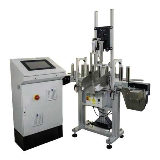
- Page 1 User Manual QCL-MAN -CT2211-Aerosol-Leak-Detection-System, Rev F October 2015 CT2211 Aerosol Leak Detection System...
- Page 2 FK9 4TZ United Kingdom General inquiries about this or other Cascade Technologies products should be sent to [email protected]. If you require technical assistance with this product that is not covered within this user manual, then help can be requested from Cascade Technical Support ([email protected]) or Cascade Technologies distribution partners.
-
Page 3: Table Of Contents
Errors ....................... 24 5.2.1 Overall system healthy ..............24 5.2.2 Leak detector (CT2211) system healthy ........25 5.2.3 Leak detector (CT2211) laser healthy ........... 25 5.2.4 Can lost ..................25 ... - Page 4 Table of Contents User Manual October 2015 QCL-MAN- CT2211-Aerosol-Leak-Detection-System-Rev F 6.1.3 Monthly ................31 Analysis system .................... 31 Venturi ....................... 32 Replacement parts ..................32 Section 7: Troubleshooting and Diagnostics ............... 33 ...
- Page 5 User Manual List of Tables QCL-MAN -CT2211-Aerosol-Leak-Detection-System-Rev F October 2015 List of Tables Table 1-1 Leak detection system specifications ............ 7 Table 5-1 IO lines ....................28 Table 6-1 Aerosol leak detection system replacement parts list ......32 ...
- Page 6 Program Page screen ................. 17 Figure 5-4 Error Status screen ................18 Figure 5-5 CT2211 Main Screen ................19 Figure 5-6 CT2211 Graphs Screen ............... 20 Figure 5-7 Digital IO Status screen ..............21 ...
-
Page 7: Introduction
Leak Detection System Installation and Service Manual. Additional help can also be requested from Cascade Technical Support ([email protected]) or Cascade Technologies distribution partners. Qualified personnel These operating instructions have been prepared for technically qualified personnel who have been specially trained or who possess appropriate knowledge in the field of instrumentation and control. -
Page 8: Certifications And Approvals
Introduction User Manual October 2015 QCL-MAN-CT2211-Aerosol-Leak-Detection-System-Rev F Use of controls or adjustments or performance of procedures other than those specified herein may result in hazardous radiation exposure. All lasers used within the leak detection system are of class 1. The emitted laser light is invisible (mid-infrared) and the pulse duration so short that the unprotected eye will not be damaged. -
Page 9: Aerosol Leak Detection System - Venturi Configuration
E. Encoder signal F. Rejected can signal G. Output gate signal H. Reject signal CT2211 comms (cat5) CT2211 I/O and power K. Mirror cleaning signal L. Air status signal M. Input gate signal Line direction N. Compressed air supply min 5 BAR, max 10 BAR (customer supplied) Max cable run O. -
Page 10: Aerosol Leak Detection System - Blower Configuration
S. Micro Leak detector H. Reject signal T. Air status air control CT2211 communications (cat5) U. Input gate CT2211 I/O and power V. ATEX zone 2 disconnect switch Mirror cleaning signal W. ATEX zone 2 rated blower Air status signal X. -
Page 11: Leak Detector Overview
User Manual Introduction QCL-MAN -CT2211-Aerosol-Leak-Detection-System-Rev F October 2015 Leak detector overview The leak detector identifies aerosol cans that are leaking propellant as they are carried along a conveyor belt at high speed. The leak detector consists of an air extraction arch, air filter/regulator, sample cell, sensor head and either a Venturi or 3-phase blower. - Page 12 Introduction User Manual October 2015 QCL-MAN-CT2211-Aerosol-Leak-Detection-System-Rev F The power supply (not shown) for the sensor is also mounted outside the explosive environment. The Venturi (not shown) is powered by compressed air and mounted in the exhaust line below the sample cell. It is used to draw air from around the aerosol cans via the air extraction arch.
-
Page 13: Detailed System Specification
User Manual Introduction QCL-MAN -CT2211-Aerosol-Leak-Detection-System-Rev F October 2015 Detailed system specification The following table shows the general characteristics of the leak detection system. Table 1-1 Leak detection system specifications Application Leak detection system Measurement technique IR absorption spectroscopy IR source... -
Page 14: System Connection
System Connection User Manual October 2015 QCL-MAN-CT2211-Aerosol-Leak-Detection-System-Rev F 2 System Connection The diagram below shows the electrical connections of the aerosol leak detection system: Figure 2-1 Schematic of I/O and external connections System I/O, External Component Connection and Customer Interface ... -
Page 15: Filter Assembly And Archway Quick Connector
User Manual System Connection QCL-MAN -CT2211-Aerosol-Leak-Detection-System-Rev F October 2015 The air arch is connected to the leak detector using the attached quick fit connector: Figure 2-2 Filter assembly and archway quick connector A. Filter assembly B. Air arch C. Leak detector quick fit connector... -
Page 16: Air Preparation Plate
System Connection User Manual October 2015 QCL-MAN-CT2211-Aerosol-Leak-Detection-System-Rev F The filter regulator, pressure switch, and valve shown below are mounted onto the leak detector pedestal stand. Figure 2-3 Air preparation plate A. Filter regulator B. Pressure switch C. Valve D. Water separator... -
Page 17: Left: Sensor Head, Right: Air Extraction Arch Assembly
User Manual System Connection QCL-MAN -CT2211-Aerosol-Leak-Detection-System-Rev F October 2015 The leak detector is comprised of the following components: Figure 2-4 Left: Sensor head, Right: Air extraction arch assembly A. Sensor head unit B. Air extraction arch System Connection... -
Page 18: System Startup
System Startup User Manual October 2015 QCL-MAN-CT2211-Aerosol-Leak-Detection-System-Rev F 3 System Startup The aerosol leak detection system must be installed and fully commissioned prior to customer operation. Ensure that all cables are correctly terminated and the components on the production line are correctly mounted. The control console must also be securely mounted with clear access around. -
Page 19: Control System Display
User Manual System Startup QCL-MAN -CT2211-Aerosol-Leak-Detection-System-Rev F October 2015 The Micro Leak Control System initialization takes approximately two minutes after power is applied. Figure 3-2 Control system display The message box at the bottom of the screen indicates any errors or warnings detected during the boot sequence. -
Page 20: Shutdown
Shutdown User Manual October 2015 QCL-MAN-CT2211-Aerosol-Leak-Detection-System-Rev F 4 Shutdown There are three system shutdown methods: 150 ms signal from the System I/O line to the PLC line Press the control system Power button on the Home screen. Turn off the Isolation switch on the Control System front panel. -
Page 21: Section 5: Operation
User Manual Operation QCL-MAN -CT2211-Aerosol-Leak-Detection-System-Rev F October 2015 5 Operation The aerosol leak detection system is designed to run autonomously with minimal user interaction required. The majority of the information on screen is for user information only. Some parts of the software require password access; this is described in the relevant sections. -
Page 22: User Login Screen
Operation User Manual October 2015 QCL-MAN-CT2211-Aerosol-Leak-Detection-System-Rev F page. Reset can buffer button: resets the cans in Message box arrows: used to scroll up and the can buffer to 0. down through the messages in the message box. Message box: displays messages, warnings, Error status indicator: shows the current and errors for the control system. -
Page 23: Program Page
User Manual Operation QCL-MAN -CT2211-Aerosol-Leak-Detection-System-Rev F October 2015 5.1.3 Program Page The programs used by the control system store the parameters required by the control system that are variable between different can diameters and products. for a description of the creation and use of Section 5.4: Control system programs... -
Page 24: Error Status Page
Operation User Manual October 2015 QCL-MAN-CT2211-Aerosol-Leak-Detection-System-Rev F 5.1.4 Error Status screen This screen displays the current state of the control system. It allows the user to reset any errors once they have cleared. All error signals must be acknowledged by pressing the reset errors button. -
Page 25: Ct2211 Main Screen
CT2211 IN Counter: provides a running count of cans entering the detection zone since last reset. CT2211 OUT Counter: provides a running count of cans exiting the detection zone since last reset. -
Page 26: Ct2211 Graphs Screen
Figure 5-6 below shows the CT2211 Graphs Screen. Figure 5-6 CT2211 Graphs Screen Laser Pulse Graph: displays a laser pulse from the last second of running. -
Page 27: Digital Io Status Page
User Manual Operation QCL-MAN -CT2211-Aerosol-Leak-Detection-System-Rev F October 2015 5.1.7 Digital IO Status screen This page allows the operator to see in real time the state of any of the digital IO lines to the control system. For some signals that are rapidly changing, the signal change on screen may be too quick to observe. -
Page 28: Optical Gates Page
Operation User Manual October 2015 QCL-MAN-CT2211-Aerosol-Leak-Detection-System-Rev F 5.1.8 Optical Gates screen The Optical Gates screen allows the user to see the output gate position and the bin full time for the control system. below shows the Optical Gates screen: Figure 5-8 Figure 5-8 Optical Gates page Input Gate Position: displays the position in mm of the input gate of the system. -
Page 29: Rejector Page
User Manual Operation QCL-MAN -CT2211-Aerosol-Leak-Detection-System-Rev F October 2015 5.1.9 Rejector screen The rejector is used by the control system to remove faulty containers from the production line. There are a number of different options for the rejector. This manual assumes that the default air rejector is being used. -
Page 30: Line Speed Page
Operation User Manual October 2015 QCL-MAN-CT2211-Aerosol-Leak-Detection-System-Rev F 5.1.10 Line Speed screen This page shows the line speed of the conveyor. Figure 5-10 below shows the Line Speed screen. Figure 5-10 Line Speed screen Encoder Description: describes the use of the encoder. -
Page 31: Leak Detector (Ct2211) System Healthy
Operation QCL-MAN -CT2211-Aerosol-Leak-Detection-System-Rev F October 2015 5.2.2 Leak detector (CT2211) system healthy The leak detector provides the control system with a healthy status signal. If this signal becomes too low, it will trigger this error. See Section 7: Troubleshooting and Diagnostics for more information on this error. -
Page 32: Reject Verification
Operation User Manual October 2015 QCL-MAN-CT2211-Aerosol-Leak-Detection-System-Rev F 5.2.7 Reject verification When the rejector removes a can from the line, the reject verification gate expects to see a trigger with in a set time after the rejector is activated. If the reject verification gate does not see this trigger, the reject verification error is triggered. -
Page 33: Repeatable Reject Error
Compressed air error The compressed air error reports when insufficient pressure on the Venturi/reject/purge air is detected. Insufficient air pressure results in decreased performance of the CT2211 aerosol leak detection system. 5.2.15 Error flags 14/15 These error flags are currently unassigned. -
Page 34: Linestop (In)
Operation User Manual October 2015 QCL-MAN-CT2211-Aerosol-Leak-Detection-System-Rev F Table 5-1 IO lines Terminal Line description System input/output See Section number : number : Linestop Input 5.3.1 Shutdown system Input 5.3.2 Spare Input Spare Input Spare Input Return Input Linestop 1 Output 5.3.3... -
Page 35: Control System Programs
User Manual Operation QCL-MAN -CT2211-Aerosol-Leak-Detection-System-Rev F October 2015 Control system programs The aerosol leak detection system loads parameters from a number of different sources. One of those sources is the program file. The parameters loaded from the program file are:... -
Page 36: Add Programs
Operation User Manual October 2015 QCL-MAN-CT2211-Aerosol-Leak-Detection-System-Rev F The different programs allow the user to customize the operation of the control systm for different can types and diameters. The program can also be backed up by selecting the down arrow to the left of the Program Selector as seen in Figure 5-12 Program Page. -
Page 37: Maintenance
User Manual Maintenance QCL-MAN -CT2211-Aerosol-Leak-Detection-System-Rev F October 2015 6 Maintenance The aerosol leak detection system is inherently reliable, reducing the requirement for routine maintenance. This section provides information on the schedule of maintenance to be performed by the user in order to ensure the reliable performance of the system. -
Page 38: Venturi
Maintenance User Manual October 2015 QCL-MAN-CT2211-Aerosol-Leak-Detection-System-Rev F Venturi The Venturi should require no maintenance other than periodic exterior cleaning to remove surface dust. Replacement parts The following parts are available from Cascade as replacement parts for the leak detection system:... -
Page 39: Troubleshooting And Diagnostics
User Manual Troubleshooting and Diagnostics QCL-MAN -CT2211-Aerosol-Leak-Detection-System-Rev F October 2015 7 Troubleshooting and Diagnostics The aerosol leak detection system is designed to run unattended and to recover from system issues where possible. This chapter is designed to assist you in the identification and solution of potential problems. -
Page 40: Network Status
Troubleshooting and Diagnostics User Manual October 2015 QCL-MAN-CT2211-Aerosol-Leak-Detection-System-Rev F Figure 7-1 Network status Network status lamps Figure 7-2 12V PSU status 12V PSU status lamp Troubleshooting and Diagnostics... -
Page 41: Circuit Breaker
User Manual Troubleshooting and Diagnostics QCL-MAN -CT2211-Aerosol-Leak-Detection-System-Rev F October 2015 Figure 7-3 Circuit breaker Circuit breaker Troubleshooting and Diagnostics... - Page 42 ©2015 Emerson Process Management. All rights reserved. The Emerson logo is a trademark and service mark of Emerson Electric Co. All other marks are property of their respective owners. The contents of this publication are presented for information purposes only, and, while effort has been made to ensure their accuracy, they are not to be construed as warranties or guarantees, express or implied, regarding the products or services described herein or their use or applicability.