Table of Contents
Quick Links
Table of Contents

Related Manuals for Advantech B+B SMARTWORX SmartStart SL302


Summary of Contents for Advantech B+B SMARTWORX SmartStart SL302
- Page 1 LTE Industrial Router SmartStart SL302 USER’S MANUAL...
- Page 2 2016 Advantech B+B SmartWorx s.r.o. No part of this publication may be reproduced or transmitted in any form or by any means, electronic or mechanical, including photography, recording, or any information storage and retrieval system without written consent. Information in this manual is subject to change without notice, and does not represent a commitment on the part of Advantech B+B SmartWorx.
- Page 3 GPL licence Source codes under GPL licence are available free of charge by sending an email to: [email protected]. Advantech B+B SmartWorx s.r.o., Sokolska 71, 562 04 Usti nad Orlici, Czech Republic Manual Rev. 1 released in CZ, July 20, 2016...
-
Page 4: Table Of Contents
CONTENTS Contents 1 Safety Instruction 2 WEEE directive 3 Router Description 3.1 LTE Category 1 (Cat.1) ....... 3.2 Basic HW Information . - Page 5 CONTENTS 7.2 Technical specification of user interfaces ..... . 7.3 Standards and Regulations ......7.4 Type Tests and Environmental Conditions .
- Page 6 LIST OF FIGURES List of Figures Access to the Internet from LAN ......Backed up access to the Internet .
- Page 7 LIST OF TABLES List of Tables Router versions ........Delivery identification .
-
Page 8: Safety Instruction
1. SAFETY INSTRUCTION 1. Safety Instruction Please, observe the following instructions: The router must be used in compliance with all applicable international and national laws and in compliance with any special restrictions regulating the utilization of the router in prescribed applications and environments. To prevent possible injury and damage to appliances and to ensure compliance with all relevant provisions, use only the original accessories. -
Page 9: Weee Directive
2. WEEE DIRECTIVE 2. Product Disposal Instructions The WEEE (Waste Electrical and Electronic Equipment: 2002/96/EC) directive has been introduced to ensure that electrical/electronic products are recycled using the best available recovery techniques to minimize the impact on the environment. This product contains high quality materials and components which can be recycled. -
Page 10: Router Description
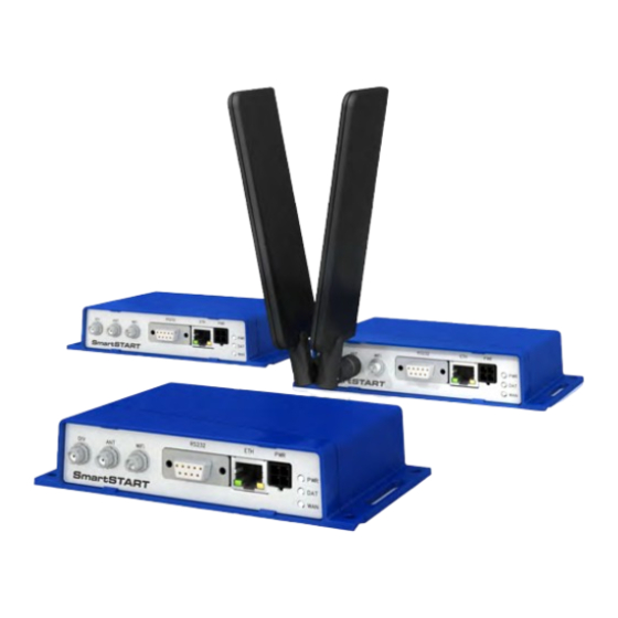
3. ROUTER DESCRIPTION 3. Router Description Cellular router SmartStart SL302 is designed for wireless communication in the mobile networks that make use of traditional cellular technologies. The primary purpose of this router is its use in the newest Category 1 (Cat.1) services on the cellular LTE network of the AT&T carrier. -
Page 11: Usage Of The Router
3. ROUTER DESCRIPTION The router also supports additional software like R-SeeNet for permanent traffic monitoring of routers. Examples of possible applications mobile office telematic smart meters for utilities telemetric fleet management remote monitoring security system vending and dispatcher machines 3.4 Usage of the Router The router is primarily intended for these four basic situations: I. -
Page 12: Backed Up Access To The Internet
3. ROUTER DESCRIPTION II. Backed up access to the Internet (from LAN) Figure 2: Backed up access to the Internet III. Secure networks interconnection or using VPN Figure 3: Using VPN tunnel... -
Page 13: Serial Gateway
3. ROUTER DESCRIPTION IV. Serial Gateway Figure 4: Serial Gateway... -
Page 14: Contents Of Package
4. CONTENTS OF PACKAGE 4. Contents of Package The basic router set available for delivery includes the following items: router, power supply and IO cable (1.5 m long), clip for the DIN rail (two screws are included), paper start guide. Figure 5: Contents of package 4.1 Recommended Accessories The following list contains the recommended accessories. -
Page 15: Router Design
5. ROUTER DESIGN 5. Router Design 5.1 Router Versions The SmartStart router is supplied in the following versions (see table below). All versions are available only in the plastic box. Router versions SL302 with RS232 SL302 with RS232 & WiFi Table 1: Router versions Figure 6: Front panel... -
Page 16: Delivery Identification
5. ROUTER DESIGN 5.2 Delivery Identification Trade name Product name Other SL302 SmartStart LTE router (Cat.1) for NAM (AT&T) Table 2: Delivery identification Figure 7: Label for versions without WiFi Figure 8: Label for versions with WiFi 5.3 Order Codes Order codes overview is shown in the table below. -
Page 17: Basic Dimensions Of The Router Box
5. ROUTER DESIGN 5.4 Basic Dimensions of the Router Box Figure 9: Basic dimensions of the router box... -
Page 18: Mounting Recommendations
5. ROUTER DESIGN 5.5 Mounting Recommendations possibility to be put on a work surface, DIN rail EN 60715 with included clip CKD-SBD23. For the most of applications with a built-in router in a switch board it is possible to recognize two kinds of environments: no public and industry environment of low voltage with high interference, public environment of low voltage without high interference. -
Page 19: Removing From The Din Rail
5. ROUTER DESIGN 5.6 Removing from the DIN Rail DIN holder is suitable for DIN rail according to EN 60715 standard only. Default position of CKD-SBD23 holder, which is used for mounting the router on a DIN rail, is shown in the following figure: Figure 10: Default position of DIN holder For removing from the DIN rail it is necessary to lightly push upward the router so that the... -
Page 20: Description Of The Rear Panel
5. ROUTER DESIGN 5.7 Description of the Rear Panel The rear panel contains two holders for SIM cards (SIM1, SIM2) and RST button used to restore default configuration and reboot the router. 5.8 Description of the Front Panel On the front panel is the following: Caption Connector Description... -
Page 21: Status Indication
5. ROUTER DESIGN 5.8.1 Status indication About router status inform three LED indicators on the front panel. The ETH port has two additional LEDs that provide information about the port status. Caption Color State Description Green Blinking Router is ready Starting of the router Fast blinking Updating firmware... -
Page 22: Power Pwr / Io Connector
5. ROUTER DESIGN 5.8.2 Power PWR / IO Connector Panel socket 4-pin. Pin number Signal mark Description GND(-) Negative pole of DC supply voltage VCC(+) Positive pole of DC supply voltage (+9 to +36 V DC) Binary input OUT0 Binary output Table 6: Connection of PWR / IO connector Figure 13: PWR / IO connector Power supply for the router must be between +9 V to +36 V DC supply. -
Page 23: Characteristics Of Binary Input
5. ROUTER DESIGN The PWR / IO interface is also designed for processing of binary input and control (setting) binary output. Binary Input logical 0 / 1 Voltage Web interface status logic 0 0 – 0.7 V logic 1 1.6 – 36 V Table 7: Characteristics of binary input The binary input status in the Shell returned via io get bin0. -
Page 24: Antenna Connector Ant, Div And Wifi
5. ROUTER DESIGN 5.8.3 Antenna Connector ANT, DIV and WiFi Main and diversity antennas are connected to the router using the SMA connector on the front panel. There is also available R-SMA antenna connector through which the additional antenna can be connected, if the router is equipped with WiFi module. ANT connector is used to connect the main antenna router. -
Page 25: Sim Card Reader
5. ROUTER DESIGN 5.8.4 SIM Card Reader SmartStart SL302 contains two readers for 3 V and 1.8 V SIM cards, which are placed on the rear panel of the device. For getting the router to work is necessary to insert an activated SIM card with an unblocked PIN code. -
Page 26: Ethernet Port Eth
5. ROUTER DESIGN 5.8.5 Ethernet Port ETH The panel socket RJ45 is used for this interface. Ethernet isolation is 1500 V. Signal mark Description Data flow direction TXD+ Transmit Data – positive pole Input/Output TXD- Transmit Data – negative pole Input/Output RXD+ Receive Data –... -
Page 27: Serial Port Rs232
5. ROUTER DESIGN 5.8.6 Serial Port RS232 The DB9 Female connector is used for this interface. Signal mark Description Data flow direction Data Carrier Detect Output Receive Data Output Transmit Data Input Data Terminal Ready Input System Ground — Data Set Ready Output Request to Send Input... -
Page 28: Reset
5. ROUTER DESIGN 5.8.7 Reset When PWR LED starts flashing on the front panel, it is possible to restore the default con- figuration of the router by pressing the RST button on the rear panel. After pressing this button the default configuration is restored and then router reboots (green LED will be on). For pressing the RST button could be used a narrow screwdriver. -
Page 29: First Use
6. FIRST USE 6. First Use 6.1 Connecting the Router Before the First Use Before putting the router into operation it is necessary to connect all components which are required to run your applications. Don’t forget to insert SIM card. The router can not operate without connected antenna, SIM card and power supply. -
Page 30: Start
6. FIRST USE 6.2 Start The router is put into operation when the power supply is connected to this router. By default, the router will automatically start to log on to the default APN. DHCP server will start to assign addresses for devices on the Ethernet port ETH. Router behavior can be changed via the web interface. -
Page 31: Router Web Interface
6. FIRST USE After successfully entering login information user gains access to the router via his internet browser. Figure 24: Router web interface A detailed description of the router settings via the Web interface can be found in the document Configuration manual. -
Page 32: Technical Parameters
7. TECHNICAL PARAMETERS 7. Technical Parameters 7.1 Basic Parameters SmartStart Temperature range Operating -40 C to +75 C Storage -40 C to +85 C Humidity Operating 0 to 95 % relative humidity non condensing Storage 0 to 95 % relative humidity non condensing Altitude Operating 2000 m / 70 kPa... -
Page 33: Standards And Regulations
7. TECHNICAL PARAMETERS 7.3 Standards and Regulations The router complies with the following standards and regulations. Standards and regulations ETSI EN 301 489-1 v1.9.2, IEC 61000-6-2:2005, IEC 61000-6-3:2006 Safety EN 60950-1:2006 + A11:2009 + A1:2010 + A12:2011 + A2:2013, EN 62311:2008 REACH and RoHS compliant Table 13: Standards and regulations 7.4 Type Tests and Environmental Conditions... -
Page 34: Technical Parameters Of Module
7. TECHNICAL PARAMETERS 7.5 Technical Parameters of Module LTE module for NAM – AT&T LTE parameters Bit rate 10 Mbps (DL) / 5 Mbps (UL) LTE FDD Cat.1, 3GPP release 9 compliant Supported bandwidths: 5 Mhz, 10 Mhz, 20 Mhz Supported frequencies: 700 / 850 / 1700(AWS) / 1900 MHz UMTS parameters Bit rate 384 kbit/s (DL) / 384 kbit/s (UL) -
Page 35: Other Technical Parameters
7. TECHNICAL PARAMETERS 7.7 Other Technical Parameters Other technical parameters CPU power 2 DMIPS per MHz Flash memory 256 MB 512 MB M-RAM 128 kB Table 17: Other technical parameters... -
Page 36: Recommended Literature
8. RECOMMENDED LITERATURE 8. Recommended Literature Advantech B+B SmartWorx: Start Guide for SmartStart, Advantech B+B SmartWorx: SmartStart Configuration Manual, Advantech B+B SmartWorx: Commands and Scripts. -
Page 37: Troubleshooting
9. TROUBLESHOOTING 9. Troubleshooting If you can not connect to the router from your PC, your network card may be configured the way it is not possible to connect to the router. Take one or more of the following steps to solve the problem: Select the communication rate 10 MB/s in the properties of your network card. - Page 38 9. TROUBLESHOOTING Ethernet connection fails or isn’t establishing. It is possible to turn auto negotiation off and set a rate and duplex manually on the Ethernet interface of the router. DynDNS doesn’t function. With private APN this is not functional. If the same IP address is recorded in your canonic name as dynamically assigned address, it means that the operator is using NAT or firewall.
-
Page 39: Customers Support
Consult the dealer or an experienced radio/TV technician for help. Important: Changes or modifications to this product not authorized by Advantech B+B SmartWorx could void the electromagnetic compatibility (EMC) and wireless compliance and negate your authority to operate the product. This product has demonstrated EMC compliance under conditions that included the use of compliant peripheral devices and shielded cables between system components. -
Page 40: Customer Support For Nam
10. CUSTOMERS SUPPORT 10.2 Customer Support for NAM Up to date product information is on the website: www.bb-smartworx.com For Technical Support: Call 815-433-5100...