Available languages
Available languages
Quick Links
Arize Element
Horticulture LED Lighting System
Installationsvejledning
DA
Einbauanleitung
DE
Guía de instalación
ES
220-240V
380-415V
50-60Hz
50-60Hz
RISK OF ELECTRIC SHOCK
• Turn power off before inspection, installation or removal.
• Properly ground electrical enclosure.
RISK OF FIRE
• Follow all IEC and local building codes.
• Use only IEC approved wire for input/output connections.
Minimum size 3G 0.75mm
.
2
• Minimum 300mm distance from light module & driver to any
combustible material.
• Minimum 150mm clearance between light module & driver, light
module & light module, driver & driver.
• The light module shall be installed lens down with a minimum of
130mm to anything below.
The LED luminaire must be connected to
the mains supply according to its ratings on
the product label.
CAUTION
• Do not operate the product with damaged parts.
• Turn off power before inspection, installation or removal.
• Luminaire may fall down if not installed properly.
• Wear work gloves to prevent dirt and oil from being transferred to
the luminaire.
• Not for direct exposure to the weather.
• To ensure the product warranty is valid, please ensure all installation
instructions and environmental conditions for storage and operation
are complied with.
• The light source of this luminaire is not replaceable; when the light
source reaches its end of life the whole luminaire shall be replaced.
• Use only in the manner intended by the manufacturer. If you have
any questions, contact the manufacturer.
• For safe operation, and to maximize the longevity of the luminaire;
ensure that the light module and driver are clean and free of dirt,
dust, oil, or any other debris.
• Do not apply any kind of film on the lens or otherwise cover the
driver or light engine in any way.
• The external flexible cable or cord of this luminaire cannot be
replaced; if the cord is damaged, the luminaire shall be destroyed.
®
L1000 Gen2
Asennusohje
FI
IT
Guide d'installation
FR
LT
Felszerelési útmutató
HU
NL
IP66
Guida all'installazione
Monteringsanvisning
NO
Sumontavimo vadovas
Instrukcja instalacji
PL
Installatiehandleiding
Guia de Instalação
PT
WARNING
220–240 VAC
Part Number
Power (W)
GEHE-HPPRB2A
585
GEHE-HPPBB2A
622
GEHE-HPKTB2A
606
GEHE-HPKRB2A
623
GEHE-HPKBB2A
639
GEHE-HPKFB2A
643
GEHE-HBRIB2A
656
GEHE-HBRVB2A
681
GEHE-VPPRB2A
530
GEHE-VPPBB2A
575
GEHE-VPKTB2A
538
GEHE-VPKRB2A
569
GEHE-VPKBB2A
590
GEHE-VPKFB2A
570
Suitable for operation in an ambient temperature
between 0°C and 40°C.
40°C
A mechanical ventilation or cooling system is
required to maintain the temperature within the
0°C
growing space below 40°C when the light module
is in operation.
HORT162 | DOC-xxxxxxx
Installationsguide
SE
IEC/TR 62778 Risk Group 2 (RG2)
380–415 VAC
Risk
Power (W)
Group
589
2
626
2
610
2
628
2
643
2
647
2
660
2
684
2
533
2
580
2
542
2
573
2
594
2
575
2
Min. Viewing
Distance (m)
5.2
5.2
5.2
5.2
5.2
5.2
5.2
5.2
5.2
5.2
5.2
5.2
5.2
5.2

Related Manuals for GE Arize Element L1000 Gen2


Summary of Contents for GE Arize Element L1000 Gen2
- Page 1 HORT162 | DOC-xxxxxxx ® Arize Element L1000 Gen2 Horticulture LED Lighting System Installationsvejledning Asennusohje Guida all’installazione Monteringsanvisning Installationsguide Einbauanleitung Guide d’installation Sumontavimo vadovas Instrukcja instalacji Guía de instalación Felszerelési útmutató Installatiehandleiding Guia de Instalação 220-240V 380-415V IP66 50-60Hz 50-60Hz WARNING RISK OF ELECTRIC SHOCK •...
-
Page 2: Driver Specifications
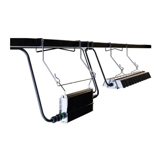
® Arize Element L1000 Gen2 Installation Guide System Component Parts Please refer to order logic to determine included or accessory AC cable Driver Driver Bracket Hanger (2x) Light Module Brackets (2x) Light Module Light Module Specifications System Input Current [A] System Input Current [A] Low Voltage Driver High Voltage Driver... - Page 3 ® Arize Element L1000 Gen2 Installation Guide Interconnection Cable Specifications Description Detailed Description GECA60D16-OL04B AC Leader Cable, 1219 mm, CE GECA60FNA-NL00B AC Field Installable Connector, UL and CE (Wieland P.N. 96.031.4155.7) GECA30G14-EN03B DC Inter-Connection Cable, 914 mm, UL and CE GECA30G14-EN06B DC Inter-Connection Cable, 1828 mm, UL and CE GECA30H20-OO03B...
- Page 4 ® Arize Element L1000 Gen2 Installation Guide 1 Installation of the Light Module 1.1 Installation of Module Brackets If not preassembled, install light module brackets on light module. Install brackets at location A. Slide down bracket along channels. SNAP! SNAP! Press down on bracket until hooks snap into place.
- Page 5 ® Arize Element L1000 Gen2 Installation Guide 1.2 Selection of Mounting Hardware Based on the cross section of the structural member select the correct hanger or mounting cable. Unistrut 41 mm Square 70 mm Other Structural Members Use standard hanger 41 mm Use standard hanger 70 mm Use 0.5 m or 1.5 m universal cable Offset hanger 41 mm...
-
Page 6: Tools Required
® Arize Element L1000 Gen2 Installation Guide 1.4 Installation with Universal Cables Loop Hook Wrap loop end of cable over structural member. Attach hooks to light module brackets. Ensure hook gate is closed. Insert hook through loop end. 1.5 Installation with Perpendicular 90° Universal Mounting Kit Kits Contents (SKU: 93139057) 1x Worm Drive Clamp 1828 mm Inter-connection... - Page 7 ® Arize Element L1000 Gen2 Installation Guide Installation Steps for Perpendicular 90° Universal Mounting Kit First determine which 2 slots on Place the metal bracket on Secure the metal bracket on the metal bracket most closely top of the structural member to the top of the structural correspond to the structural and wrap the strap around...
-
Page 8: Installation Of The Driver
® Arize Element L1000 Gen2 Installation Guide 2 Installation of the Driver 2.1 Installation of Driver Bracket If not preassembled, install driver bracket onto driver. Bracket Orient driver perpendicular to the bracket. Ensure first end of bracket hook is lined up with oval mounting hole of driver. - Page 9 ® Arize Element L1000 Gen2 Installation Guide 2.2 Selection of Mounting Hardware Based on the cross section of the structural member select the correct hanger or mounting cable. Unistrut 41 mm Square 70 mm Other Structural Members Use standard hanger 41 mm Use standard hanger 70 mm Use 0.5 m universal cable Offset hanger 41 mm...
- Page 10 ® Arize Element L1000 Gen2 Installation Guide 2.4 Installation with Universal Cables Loop Hook Wrap loop end of cable over structural member. Attach hooks to oval driver mounting holes. Ensure hook gate is closed. Insert hook through loop end. 2.5 Installation with Custom Brackets If you choose to use your own custom mounting method, attach to oval driver mounting...
-
Page 11: Electrical Connections
® Arize Element L1000 Gen2 Installation Guide 3 Electrical Connections WARNING RISK OF ELECTRIC SHOCK Turn power OFF before inspection, installation or removal. Dimming DC Output AC Input Driver connections 3.1 Connect the Driver Output to Light Module CLICK! Align keying features of Push connectors together until Recommended: secure light larger output connector on... - Page 12 ® Arize Element L1000 Gen2 Installation Guide 3.2.1 Connect the Driver Input CLICK! Align keying features on driver Push connectors together until Secure AC input leader cable, with connector on the selected a click is heard. away from driver and light leader cable.
- Page 13 ® Arize Element L1000 Gen2 Installation Guide 3.3 Connection Schematic Use proper circuit protection level 3-Phase ∆ 3-Phase Y AC line Driver Input Wire Colors Brown = Line 1 Blue = Neutral or Line 2 Driver Driver Driver Driver Driver Driver Yellow/Green = Ground REPEAT FOR ENTIRE CIRCUIT BALANCING OUT EACH PHASE *Blue = Neutral or Line 2...
- Page 14 ® Arize Element L1000 Gen2 Installation Guide 2 Installation af driver ADVARSEL 2.1 Installation af driverbeslag RISIKO FOR ELEKTRISK STØD Hvis det ikke er monteret på forhånd, skal du installere driverbeslaget på driveren. Sluk for strømmen inden kontrol, montering eller afmontering. •...
- Page 15 ® Arize Element L1000 Gen2 Installation Guide WARNUNG 2 Installation des Treibers STROMSCHLAGGEFAHR 2.1 Installation der Treiberkonsole Schalten Sie die Stromversorgung vor der Inspektion, Installation oder Entfernung des Falls nicht vormontiert, Treiberkonsole am Treiber anbringen. • Geräts aus. Richten Sie den Treiber senkrecht zur Konsole aus. Erden Sie das Elektrogehäuse ordnungsgemäß.
- Page 16 ® Arize Element L1000 Gen2 Installation Guide ATENCIÓN 2 Instalación del conductor RIESGO DE DESCARGA ELÉCTRICA 2.1 Instalación del soporte del conductor Apague el suministro eléctrico antes de inspeccionarlo, instalarlo o retirarlo. Si no se han montado previamente, instale el soporte del conductor en el conductor. •...
- Page 17 ® Arize Element L1000 Gen2 Installation Guide 2 Ohjaimen asennus VAROITUS 2.1 Ohjaimen kiinnikkeen asennus SÄHKÖISKUN RISKI Ellei ohjaimen kiinnikettä ole asennettu valmiiksi, asenna se ohjaimeen. Katkaise virta ennen tarkastusta, asennusta tai irrottamista. • Sähkökotelo on maadoitettava asianmukaisesti. Aseta ohjain kohtisuoraan kiinnikkeeseen nähden. •...
- Page 18 ® Arize Element L1000 Gen2 Installation Guide AVERTISSEMENT 2 Installation du driver RISQUE DE CHOC ÉLECTRIQUE 2.1 Installation du support de driver Coupez l’alimentation avant l’inspection, l’installation ou le retrait. S’il n’est pas déjà monté, installez le support du driver sur ce dernier. •...
- Page 19 Az elektromos szekrényt megfelelően földelje! A vezérlőegységet a konzolra merőlegesen kell elhelyezni. • TŰZVESZÉLY Gondoskodjon róla, hogy a konzol akasztójának első vége egy vonalban van a vezérlőegység Az IEC és a helyi építési előírásokat kell követni. ovális rögzítőnyílásával! • A bemeneti/kimeneti csatlakozásokhoz kizárólag IEC által jóváhagyott vezetéket szabad Szorítsa össze a konzol karjait, majd csúsztassa az akasztót a vezérlőegység első...
- Page 20 ® Arize Element L1000 Gen2 Installation Guide AVVERTENZA 2 Installazione del trasformatore 2.1 Installazione della staffa del trasformatore RISCHIO DI SCOSSE ELETTRICHE Prima dell’ispezione, dell’installazione o della rimozione, disattivare l’alimentazione • Se non è preassemblata, installare la staffa del trasformatore sul trasformatore. elettrica.
- Page 21 ® Arize Element L1000 Gen2 Installation Guide ĮSPĖJIMAS 2. Maitinimo šaltinio stabilizatoriaus montavimas ELEKTROS ŠOKO PAVOJUS 2.1. Maitinimo šaltinio stabilizatorius laikiklio montavimas Išjunkite maitinimą prieš apžiūrą, montavimą arba šalinimą. Jei iš anksto nesumontuota, pritvirtinkite maitinimo šaltinio stabilizatoriaus laikiklį prie • Tinkamai įžeminkite elektros įrangos gaubtą.
- Page 22 Laat de driver vrij rechtop slingeren en zorg dat de haken aan beide zijden juist zijn • & driver. ingebracht. The lichtmodule dient te worden geïnstalleerd met de lens naar beneden met daaronder • minstens 130mm vrije ruimte. 2.2 Selectie van montagemateriaal...
- Page 23 ® Arize Element L1000 Gen2 Installation Guide 2 Montering av driveren ADVARSEL 2.1 Montering av driverbrakett FARE FOR ELEKTRISK SJOKK Hvis driverbraketten ikke er forhåndsmontert, må du montere den på driveren. Slå av strømmen før inspeksjon, installering eller fjerning. • Elektrisk kabinett må...
- Page 24 ® Arize Element L1000 Gen2 Installation Guide OSTRZEŻENIE 2 Montaż zasilacza ZAGROŻENIE PORAŻENIEM PRĄDEM ELEKTRYCZNYM 2.1 Montaż uchwytów zasilacza Przed inspekcją, montażem lub demontażem należy zawsze odłączyć zasilanie. Jeżeli nie wykonano wstępnego montażu, to na zasilaczach należy zainstalować uchwyty. • Obudowy elektryczne należy zawsze prawidłowo uziemić.
- Page 25 ® Arize Element L1000 Gen2 Installation Guide AVISO 2 Instalação da fonte de alimentação RISCO DE CHOQUE ELÉTRICO 2.1 Instalação do suporte da fonte de alimentação Desligue o equipamento antes de qualquer inspeção, instalação ou remoção. Se não estiver pré-montado, instale o suporte da fonte de alimentação na fonte de •...
- Page 26 ® Arize Element L1000 Gen2 Installation Guide 2 Installation av medbringaren VARNING 2.1 Installation med medbringarkonsol RISK FÖR ELEKTRISKA STÖTAR Om den inte är förmonterad, montera medbringarkonsolen på medbringaren. Stäng av strömtillförseln före inspektion, installation och borttagning. • Jorda höljet ordentligt. Rikta medbringaren vinkelrätt mot konsolen.
- Page 27 Current Netherlands B.V., Programmeurstraat 6, 1033MT Amsterdam, Netherlands www.gecurrent.com © 2022 Current Lighting Solutions, LLC. All rights reserved. GE and the GE monogram are trademarks of the General Electric Company and are used under license. Information provided is subject to change without notice.