Garmin G1000 Maintenance Manual
Hide thumbs
Also See for G1000:
- Manual (724 pages) ,
- Pilot's manual (708 pages) ,
- System maintenance manual (340 pages)

Related Manuals for Garmin G1000


Summary of Contents for Garmin G1000
- Page 1 G1000 SYSTEM MAINTENANCE MANUAL STANDARD PISTON/TURBOPROP AIRCRAFT 190-00907-00 September 2008 Revision B...
- Page 3 Garmin. Garmin hereby grants permission to download a single copy of this manual and of any revision to this manual onto a hard drive or other electronic storage medium to be viewed and...
- Page 4 Hardware and Software Compatibility Check. 10-10 Added new section 10.9 Installation of OEM specific splash screen procedure. 10-12 Added new section 10.11, Generic SVS Loading Procedure for GDU v9.0x and above. Page 1-2 G1000 System Maintenance Manual Rev. B 190-00903-00...
- Page 5 United States without first obtaining an export license. The preceding statement is required to be included on any and all reproductions in whole or in part of this manual.” G1000 System Maintenance Manual Page i 190-00907-00...
- Page 6 State of California to cause cancer, birth defects, or reproductive harm. This Notice is being provided in accordance with California's Proposition 65. If you have any questions or would like additional information, please refer to the Garmin web site at www.garmin.com/prop65. CAUTION The GDU 1xxx lamps contain mercury and must be recycled or disposed of according to local, state, or federal laws.
-
Page 7: Table Of Contents
GWX 68 Weather Radar................2-7 2.14 GTA 82 Pitch Trim Adapter ................2-8 SECTION 3—SYSTEM OVERVIEW G1000 Flight Instrumentation ............... 3-2 G1000 Engine Indication System ..............3-3 G1000 Communication and Navigation System........... 3-4 GFC 700 Autopilot ..................3-5 G1000 System Maintenance Manual Page iii 190-00907-00 Rev. - Page 8 ______________________________________________________________ SECTION 4—CONFIGURATION MODE Introduction....................4-1 G1000 Operation ..................4-2 Configuration Page Groups and Pages............4-2 Secure Digital (SD) Cards ................4-4 'SET' and 'ACTIVE' Commands ..............4-5 Configuration Status ..................4-6 Data Transmission Indicators ............... 4-6 SECTION 5—TROUBLESHOOTING System Annunciations .................. 5-1 Messages and Annunciations ..............
- Page 9 Recommended Tools ................... 9-1 General Maintenance Procedures..............9-2 GFC Visual Inspection Procedure ..............9-2 GSA Greasing Procedure................9-3 GDC RVSM Altitude Inspection..............9-3 Category B Long Term Power Interrupt Inspection ........9-4 G1000 System Maintenance Manual Page v 190-00907-00 Rev. B...
- Page 10 Hardware and Software Compatibility Check ..........10-1 10.2 Configuration File Overview ............... 10-1 10.3 Initial Software and Configuration Overview..........10-3 10.4 G1000 Software and Configuration Upload..........10-4 10.5 Final Configuration Items ................10-6 10.6 Software/Configuration Troubleshooting ............ 10-7 10.7 System Communication Hierarchy ............. 10-8 10.8...
- Page 11 Basic G1000 System ..................3-1 Basic G1000 Flight Instrumentation ............. 3-2 Basic G1000 Engine Indication System ............3-3 Basic G1000 Communication and Navigation System ......... 3-4 Basic GFC 700 Autopilot System ..............3-5 System Status Page (Configuration Mode) ..........4-1 G1000 Softkeys ....................
- Page 12 GEA Backshell Thermocouple ..............6-7 Non-WAAS (GIA 63) System Status Page ........... 7-2 WAAS (GIA 63) System Status Page............7-2 G1000 Normal Mode Check ................. 7-6 G1000 Reversionary Mode Check ............... 7-6 AUX-GPS Status Page (example).............. 7-11 Marker Beacon Symbology ................ 7-14 Pitch/Roll Offset..................
- Page 13 ______________________________________________________________ TABLES Configuration Page Groups (example only) ..........4-3 GRS 77/GMU 44 Calibration ..............7-17 GDC 74B RVSM Altitude Inspection Criteria..........9-3 G1000 System Maintenance Manual Page ix 190-00907-00 Rev. B...
- Page 14 ______________________________________________________________ Blank Page Page x G1000 System Maintenance Manual Rev. B 190-00907-00...
-
Page 15: Section 1-Introduction
This manual presumes familiarity with the basic operating procedures covered in the G1000 Pilot's Guide and Cockpit Reference Guide (CRG). The G1000 can be configured using two or three displays. This manual describes a two display system. - Page 16 _________________________________________________________________ Section 10―System Reconfiguration This section explains how to completely reconfigure the system should it become necessary. Appendix A―Connector Pin Assignments This appendix illustrates and lists the names of G1000 connector pins. Page 1-2 G1000 System Maintenance Manual Rev. B...
-
Page 17: Section 2-Lru Descriptions
SECTION 2 LRU DESCRIPTIONS This section describes the Line Replaceable Units (LRUs) that could be configured in a G1000 for piston and turboprop aircraft. Not all of the LRUs described in this section are necessarily standard equipment, some are optional depending on the specific model of aircraft. Refer to OEM maintenance documentation for the exact quantity of LRUs used in a specific installation. -
Page 18: Gma 1347(X) Audio Panel
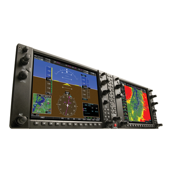
_________________________________________________________________ The GDU 1xxx is the most visible portion of the G1000. In a two display installation, one GDU is configured as a Primary Flight Display (PFD), the other is configured as the Multi-Function Display (MFD). The MFD displays navigation information and engine/airframe instrumentation. The PFD displays primary flight information in place of traditional gyro systems. -
Page 19: Gdc 74(X) Air Data Computer
_________________________________________________________________ The GIA is the central ‘Integrated Avionics Unit’ (IAU) to the G1000 system. The GIA functions as a main communications hub. The GIA contains the GPS receiver, VHF COM/NAV receivers, and system integration microprocessors. The GIA communicates directly with the displays using a HSDB Ethernet connection. -
Page 20: Gtx 33(X) Transponder
In a dual transponder installation each transponder typically communicates only with its on-side GIA. The GTX 33(D) model provides diversity functionality. GRS 77 ATTITUDE, HEADING, AND REFERENCE UNIT (AHRS) Figure 2-7. GRS 77 AHRS Unit Page 2-4 G1000 System Maintenance Manual Rev. B 190-00907-00... -
Page 21: Gmu 44 Magnetometer
Weather data and volume control is displayed on the MFD via a high-speed data bus (HSDB) Ethernet connection. The GDL 69A interfaces with the GMA for amplification and distribution of the audio signal. G1000 System Maintenance Manual Page 2-5 190-00907-00... -
Page 22: Gtp 59 Oat Probe
GSA 8(x) servo actuator to the mechanical flight- control surface linkage. 2.11 GTP 59 OAT PROBE Figure 2-11. GTP 59 OAT Probe The GTP 59 OAT Probe provides outside air temperature measurements which are processed by the GDC. Page 2-6 G1000 System Maintenance Manual Rev. B 190-00907-00... -
Page 23: Gdl 90 Gps Waas Receiver/Uat
The received data can be output to an appropriate display. 2.13 GWX 68 WEATHER RADAR Figure 2-13. GWX 68 Weather Radar The GWX 68 provides airborne weather and ground mapped radar data via an HSDB connection. G1000 System Maintenance Manual Page 2-7 190-00907-00 Rev. B... -
Page 24: Gta 82 Pitch Trim Adapter
The GTA 82 Pitch Trim Adapter is a remotely mounted device that allows the GFC 700 to drive a pitch trim actuator provided by the airframe manufacturer. The trim adapter interfaces with two GIA units through serial communication on RS-485 ports. Page 2-8 G1000 System Maintenance Manual Rev. B 190-00907-00... -
Page 25: Section 3-System Overview
_________________________________________________________________ SECTION 3 SYSTEM OVERVIEW This section describes a basic two display G1000 system. Refer to the OEM maintenance documentation for aircraft specific system information. Figure 3-1 shows a basic two display G1000 block diagram. Figure 3-1. Basic G1000 System... -
Page 26: G1000 Flight Instrumentation
_________________________________________________________________ 3.1 G1000 FLIGHT INSTRUMENTATION The GRS 77 AHRS, GDC 74(x) Air Data Computer, and GMU 44 Magnetometer provide the G1000 system with flight instrument data consisting of aircraft attitude, heading, yaw rate, altitude, airspeed, vertical speed, and outside air temperature information. This information is displayed on the PFD (and also on the MFD when it is in reversionary mode). -
Page 27: G1000 Engine Indication System
From there, data is sent through the HSDB connection to the PFD, then on to the MFD for display. A backup data path exists in the event the primary path fails. Figure 3-3. Basic G1000 Engine Indication System G1000 System Maintenance Manual... -
Page 28: G1000 Communication And Navigation System
3.4 GFC 700 AUTOPILOT The GFC 700 Autopilot is a three-axis fail-safe digital flight control system that is integrated into the G1000. It consists of the following components which are added to the existing G1000 components: • GSA 8(x) Servo Actuators (Roll, Pitch, Yaw, Pitch Trim) •... -
Page 29: Basic Gfc 700 Autopilot System
Yaw Damper The Yaw Damper System controls the rudder to dampen out oscillations about the yaw axis without affecting the turning of the aircraft. Figure 3-5. Basic GFC 700 Autopilot System G1000 System Maintenance Manual Page 3-5 190-00907-00 Rev. B... - Page 30 _________________________________________________________________ Blank Page Page 3-6 G1000 System Maintenance Manual Rev. B 190-00907-00...
-
Page 31: Section 4-Configuration Mode
Screen displays shown in this section are not aircraft or system software level specific. Consult airframe specific guides and manuals for the most current screen display information. Configuring, calibrating, and troubleshooting the G1000 can be performed when the G1000 is in configuration mode. To enter configuration mode: 1. -
Page 32: G1000 Operation
_________________________________________________________________ G1000 OPERATION Once the G1000 is placed in configuration mode, the large and small FMS knobs are used to cycle through the different configuration pages, to change page groups, and to change pages in a group. The FMS knob is also used to perform the following: To activate the cursor press the small FMS knob. - Page 33 GFC Configuration Engine Data GRS/GMU Calibration GFC Status GEA Status GEA Configuration Fuel Calibration GWX Configuration Fuel Tank Calibration Flaps & Trim Calibration HSCM Calibration Airframe Calibration OTHER STORMSCOPE® GDC Configuration G1000 System Maintenance Manual Page 4-3 190-00907-00 Rev. B...
-
Page 34: Secure Digital (Sd) Cards
If a loader card is not available, the loader image for most airplanes can be found on the Garmin website. Software files are uploaded into the G1000 using a secure digital (SD) data card. The card contains all necessary files to load software and configuration settings to all LRUs. All software and configuration parameters are pre-determined by Garmin and/or the OEM. -
Page 35: Set' And 'Active' Commands
SET and ACTIVE columns. Certain problems can be resolved by pressing the SET>ACTV softkey which reloads settings to the specific LRU from the PFD (this can also be accomplished by reloading the configuration files for the LRU using the G1000 SW Loader Card). Definitions SET—refers to a setting or group of settings that reside in the PFDs internal memory and/or master... -
Page 36: Configuration Status
Figure 4-6. Data Transmission Indicators A blank ACTIVE column displays the loss of communication between the display and a specific LRU (Figure 4-7). Figure 4-7. Loss of Communication Indication Page 4-6 G1000 System Maintenance Manual Rev. B 190-00907-00... -
Page 37: Section 5-Troubleshooting
Figures 5-1 and 5-2 show typical display fields and their associated LRU's that are not receiving valid data. Figure 5-1. Typical Invalid Display Fields G1000 System Maintenance Manual Page 5-1 190-00907-00... -
Page 38: Additional Invalid Display Fields
__________________________________________________________________ Figure 5-2. Additional Invalid Display Fields Page 5-2 G1000 System Maintenance Manual Rev. B 190-00907-00... - Page 39 GIA2 − If problem follows GIA2, replace GIA2. • Check Ethernet interconnect from GIA2 to MFD and unit connector pins for faults. • If problem persists, replace MFD. G1000 System Maintenance Manual Page 5-3 190-00907-00 Rev. B...
- Page 40 If a GIA is not online (a Red-X will be present instead of a green check mark), check for power input faults. • Refer to the GIAS GPS Troubleshooting Section for additional actions. Page 5-4 G1000 System Maintenance Manual Rev. B 190-00907-00...
- Page 41 Check OAT probe wiring, probe and connectors for faults or damage. • Replace GDC 74A config module and pigtail GTP 59 harness. • Replace the GTP 59. • If problem remains. replace GDC 74A. G1000 System Maintenance Manual Page 5-5 190-00907-00 Rev. B...
- Page 42 Replace GRS 77. • If problem persists replace the GRS 77 configuration module. • Contact Garmin Aviation Product Support if condition continues after replacing the GRS 77 and config module for additional assistance. Page 5-6 G1000 System Maintenance Manual Rev. B...
- Page 43 Check the wiring and any inline connectors between the GRS and GMU for faults. • Recalibrate the GMU 44. • Replace the GMU 44. • If problem persists, replace the GRS 77. G1000 System Maintenance Manual Page 5-7 190-00907-00 Rev. B...
- Page 44 • For only REX-X of the EGT, TIT and CHT temperature readings, replace the GEA configuration module and thermocouple located in the back shell of the GEA connector. Page 5-8 G1000 System Maintenance Manual Rev. B 190-00907-00...
-
Page 45: Messages And Annunciations
System messages are typically displayed on the PFD and can be viewed by pressing the bezel key located below the flashing annunciation. This section provides a listing of possible messages, alerts, and annunciations. G1000 System Maintenance Manual Page 5-9 190-00907-00... -
Page 46: System Status Page (Aux Group)
Black = data path status is unknown • Green = data path is known to be good The applicable data paths can be verified by viewing the configuration mode pages listed below. Page 5-10 G1000 System Maintenance Manual Rev. B 190-00907-00... - Page 47 Swap PFD and MFD to confirm if the problem is in the PFD. • Replace original PFD if box turns green after swapping displays. • Replace the GCU. PFD1/GCU 476 data path functionality is unknown. Reload PFD1 configuration file. G1000 System Maintenance Manual Page 5-11 190-00907-00 Rev. B...
- Page 48 • Check the PFD/GDC 74 interconnect wiring and unit connector pins for faults. • Replace GDC 74 if problem remains. PFD1/GDC 74A data path functionality is unknown. Reload PFD1 configuration file. Page 5-12 G1000 System Maintenance Manual Rev. B 190-00907-00...
- Page 49 Swap PFD and MFD to confirm if the problem is in the original MFD. − Replace original MFD if box turns green after swapping displays. • Replace the GCU 476. MFD/GCU 476 data path functionality is unknown. Reload MFD configuration file. G1000 System Maintenance Manual Page 5-13 190-00907-00 Rev. B...
- Page 50 • Check the MFD/GDC 74 interconnect wiring and unit connector pins for faults. • Replace GDC 74 if problem remains. MFD/GDC 74A data path functionality is unknown. Reload MFD configuration file. Page 5-14 G1000 System Maintenance Manual Rev. B 190-00907-00...
- Page 51 • Check the GIA1/GTX 33 interconnect wiring and connector pins for faults. • Replace GTX 33 if problem remains. GIA1/GTX 33 data path functionality is unknown. Reload GIA1 configuration files. G1000 System Maintenance Manual Page 5-15 190-00907-00 Rev. B...
- Page 52 Replace original GIA1 if box turns green after swapping units. • Check the GIA1/GRS 77 interconnect wiring and unit connector pins for faults. • Replace GRS 77. GIA1/GRS 77 data path functionality is unknown. Reload GIA1 configuration files. Page 5-16 G1000 System Maintenance Manual Rev. B 190-00907-00...
- Page 53 Replace original GIA1 if box turns green after swapping units. • Check the GIA1/GMA 1347 interconnect wiring and unit connector pins for faults. • Replace GMA 1347. GIA1/GMA 1347 data path functionality is unknown. Reload GIA1 configuration files. G1000 System Maintenance Manual Page 5-17 190-00907-00 Rev. B...
- Page 54 Replace original GIA1 if box turns green after swapping units. • Check the GIA1/GDC 74A interconnect wiring and unit connector pins for faults. • Replace GDC 74A GIA1/GDC 74A data path functionality is unknown. Reload GIA1 configuration files. Page 5-18 G1000 System Maintenance Manual Rev. B 190-00907-00...
- Page 55 Replace original GIA1 if box turns green after swapping units. • Check the GIA1/GRS 77 interconnect wiring and unit connector pins for faults. Replace GRS 77. GIA1/GRS 77 data path functionality is unknown. Reload GIA1 configuration files. G1000 System Maintenance Manual Page 5-19 190-00907-00 Rev. B...
- Page 56 GIA5. • Replace original GIA2 if box turns green after swapping units. • Replace CO GAURDIAN if problem persists. GIA2/ CO Ruardian data path functionality is unknown. Reload GIA2 configuration files Page 5-20 G1000 System Maintenance Manual Rev. B 190-00907-00...
- Page 57 Replace original GIA2 if box turns green after swapping units. • Check the GIA2/GTX 33 interconnect wiring and connector pins for faults. • Replace GTX 33. GIA2/GTX33 data path functionality is unknown. Reload GIA2 configuration files. G1000 System Maintenance Manual Page 5-21 190-00907-00 Rev. B...
- Page 58 Check the GIA2/RYAN TCAD interconnect wiring and connector pins for faults. • Troubleshoot RYAN TCAD per Manufacturer’s instructions if problem remains. GIA2/RYAN TCAD data path functionality is unknown. Reload GIA2 configuration files. Page 5-22 G1000 System Maintenance Manual Rev. B 190-00907-00...
- Page 59 • Check the GIA2/GDC 74A #1 interconnect wiring and unit connector pins for faults. • Replace GDC 74A #1. GIA2/GDC 74A #1 data path functionality is unknown. Reload GIA2 configuration files. G1000 System Maintenance Manual Page 5-23 190-00907-00 Rev. B...
- Page 60 Replace original GIA2 if box turns green after swapping units. • Check the GIA2/GRS 77 interconnect wiring and unit connector pins for faults. • Replace GRS 77. GIA2/GRS 77 data path functionality is unknown. Reload GIA2 configuration files. Page 5-24 G1000 System Maintenance Manual Rev. B 190-00907-00...
- Page 61 Check the GIA1/GSA/GTA interconnect wiring and connector pins for faults. • Proceed to the Autopilot Troubleshooting section for further assistance. GIA1/GFC 700 data path functionality is unknown. Reload GIA1 and GFC700 configuration files. G1000 System Maintenance Manual Page 5-25 190-00907-00 Rev. B...
- Page 62 Check the GIA2/GSA/GTA interconnect wiring and connector pins for faults. • Proceed to the Autopilot Troubleshooting section for further assistance. GIA2/GFC 700 data path functionality is unknown. Reload GIA2 and GFC700 configuration files. Page 5-26 G1000 System Maintenance Manual Rev. B 190-00907-00...
-
Page 63: Gdu Related Alerts And Problems
Swap PFD or MFD. − If problem follows unit, replace the display. Please note the position it failed in (PFD1) OR MFD. − If problem does not follow unit, troubleshoot aircraft wiring for fault. G1000 System Maintenance Manual Page 5-27 190-00907-00 Rev. B... - Page 64 Cards is not recommended due to variances in card thickness. • If card was inserted with the label facing to the right, do not attempt to remove. Return the unit to Garmin for repair. • A button/knob/joystick does Go to the GDU TEST page in configuration mode and verify...
- Page 65 If the basemap data files are corrupt on both cards, contact Garmin Product Support for a copy of the database. − If problem remains in the same GDU, replace that GDU. G1000 System Maintenance Manual Page 5-29 190-00907-00 Rev. B...
- Page 66 The MFD has replace all the supplemental Taxi® database error exists. encountered an error in datacards as a set. the SafeTaxi® database. − If problem remains in the same GDU, replace that GDU. Page 5-30 G1000 System Maintenance Manual Rev. B 190-00907-00...
- Page 67 − If problem moves to the other display, reload the database or replace all the supplemental datacards as a set. − If problem remains in the same GDU, replace that GDU. G1000 System Maintenance Manual Page 5-31 190-00907-00 Rev. B...
- Page 68 MFD do not match. DB MISMATCH – Aviation The system has found the • database type mismatch. Jeppesen aviation Load same type aviation database database types do not to all displays. match. Page 5-32 G1000 System Maintenance Manual Rev. B 190-00907-00...
- Page 69 The System ID number will change to a new number when installing a new master config module. The old Terrain and other cards will no longer work as they will remain locked to the old System ID number. G1000 System Maintenance Manual Page 5-33 190-00907-00 Rev. B...
- Page 70 • on PFD1. Exercise suspected stuck key and reset GDU TEST page to see if indicator remains green without pressing the key. • If problem persists replace the display. Page 5-34 G1000 System Maintenance Manual Rev. B 190-00907-00...
- Page 71 • Replace PFD1 with a known good unit, to verify location of problem: − If problem persists, reinstall original PFD1. − If problem persists replace MFD. G1000 System Maintenance Manual Page 5-35 190-00907-00 Rev. B...
- Page 72 CCFT level rises. − If the CCFT level rises, disregard the message. − If the CCFT level does not rise, replace the PFD. • Replace the PFD. Page 5-36 G1000 System Maintenance Manual Rev. B 190-00907-00...
- Page 73 The old Terrain and other cards will no longer work as they will remain locked to the old System ID number. G1000 System Maintenance Manual Page 5-37 190-00907-00 Rev. B...
- Page 74 MFD1 VOLTAGE – MFD1 has The MFD is not receiving Check input voltage to the MFD. low voltage. Reduce power sufficient voltage. − If input voltage is ok, replace the usage. MFD. Page 5-38 G1000 System Maintenance Manual Rev. B 190-00907-00...
- Page 75 AUX – GPS TAWS STATUS page. • TRAFFIC FAIL Communication with the If a non-Garmin Traffic device is traffic device has failed. installed, refer to the manufacturer’s maintenance manual to determine if it is operating correctly. •...
-
Page 76: Gma 1347 Related Alerts And Problems
If in doubt as to which buttons should be disabled, reload GMA config files and other config files for optional equipment installed in the aircraft (ADF, DME) from the loader card. Page 5-40 G1000 System Maintenance Manual Rev. B 190-00907-00... - Page 77 If the volume is not sufficient, replace aircraft cabin speaker, reference the OEM Maintenance Manual. • MIC Audio Heard in Speaker Reduce ICS Volume. G1000 System Maintenance Manual Page 5-41 190-00907-00 Rev. B...
- Page 78 The old Terrain and other cards will no longer work as they will remain locked to the old System ID number. Page 5-42 G1000 System Maintenance Manual Rev. B 190-00907-00...
-
Page 79: Gia 63W Related Alerts And Problems
4. Turn off the PFD and MFD by pulling their circuit breakers. 5. Restart the PFD and MFD in Configuration Mode. 6. On the PFD, turn to the COM SETUP page. G1000 System Maintenance Manual Page 5-43 190-00907-00 Rev. B... - Page 80 11. After the squelch value is adjusted to the desired number, press the STORE softkey at the bottom of the display to save the value to the GIA. 12. Repeat steps 7-11 for tuning additional frequencies. Page 5-44 G1000 System Maintenance Manual Rev. B 190-00907-00...
- Page 81 − If clearing nonvolatile memory is unsuccessful and the GPS still can not acquire a position, replace the GIA. • If problem does not follow unit, check GPS antenna and cabling. G1000 System Maintenance Manual Page 5-45 190-00907-00 Rev. B...
- Page 82 (or • Check push-to-talk switch(s) and “pressed”) state. wiring. • Switch GIA2 and GIA1, to verify location of problem: − If problem follows the unit, replace GIA5. Page 5-46 G1000 System Maintenance Manual Rev. B 190-00907-00...
- Page 83 COM5. • Replace cooling fan if unable to determine if operating correctly. • Replace GIA5. NOTE COM 1 and COM 2 remain operable in an over-temperature condition with reduced transmit power. G1000 System Maintenance Manual Page 5-47 190-00907-00 Rev. B...
- Page 84 The system has detected • Replace GIA1. service. Return unit for repair. a failure in G/S1 receiver. G/S2 SERVICE – G/S2 needs The G1000 has detected a • Replace GIA5. service. Return unit for repair. failure in G/S1 receiver. •...
- Page 85 If so, this indicates outside interference is affecting the GPS receivers. Find and remove the source of interference (i.e. cell phones, FBO datalink antennas, etc.). • Check GPS antenna and cabling. G1000 System Maintenance Manual Page 5-49 190-00907-00 Rev. B...
- Page 86 The old Terrain and other cards will no longer work as they will remain locked to the old System ID number. Page 5-50 G1000 System Maintenance Manual Rev. B 190-00907-00...
- Page 87 Replace GIA1. service. Return unit for repair. a failure in GIA1. GIA2 SERVICE – GIA1 needs The system has detected • Replace GIA5. service. Return unit for repair. a failure in GIA5. G1000 System Maintenance Manual Page 5-51 190-00907-00 Rev. B...
-
Page 88: Grs 77/Gmu 44 Related Alerts And Problems
Ensure GRS 77 connector is securely fastened and proper strain relief is provided. • Remove GRS 77 connector and verify there are no bent pins. • Replace the GRS 77. • Contact Garmin for further troubleshooting if required. Page 5-52 G1000 System Maintenance Manual Rev. B 190-00907-00... - Page 89 Halted. version loaded in GRS 77 AHRS MAG DB – AHRS The system has detected • magnetic model database a magnetic model Reference Garmin SB 0533 for version mismatch. database version update instructions. mismatch. 5.7.3 GMU 44 Related Alerts Message...
-
Page 90: Gdc 74A Related Alerts And Problems
• Determine which instrument is outside limits and recalibrate or replace. Note: Both units may individually be in spec but show a difference in altitude. Do not return a GDC 74A to Garmin for service if not outside limits. •... -
Page 91: Gdc 74A Field Calibration Utility
GDC 74A unit must be returned to Garmin. • If the GDC 74A unit does not pass 14 CFR Part 43 Appendix E after the calibration utility has been run, the GDC 74A unit should be returned to Garmin. Requirements •... -
Page 92: Gdc 74A Field Calibration Utility, Main Page
Before beginning the software field upgrade procedure, the GDC 74(X) Field Calibration utility must be downloaded from the Garmin website. 1. Enter the Dealer Resource portion of the Garmin website (www.garmin.com). 2. From the Technical Resource list, click on the link for the GDC 74(X) Field Calibration utility. -
Page 93: Feet Calibration Screen
9. After communication with the GDC 74A is established, the ‘Full Backup’ screen appears while a full backup of the original unit setting is saved to a file named BKUP_(serial_num)_YYYYMMDD_ HHMMSS.txt. This file can be used (by Garmin) to restore the unit to the original settings if necessary. -
Page 94: Calibration Failed Screen
Before the new calibration is written to the unit, the program stores the current calibration to a file named CAL_(serial_num)_YYYYMMDD_ HHMMSS.txt that can be used to restore the original calibration back to the unit if needed (refer to the “To Restore Original Calibration” section). Page 5-58 G1000 System Maintenance Manual Rev. B 190-00907-00... -
Page 95: Program Calibration To Unit Screen
27. The Field Calibration is now completed, the unit may be installed in the aircraft (per the instructions in this manual) to perform the operational system testing portion of 14 CFR Part 43 Appendix E. G1000 System Maintenance Manual Page 5-59 190-00907-00... -
Page 96: Calibration Files Screen
8. The original calibration is now restored, the unit may be installed in the aircraft (per the instructions in this manual) to perform the operational system testing portion of 14 CFR Part 43 Appendix E. Page 5-60 G1000 System Maintenance Manual Rev. B 190-00907-00... -
Page 97: Example Post-Calibration E-Mail
Save copies of the calibration (BKUP and CAL) files for permanent storage, these files will be located in the C:\Garmin directory, or in the same directory where the GDC_FieldCal.exe file resides. Also, email copies of these files to [email protected]. Please enter “GDC 74(X) Field Calibration Data”... -
Page 98: Gea 71 Related Alerts And Problems
GEA 71. • ALT1, ALT2, and BAT1 Refer to Section 5.10.1 for the High Discharged standby battery circuits needs to be Side Current Monitor calibration Indication. recalibrated Procedure. Page 5-62 G1000 System Maintenance Manual Rev. B 190-00907-00... -
Page 99: Gtx 33 Related Alerts And Problems
Replace GTX 33. repair. • XPDR1 FAIL – XPDR1 is GTX 33 is not responding. Check GIA1/2 to GTX33 data paths inoperative. for failures per Section 5.3. • Replace GTX 33. G1000 System Maintenance Manual Page 5-63 190-00907-00 Rev. B... -
Page 100: Gdl 69/69A Related Alerts And Problems
Verify that a good ground connection exists through the aircraft between the MFD and the GDL69/69A unit. Reference the OEM Maintenance Manual for instructions on how to check bonding and ground points. If problem persists, replace the GDL 69/69A. Page 5-64 G1000 System Maintenance Manual Rev. B 190-00907-00... - Page 101 System ID number. • MANIFEST – GDL software The system has detected Load correct software version. mismatch. Communication an incorrect software halted. version loaded in GDL 69A. G1000 System Maintenance Manual Page 5-65 190-00907-00 Rev. B...
-
Page 102: Afcs System Troubleshooting
5.13.1 Annunciations and Alerts The GFC 700 AFCS Annunciation field is located above the airspeed tape on the PFD (Figure 5-15). Figure 5-15. AFCS Annunciation Field Page 5-66 G1000 System Maintenance Manual Rev. B 190-00907-00... - Page 103 2 minutes. If it does not Pre-Flight Test pass, the red ‘PFT’ annunciation is shown. In case of PFT failure, troubleshoot in the same manner as for the red ‘AFCS’ annunciation. G1000 System Maintenance Manual Page 5-67 190-00907-00 Rev. B...
- Page 104 LOG" in the COMMAND window and press the ENT key. The "...press any key to continue..." function is not active at this time. 8. Scroll through the OUTPUT list by pressing the OUTPUT softkey. Page 5-68 G1000 System Maintenance Manual Rev. B 190-00907-00...
- Page 105 Fltrd Vert Accel Fail: Filtered vertical acceleration monitor failed. Roll Accel Fail: Roll acceleration monitor has failed. Normal Accel Fail: Normal acceleration has failed. Troubleshoot the GRS 77 for the cause of the failure. G1000 System Maintenance Manual Page 5-69 190-00907-00 Rev. B...
- Page 106 NOTE: AHRS monitor will be assumed valid if on the ground. Ensure the GRS 77 and GDC 74A are turned on and sending valid data. • PFT Step 5: System initializing, verify configured servos are valid Page 5-70 G1000 System Maintenance Manual Rev. B 190-00907-00...
- Page 107 If fails this step, GIA’s can not communicate with servos. Check for GIA/servo data path issues and power/AP disconnect loss. • PFT Step 12: Verify servo PFT status This step checks to ensure all servos have passed their own pre-flight test. G1000 System Maintenance Manual Page 5-71 190-00907-00 Rev. B...
- Page 108 Ensure the PFD1/2 and MFD are turned on. • PFT Step 16: PFT completed The pre-flight test is successfully completed. • PFT Step 17: PFT failed The pre-flight test has failed. Page 5-72 G1000 System Maintenance Manual Rev. B 190-00907-00...
- Page 109 "SOL PWR FAIL" Check unit power and AP Disconnect power "CERT DATA Upload the certification gain file to the Monitor board UNINSTALLED" "STRAP CODE MISMATCH" Check the connector strap inputs to the unit G1000 System Maintenance Manual Page 5-73 190-00907-00 Rev. B...
- Page 110 Any faults that are not listed here indicate an internal problem requiring replacement of the servo. If the items in the Notes column check out ok, replace the servo. Page 5-74 G1000 System Maintenance Manual Rev. B 190-00907-00...
- Page 111 “STRP CODE CHNG” Check the connector strap inputs to the unit “MET STUCK SWTCH” Check the MET switch inputs into the system “MET STATUS DIF” Check the MET switch inputs into the system G1000 System Maintenance Manual Page 5-75 190-00907-00 Rev. B...
- Page 112 If additional assistance is needed in troubleshooting autopilot faults, the maintenance logs can be downloaded to an SD card as a text file (.txt) and e-mailed to Garmin Aviation Product Support at [email protected]. Please call Garmin Aviation Product Support before sending a maintenance log to notify them you are sending it.
- Page 113 Monitor or Control logs to email to Garmin Product Support. Without knowing the order in which the logs were downloaded, Garmin will be unable to process them and will ask for another full download.
-
Page 114: Backplate Connectors
60 61 62 63 64 65 66 67 68 69 70 71 72 73 74 75 76 77 78 G/S ANTENNA CONNECTOR VOR/ILS CONNECTOR (P602) NAV ANTENNA CONNECTOR Figure 5-16. GIA 63W Backshell Connectors Page 5-78 G1000 System Maintenance Manual Rev. B 190-00907-00... -
Page 115: Gea 71 Backshell Connectors
43 44 45 46 47 48 49 50 51 52 53 54 55 5657 58 59 60 61 62 TOP ANTENNA CONNECTOR BOTTOM ANTENNA CONNECTOR Figure 5-19. GTX 33 Backshell Connectors G1000 System Maintenance Manual Page 5-79 190-00907-00 Rev. B... -
Page 116: Gdl 69A Backshell Connector (P691)
__________________________________________________________________ Figure 5-20. GDU 104X Backshell Connector (P10001) Figure 5-21. GRS 77 Backshell Connector (P771) Figure 5-22. GDC 74A Backshell Connector (P741) Figure 5-23. GDL 69A Backshell Connector (P691) Page 5-80 G1000 System Maintenance Manual Rev. B 190-00907-00... -
Page 117: Gdl 90 Backshell Connectors
__________________________________________________________________ P3 - GPS Antenna P4 - Top Antenna P2 (37-Pin) Cooling Fan P1 (15-Pin) P5 - Bottom Antenna Figure 5-24. GDL 90 Backshell Connectors G1000 System Maintenance Manual Page 5-81 190-00907-00 Rev. B... -
Page 118: Gcu 476 Backshell Connector (P4751)
__________________________________________________________________ Figure 5-25. GCU 476 Backshell Connector (P4751) Figure 5-26. GSA 81 Backshell Connector (P801) Figure 5-27. GTA 82 Backshell Connector (P821) Only used on Certain OEM Aircraft Page 5-82 G1000 System Maintenance Manual Rev. B 190-00907-00... -
Page 119: Accessing Lrus
ACCESSING LRUs The G1000 mounting system is designed to simplify the installation, removal, and servicing of G1000 LRUs. The system typically consists of a main system rack, LRU racks, a Cable Harness Protection System (CHiPS) harness assembly, and any required cooling accessories or other structural supports mounted behind the instrument panel. -
Page 120: Gdu Replacement
3. Push the GIA lever down towards the bottom of the unit, avoiding the use of excessive force. 4. Lock the handle into the GIA body and tighten the Phillips screw. Page 6-2 G1000 System Maintenance Manual Rev. B 190-00907-00... -
Page 121: Grs Replacement
To remove: 1. Loosen the Phillips screw to unlock unit handle. 2. Pull the GEA lever up towards the top of the unit. This disengages the locking stud with the dogleg slot. G1000 System Maintenance Manual Page 6-3 190-00907-00 Rev. B... -
Page 122: Gtx Replacement
2. Use a socket or open-wrench to loosen and remove the servo attachment bolts. 3. Carefully remove the servo and place a protective cover on the output gear. 4. Place a protective cover over the GSM. Page 6-4 G1000 System Maintenance Manual Rev. B 190-00907-00... -
Page 123: Gsm Replacement
3. Use a socket or open-wrench to loosen and remove the servo attachment bolts. 4. Carefully remove the servo mount. To install: Follow the installation instructions in the respective servo installation drawing. If no other maintenance is to be performed, reinstall the servo(s). G1000 System Maintenance Manual Page 6-5 190-00907-00 Rev. B... -
Page 124: Configuration Module
9. Press the UPDT CFG softkey. 10. If the PFD and master configuration module is replaced, proceed to Section 10. NOTE If the master configuration module is replaced, the G1000 system ID number will change. The Terrain, TAWS Unlock, Chartview/Jeppview/FlightCharts and other SD cards may need to be replaced since they will be locked to the old system ID number. -
Page 125: Gea Backshell Thermocouple
Backshell. 4. Fasten thermocouple tightly to Backshell using the provided screw, item 6. 5. Fasten cover, item 6, to Backshell using the provided screw, item 7. G1000 System Maintenance Manual Page 6-7 190-00907-00... - Page 126 _______________________________________________________________________ Blank Page Page 6-8 G1000 System Maintenance Manual Rev. B 190-00907-00...
-
Page 127: Section 7-Lru Software Installation And Testing
This section describes how to upload software and configuration files to a replacement LRU. Section 10 explains how to completely reinstall software for the first time after the upload which took place at the time of the original G1000 installation (refer to the installation manual for detailed information). -
Page 128: Non-Waas (Gia 63) System Status Page
_________________________________________________________________ Figure 7-1. Non-WAAS (GIA 63) System Status Page Figure 7-2. WAAS (GIA 63W) System Status Page Page 7-2 G1000 System Maintenance Manual Rev. B 190-00907-00... - Page 129 LRU replacement to reenable them. Failure to load configuration files for optional equipment will prevent them from working properly with the G1000 system. • Determine what optional features (i.e. SAR, TAWS, Synthetic Vision (SVT), Jeppesen ChartView, etc.) are installed before loading the...
-
Page 130: Gdu Software Installation And Testing
7. Highlight the appropriate aircraft base configuration file in the FILE field. 8. Press the ENT key. 9. Press the CLR ALL softkey. 10. Using the FMS knob highlight the AIRFRAME configuration box and press the ENT key. Page 7-4 G1000 System Maintenance Manual Rev. B 190-00907-00... - Page 131 17. Reinsert the Supplemental Database Cards in the bottom slot of each display. Be sure to insert the card removed from the MFD back into the MFD. 18. Continue to the PFD/MFD Test procedure. G1000 System Maintenance Manual Page 7-5 190-00907-00...
-
Page 132: G1000 Normal Mode Check
2 minutes of power up. For MFD: Check that the engine instrument fields are valid. Figure 7-3. G1000 Normal Mode Check 3. Push the red display reversion button on the GMA 1347. Verify both displays enter reversionary mode (both should have valid attitude, heading, altitude, airspeed, vertical speed, and engine instruments): Figure 7-4. -
Page 133: Gia Software Installation And Testing
6. When the “Activate parameter settings?” window appears, verify OK is highlighted and press the ENT key. 7. When the “GIA #1 Configured” window shows “Complete”, press the ENT key to select OK in the window. G1000 System Maintenance Manual Page 7-7 190-00907-00 Rev. B... - Page 134 Non-WAAS GIA v4.01 (or later) boot block software must be installed prior to upgrading to the GIA software versions listed in this document. Boot Block software is available from the OEM provided G1000 software CD-ROM or free from the Dealer’s Only section of Garmin’s website (www.Garmin.com).
- Page 135 6. Press the NO softkey at the “DO YOU WANT TO UPDATE SYSTEM FILES?” prompt. 7. Repeat step 3 and 4 for the MFD. 8. Restore power to all remaining G1000 LRUs. 9. On the MFD use the FMS knob to highlight the replaced GIA (1 or 2) on the System Status page.
- Page 136 1. Remove power from the PFD. NOTE If power is removed from the entire G1000 system GIA 2 may appear as GIA 1. 2. Insert the GIA 63 boot block version 4.01 loader card into the top slot of the PFD.
-
Page 137: Aux-Gps Status Page (Example)
PFD and verify that GPS 1 does not lose a 3-D navigation solution on the MFD. 7. Repeat steps 5-6 and re-transmit while monitoring GPS 2 signal levels on the MFD. 8. Repeat steps 4 through 7 for the following frequencies: G1000 System Maintenance Manual Page 7-11 190-00907-00... - Page 138 20°. Verify full-scale deflection of the CDI while applying a 10° deviation signal. Exercise the CDI with both right and left deviations for both NAV 1 and 2. Exercise the Glideslope indicator with up and down deviation indications. Page 7-12 G1000 System Maintenance Manual Rev. B 190-00907-00...
-
Page 139: Gma Software Installation And Testing
2. Check the failsafe operation by exercising the COM 1 microphone, microphone key and audio over the headphones. All volume control for the COM audio should be made through the PFD volume control. Verify proper operation of COM 1 using the failsafe operation. G1000 System Maintenance Manual Page 7-13 190-00907-00... -
Page 140: Grs/Gmu Software Installation And Testing
If a new, repaired or exchange GMU is installed; load the file listed below after removing the Supplemental Database cards from the bottom slots of each display. Note which card was Page 7-14 G1000 System Maintenance Manual Rev. B 190-00907-00... - Page 141 It contains a FliteChart or ChartView database which is only used by the MFD. Reinstall all the cards after the software and configuration file loads are complete. • GMU Software G1000 System Maintenance Manual Page 7-15 190-00907-00 Rev. B...
- Page 142 GRS/GMU CALIBRATION page. Note that the CALIBRATE command cannot be selected and activated until the installer acknowledges all required steps have been carried out by pressing the ENT key on each step. Page 7-16 G1000 System Maintenance Manual Rev. B 190-00907-00...
-
Page 143: Pitch/Roll Offset
This page is protected and requires a keystroke password to perform the calibration. Press the following softkeys in sequence: 1. Softkey 9 2. Softkey 10 3. Softkey 11 4. Softkey 12 G1000 System Maintenance Manual Page 7-17 190-00907-00 Rev. B... -
Page 144: Magnetometer Calibration
(i.e. lamp poles or a blast fence installed nearby). The accuracy of the GRS 77 and GMU 44 cannot be guaranteed if this calibration is not performed on a magnetically clean area. Page 7-18 G1000 System Maintenance Manual Rev. B 190-00907-00... - Page 145 Magnetometer Calibration Procedure. The G1000 system can be used to evaluate a candidate site for magnetic disturbances and determine whether or not it is a suitable location to perform the magnetometer calibration procedure.
- Page 146 6. On the PFD, go to the GRS/GMU CALIBRATION Page. Note that engine instruments may be monitored on this page during this procedure. 7. Select the GRS/GMU Calibration page and enter the following softkey password: 12 (Far Right softkey) Page 7-20 G1000 System Maintenance Manual Rev. B 190-00907-00...
- Page 147 30° increments for the time recommended by the PFD should result in successful calibration. 14. The PFD guides the operator to dwell at multiple headings around a complete circle. G1000 System Maintenance Manual Page 7-21 190-00907-00 Rev. B...
- Page 148 15. Repeat the turn-and-stop process until the PFD advises that a successful calibration is complete. The GRS 77 AHRS then enters its normal operational mode. Press the ENT button on the PFD to conclude this procedure. Page 7-22 G1000 System Maintenance Manual Rev. B 190-00907-00...
-
Page 149: Engine Run-Up
Follow the checklist items displayed on the PFD, and press the ENT key as each step is completed or confirmed. c) When the CALIBRATE field is blinking, press the ENT key to begin the procedure. G1000 System Maintenance Manual Page 7-23 190-00907-00... - Page 150 GRS 77 connector not firmly attached to unit. • Cabling leading to GRS 77 or GMU 44 not firmly secured to supporting structure. • An engine / propeller that is significantly out of balance Page 7-24 G1000 System Maintenance Manual Rev. B 190-00907-00...
-
Page 151: Magnetometer Interference
GMU 44 magnetometer need be included in the test sequence. The list of relevant electronic devices will vary from aircraft to aircraft. An example of an appropriate test sequence is given in Table 7- G1000 System Maintenance Manual Page 7-25 190-00907-00... - Page 152 Pitot heat off 5:00 End of test When the CALIBRATE field is blinking, press the ENT key to begin the procedure, and have a stopwatch ready to begin recording the elapsed time. Page 7-26 G1000 System Maintenance Manual Rev. B 190-00907-00...
-
Page 153: Gdc Software Installation And Testing
2.5 milliGauss indicates a problem that must be resolved. Compare the corresponding timestamps with the prepared test sequence to identify which action produced the problem. Contact Garmin for assistance in resolving the problem. NOTE Two common reasons for a failed magnetometer interference test are: 1) - Page 154 MFD must be in Reversionary mode for performing the tests as outlined in Part 43 Appendix E. To prepare the G1000 System for Part 43 Appendix E testing: CAUTION Configuration mode contains certain pages and settings that are critical to aircraft operation and safety.
-
Page 155: Gea Software Installation And Testing
MFD when software and configuration loading is complete. It contains a FliteChart® or ChartView database which is only used by the MFD. Reinstall all the cards after the software and configuration file loads are complete. CAUTION G1000 System Maintenance Manual Page 7-29 190-00907-00 Rev. B... - Page 156 Each GEA sensor input must be checked with the aircraft engine off. Verify all engine information systems are valid on the MFD, and no GEA related alerts appear on the PFD. Exercise and test all discrete, analog, and/or digital inputs and check for appropriate responses. Page 7-30 G1000 System Maintenance Manual Rev. B 190-00907-00...
-
Page 157: Gtx Software Installation And Testing
It contains a FliteChart® or ChartView database which is only used by the MFD. Reinstall all the cards after the software and configuration file loads are complete. G1000 System Maintenance Manual Page 7-31 190-00907-00 Rev. B... - Page 158 Complete instructions for activating the XM data link can be found in Garmin document 190-00355-04 or by calling XM at 1-800-985-9200. 1. Select the AUX – XM RADIO page on the MFD.
-
Page 159: Gsa Software Installation And Testing
7.10.1 GSA Testing The following procedure will verify the proper operation of the GFC 700 AFCS. The technical performing these checks must be thoroughly familiar with the GDC 700, refer to the applicable Garmin G1000 Cockpit Reference Guide. Autopilot Pre-Flight Test NOTE The autopilot pre-flight test will run on every full autopilot power-on. - Page 160 10 degrees. NOTE The GA ENGAGED legend on the Go Around button will not illuminate, since it is not supported in the current version of software. Page 7-34 G1000 System Maintenance Manual Rev. B 190-00907-00...
- Page 161 3. Select Heading mode by pressing the HDG key on the MFD. The command bars should be level and the control wheel should be stationary (very slow movement acceptable, due to the aircraft not being perfectly level). G1000 System Maintenance Manual Page 7-35 190-00907-00...
- Page 162 25. Press the rudder pedals and verify that the yaw servo is resisting movement of the rudder pedals. 26. Press the AP DISC button and verify that a flashing yellow “YD” annunciation is displayed on the PFD. 27. Verify that the rudder pedals move freely. Page 7-36 G1000 System Maintenance Manual Rev. B 190-00907-00...
-
Page 163: Gwx Software Installation And Testing
GWX Configuration 7.11.1 GWX Testing Operation of the GWX Weather Radar is accomplished using the MFD/GCU 475. Refer to the applicable G1000 Cockpit Reference Guide for basic operation. Perform a basic operation check on the weather radar. NOTE Before energizing the equipment, be sure microwave radiation safety precautions including both fuel and personnel safety considerations have been observed. - Page 164 _________________________________________________________________ 7.11.1.1 G1000/GWX 68 Pitch and Roll Trim Adjustments Figure 7-10. Radar Trim Window The following procedure assumes the correct configuration data files have been loaded and the G1000 is in normal operating mode. On the PFD press the following softkey sequence: 11, 11, 1, 1, 2.
-
Page 165: Gcu 476 Remote Keypad
Take steps to ensure that a 28 VDC ground power supply is properly connected and is not disturbed during the update. Obtain the required GCU 476 Boot Block loader card (SD Card,G1000,GCU476 BB v3.01 GPN 010-00533-02) from Garmin or download it from the Garmin Dealer’s Only Section of their website and make a card. - Page 166 The upload is completed when the message “Upload Complete, NO UPLOAD IN PROCESS” is displayed on the PFD. Press the ENT key to confirm software upload completion. Power down the system. Remove the GCU Boot Block loader card. Load the GCU configuration. Page 7-40 G1000 System Maintenance Manual Rev. B 190-00907-00...
-
Page 167: Optional Systems
_________________________________________________________________ 7.13 Optional Systems This section describes the steps that must be completed in order to configure the G1000 for optional systems. Only those systems that are installed must be configured. ChartView databases are subscription-based and are to be procured by the aircraft owner directly from Jeppesen. - Page 168 9. View the SUMMARY field and ensure that the item is ‘COMPLETE’: 10. De-activate the cursor. 11. Power down the system and remove the Unlock card from the PFD. Page 7-42 G1000 System Maintenance Manual Rev. B 190-00907-00...
- Page 169 8. View the SUMMARY field and ensure that the item is ‘COMPLETE’. 9. De-activate the cursor. 10. Power down the system and remove the Unlock card from the PFD. 7.13.4 Optional Equipment Configuration The following configuration options are available for some G1000 equipped aircraft: • KN63 DME •...
- Page 170 6. Activate the cursor and turn the small FMS knob to highlight the appropriate airframe or Options file. 7. Press the ENT key. 8. Turn the small FMS knob and highlight the appropriate installation option in the FILE field. Page 7-44 G1000 System Maintenance Manual Rev. B 190-00907-00...
- Page 171 _________________________________________________________________ 9. Press the ENT key to select the file. 10. Press the LOAD softkey. 11. When the upload is complete, press the ENT key to confirm. G1000 System Maintenance Manual Page 7-45 190-00907-00 Rev. B...
- Page 172 _________________________________________________________________ Blank Page Page 7-46 G1000 System Maintenance Manual Rev. B 190-00907-00...
-
Page 173: Section 8-Return To Service Testing
Required Equipment List. It is important that the software versions be checked and validated according to the listed versions in the Required Equipment List. Software configuration is a critical part of the G1000 operation and must be verified before returning an aircraft to service. -
Page 174: Gps Failure Test
Attitude and Heading remain valid from AHRS. • 3. Remove shrouds from GPS antennas. Airspeed, Altitude, Vertical Speed, and OAT remain valid from Air Data Computer. 4. Allow both receivers to re-acquire satellite signals before continuing. Page 8-2 G1000 System Maintenance Manual Rev. B 190-00907-00... -
Page 175: Gia Failure Test
Transponder 1 may flag invalid in a dual 1. Remove power from PFD. transponder installation. Third-party LRUs connected to only GIA 1 may also show a failed 2. Check for desired results. condition. 3. Restore power to PFD. G1000 System Maintenance Manual Page 8-3 190-00907-00 Rev. B... -
Page 176: Ahrs/Air Data Backup Path Test
Record the following information in appropriate aircraft maintenance logs: • Part number of the loader card used to perform software loading or software updates. • Any other applicable information related to the maintenance work performed on the aircraft. Page 8-4 G1000 System Maintenance Manual Rev. B 190-00907-00... -
Page 177: Section 9-Periodic Maintenance
For actual aircraft maintenance requirements refer to the OEM aircraft maintenance documentation. SERVICE TIMER The G1000 stores an airframe time-in-service timer and displays this time on the MFD EIS window. To access the timer, press the ENGINE softkey, then press the SYSTEM softkey. Airframe total time in service is determined by on-ground and off-ground states within the G1000. -
Page 178: General Maintenance Procedures
The GRS utilizes an earth magnetic field model, which is updated once every five years. The update is expected to be available from Garmin by July 1 of each of the following years: 2005, 2010, 2015, and every five years thereafter, as long as the GRS remains a Garmin-supported product. Otherwise maintenance of the GRS is on condition of failure only. -
Page 179: Gsa Greasing Procedure
Use Field Calibration Tool 120 < x Return Unit to Garmin 41,000 x • 40 No Action 40 < x • 120 Use Field Calibration Tool 120 < x Return Unit to Garmin G1000 System Maintenance Manual Page 9-3 190-00907-00 Rev. B... -
Page 180: Category B Long Term Power Interrupt Inspection
1. Before beginning the Category B Long Term Power Interrupt Annual Inspection Procedure, the test software “GDU Backup Cap Test Software (006-B0380-15)” must be downloaded from the Garmin website: 2. Access the Dealer Resource portion of the Garmin website (www.garmin.com). -
Page 181: System Upload Page
23. Backload the MFD and PFD to currently approved system software version and reconfigure the system. Figure 9-2. System Upload Page Figure 9-3. Upload 'Complete' Window Figure 9-4 BKUP CAPS Checkbox on GDU TEST Page G1000 System Maintenance Manual Page 9-5 190-00907-00 Rev. B... - Page 182 _________________________________________________________________ Blank Page Page 9-6 G1000 System Maintenance Manual Rev. B 190-00907-00...
-
Page 183: Section 10-System Reconfiguration
The GRS and GMU Magnetometer LRUs do not use configuration files. However, these LRUs do require several calibrations during installation and/or maintenance. The G1000 loader card contains the configuration files listed below (this list is an example, it can differ depending on the requirements of a specific installation): •... - Page 184 If the PFD is replaced, the configuration module retains all configuration files in the aircraft. The G1000 stores all configuration settings in various places so that the configuration of the system is retained in the aircraft during maintenance.
-
Page 185: Initial Software And Configuration Overview
The steps listed below describe the software and configuration upload that took place at the time of the initial installation as explained in the G1000 installation manual. 1. Software is first loaded to the MFD and then the PFD. G1000 systems do not contain any usable software or configuration files from the factory. -
Page 186: G1000 Software And Configuration Upload
G1000 SOFTWARE AND CONFIGURATION UPLOAD NOTES Do not remove power from the G1000 during software loading. Do not rely solely on the aircraft batteries to prevent loss of power during the software loading process, connect a ground power unit to the aircraft. All GDUs should be in the same mode (configuration or normal), unless instructed differently by the procedure. - Page 187 (detailed below) will be overwritten by the base airframe configuration if the optional system configuration is completed first. 1. Insert the proper G1000 loader card into the top card slot of the PFD. 2. Press and hold the ENT key on PFD while applying power.
-
Page 188: Final Configuration Items
4. Once the correct registration number is entered, press the ENT key. The transponder is configured: 5. The transponder then alerts the technician of complete configuration: 6. Press the ENT key on the PFD and deactivate the cursor. Page 10-6 G1000 System Maintenance Manual Rev. B 190-00907-00... -
Page 189: Software/Configuration Troubleshooting
• Ensure that LRU part number is compatible with software version and loader card. Refer to approved post-installation and/or maintenance data. • Replace LRU. G1000 System Maintenance Manual Page 10-7 190-00907-00 Rev. B... -
Page 190: System Communication Hierarchy
Desired Operation Criteria for Success • Load software to MFD or PFD. G1000 SW Loader Card must be inserted in top slot for each display to be loaded. • Power only one display on at a time during software loading. -
Page 191: Aviation Databases
SD Card is not required to remain in the display after the update. To Update the Jeppesen Aviation Database: 1. With the G1000 system off, insert the aviation database update SD Card into the top card slot of the PFD. -
Page 192: Installation Of Oem Specific Splash Screens
6. Activate the cursor and highlight the Enable TAWS file in the FILE field. 7. Press the ENT key. 8. Highlight AIRFRAME in the SECTION field. 9. Press the LOAD softkey. 10. Select YES and press the ENT key to acknowledge the following prompt: Page 10-10 G1000 System Maintenance Manual Rev. B 190-00907-00... - Page 193 Failure to do so may result in an erroneous ‘TAWS FAIL’ message. 16. Cycle power again to the PFD and MFD to reboot the system. 17. Verify the unit successfully passes TAWS self test. G1000 System Maintenance Manual Page 10-11 190-00907-00 Rev. B...
-
Page 194: Terrain-Synthetic Vision (Svs) Configuration
Perform this procedure only if the aircraft is to be equipped with the Garmin Terrain-SVS option. 1. Remove power from the PFD and MFD by opening the PFD and MFD circuit breakers. -
Page 195: Jeppesen Databases
GDU. Updating the Jeppesen aviation database: 1. With the G1000 System OFF, insert the SD card containing the aviation database update into the top card slot of the PFD to be updated (label of SD card facing left). -
Page 196: Miscellaneous G1000 Databases
G1000 topography, terrain, airport terrain, and obstacle data is stored on a supplemental data card provided by Garmin. The obstacle database update cycle is every 56 days. The terrain and airport terrain database is updated less often, and on an irregular basis. Since these databases are not stored internally in the MFD or PFD, supplemental data cards containing identical database versions must be kept in both displays to retain terrain and obstacle data. -
Page 197: Updating Garmin Databases
• Existing supplemental data cards from both PFD and MFD In some cases it may be necessary to obtain an unlock code from Garmin in order to make the database product functional. It may also be necessary to have the system configured by a Garmin authorized service facility in order to use some database features. - Page 198 _________________________________________________________________ Blank Page Page 10-16 G1000 System Maintenance Manual Rev. B 190-00907-00...
-
Page 199: Appendix A-Connector Pin Assignments
_________________________________________________________________ APPENDIX A CONNECTOR PIN ASSIGNMENTS The tables in this section provide LRU pin lists for the G1000. NOTE In this section, an asterisk (*) notation is used for signals that are active low (ground to activate). On installation wiring diagrams, the more traditional overline symbology is used. - Page 200 _________________________________________________________________ POWER GROUND POWER GROUND RESERVED RESERVED RESERVED RESERVED RESERVED RESERVED RESERVED RESERVED RESERVED RESERVED RESERVED POWER GROUND POWER GROUND Page A-2 G1000 System Maintenance Manual Rev. B 190-00907-00...
- Page 201 VOR/ILS ARINC 429 IN B VOR/ILS ARINC 429 IN A PARALLEL DME 100 KHZ-A GLIDESLOPE SUPERFLAG PARALLEL DME 100 KHZ-B PARALLEL DME 100 KHZ-C DME COMMON PARALLEL DME 100 KHZ-D PARALLEL DME 50 KHZ SPARE G1000 System Maintenance Manual Page A-3 190-00907-00 Rev. B...
- Page 202 RESERVED SPARE SPARE GLIDESLOPE –FLAG (GLIDESLOPE COMMON) PARALLEL DME 100 KHZ-E GLIDESLOPE +DOWN (GLIDESLOPE COMMON) PARALLEL DME 1 MHZ-E RESERVED SPARE VOR/LOC DIGITAL AUDIO OUT SIGNAL GROUND POWER GROUND POWER GROUND Page A-4 G1000 System Maintenance Manual Rev. B 190-00907-00...
- Page 203 MAIN ARINC 429 IN 1 B CAN BUS 2 HI MAIN ARINC 429 IN 2 A CAN BUS 1 TERMINATION MAIN ARINC 429 IN 2 B RS-485 5 A/RS-422 OUT A G1000 System Maintenance Manual Page A-5 190-00907-00 Rev. B...
- Page 204 MAIN ARINC 429 OUT 2 B MAIN ARINC 429 OUT 2 A MAIN ARINC 429 OUT 3 B MAIN ARINC 429 OUT 3 A ETHERNET IN A ETHERNET IN B RESERVED Page A-6 G1000 System Maintenance Manual Rev. B 190-00907-00...
- Page 205 ANNUNCIATE* 6 ANNUNCIATE* 7 ANNUNCIATE* 8 ANNUNCIATE* 9 ANNUNCIATE* 10 ANNUNCIATE* 11 ANNUNCIATE* 12 ANNUNCIATE* 13 ANNUNCIATE* 14 ANNUNCIATE* 15 ANNUNCIATE* 16 ANNUNCIATE* 17 ANNUNCIATE* 18 ANNUNCIATE* 19 ANNUNCIATE* 20 ANNUNCIATE* 21 G1000 System Maintenance Manual Page A-7 190-00907-00 Rev. B...
- Page 206 MAIN VERTICAL –FLAG (MAIN COMMON) SPARE SPARE AIRCRAFT POWER 1 POTENTIOMETER SIGNAL OUT AIRCRAFT POWER 1 POTENTIOMETER REF OUT HI AIRCRAFT POWER 2 POTENTIOMETER REF OUT LO (GROUND) AIRCRAFT POWER 2 GIA REMOTE POWER OFF Page A-8 G1000 System Maintenance Manual Rev. B 190-00907-00...
- Page 207 SPARE SPARE SUPERFLAG 1A DISCRETE OUT* 2A DISCRETE OUT* 3A DISCRETE OUT* 4A ANNUNCIATE* 1A ANNUNCIATE* 2A DISCRETE IN* 17A DISCRETE IN 24A SUPERFLAG 2A POWER GROUND SUPERFLAG 3A POWER GROUND G1000 System Maintenance Manual Page A-9 190-00907-00 Rev. B...
- Page 208 ROLL ATTITUDE Y ROLL ATTITUDE Z (GROUND) SIGNAL GROUND SPARE SPARE SPARE SPARE RESERVED SIGNAL GROUND RESERVED ADF DC REF IN RESERVED ANALOG ROLL STEERING HI RESERVED ANALOG ROLL STEERING LO (GROUND) Page A-10 G1000 System Maintenance Manual Rev. B 190-00907-00...
- Page 209 DISCRETE OUT* 1B DISCRETE OUT* 2B DISCRETE OUT* 3B DISCRETE OUT* 4B DISCRETE OUT* 5B DISCRETE OUT* 6B DISCRETE OUT* 7B DISCRETE OUT* 8B DISCRETE OUT* 9B RESERVED DISCRETE OUT* 10B RESERVED G1000 System Maintenance Manual Page A-11 190-00907-00 Rev. B...
-
Page 210: Gdu 1Xxx
POWER GROUND SIGNAL GROUND POWER GROUND SIGNAL GROUND POWER GROUND SIGNAL GROUND AIRCRAFT POWER 1 SIGNAL GROUND AIRCRAFT POWER 1 SIGNAL GROUND AIRCRAFT POWER 2 SIGNAL GROUND AIRCRAFT POWER 2 SIGNAL GROUND Page A-12 G1000 System Maintenance Manual Rev. B 190-00907-00... - Page 211 DEMO MODE SELECT* CDU SYSTEM ID PROGRAM* 1 CDU SYSTEM ID PROGRAM* 2 CDU SYSTEM ID PROGRAM* 3 REVERSIONARY MODE SELECT 1 LIGHTING BUS 1 HI LIGHTING BUS 1 LO RESERVED RESERVED G1000 System Maintenance Manual Page A-13 190-00907-00 Rev. B...
- Page 212 POWER GROUND SIGNAL GROUND POWER GROUND SIGNAL GROUND POWER GROUND SIGNAL GROUND AIRCRAFT POWER 1 SIGNAL GROUND AIRCRAFT POWER 1 SIGNAL GROUND AIRCRAFT POWER 2 SIGNAL GROUND AIRCRAFT POWER 2 SIGNAL GROUND Page A-14 G1000 System Maintenance Manual Rev. B 190-00907-00...
- Page 213 CDU SYSTEM ID PROGRAM* 1 CDU SYSTEM ID PROGRAM* 2 CDU SYSTEM ID PROGRAM* 3 REVERSIONARY MODE SELECT 1 LIGHTING BUS 1 HI LIGHTING BUS 1 LO RESERVED COMPOSITE VIDEO IN 2 HI G1000 System Maintenance Manual Page A-15 190-00907-00 Rev. B...
-
Page 214: Grs 77
ARINC 429 IN 1 B CONFIG MODULE CLOCK SPARE ARINC 429 OUT 3 A SPARE SIGNAL GROUND SPARE SIGNAL GROUND SIGNAL GROUND MAGNETOMETER RS-485 IN B MAGNETOMETER GROUND SIGNAL GROUND SIGNAL GROUND Page A-16 G1000 System Maintenance Manual Rev. B 190-00907-00... - Page 215 _________________________________________________________________ SIGNAL GROUND SIGNAL GROUND G1000 System Maintenance Manual Page A-17 190-00907-00 Rev. B...
-
Page 216: Gmu 44
GMU 44 (P441) View of J441 connector looking at pigtail Pin Name SIGNAL GROUND RS-485 OUT B SIGNAL GROUND RS-485 OUT A SPARE POWER GROUND SPARE RS-232 IN +12 VDC POWER Page A-18 G1000 System Maintenance Manual Rev. B 190-00907-00... -
Page 217: Gdc 74(X
ARINC 429 OUT 2 A ARINC 429 OUT 2 B SIGNAL GROUND ARINC 429 OUT 3 A ARINC 429 OUT 3 B SIGNAL GROUND ARINC 429 IN 2 A ARINC 429 IN 2 B G1000 System Maintenance Manual Page A-19 190-00907-00 Rev. B... - Page 218 ADC SYSTEM ID PROGRAM* 2 SIGNAL GROUND ARINC 429 IN 3 A ARINC 429 IN 3 B SIGNAL GROUND ARINC 429 IN 4 A ARINC 429 IN 4 B SIGNAL GROUND Page A-20 G1000 System Maintenance Manual Rev. B 190-00907-00...
-
Page 219: Gea 7(X
SIGNAL GROUND ENGINE TEMP ANALOG IN 4 HI ENGINE TEMP ANALOG IN 4 LO AIRCRAFT POWER 1 ENGINE TEMP ANALOG IN 5 HI AIRCRAFT POWER 2 ENGINE TEMP ANALOG IN 5 LO G1000 System Maintenance Manual Page A-21 190-00907-00 Rev. B... - Page 220 DISCRETE IN* 1 DISCRETE IN* 2 ANALOG IN 9 HI ANALOG IN 9 LO ANALOG IN 10 HI ANALOG IN 10 LO DISCRETE IN* 3 GEA REMOTE POWER OFF POWER GROUND Page A-22 G1000 System Maintenance Manual Rev. B 190-00907-00...
- Page 221 DISCRETE IN* 12A DISCRETE IN* 13A DISCRETE IN* 14A DISCRETE IN* 15A DISCRETE IN* 16A SIGNAL GROUND SIGNAL GROUND SIGNAL GROUND SIGNAL GROUND SIGNAL GROUND SIGNAL GROUND SIGNAL GROUND SIGNAL GROUND SIGNAL GROUND G1000 System Maintenance Manual Page A-23 190-00907-00 Rev. B...
- Page 222 DIGITAL IN* 6A DIGITAL IN* 7A DIGITAL IN* 8A DISCRETE IN* 8A DISCRETE IN* 9A DISCRETE IN* 10A DIGITAL IN* 1A DIGITAL IN* 2A DIGITAL IN* 3A DIGITAL IN* 4A SIGNAL GROUND Page A-24 G1000 System Maintenance Manual Rev. B 190-00907-00...
-
Page 223: Gma 1347(X
PILOT MIC KEY* IN PILOT MIC IN LO PILOT ICS KEY* CROSS-SIDE COM MIC AUDIO OUT HI CROSS-SIDE COM MIC KEY* CROSS-SIDE NAV AUDIO IN LO ADF AUDIO IN HI ADF AUDIO IN LO G1000 System Maintenance Manual Page A-25 190-00907-00 Rev. B... - Page 224 PILOT SUMMED AUDIO OUT HI COPILOT SUMMED AUDIO OUT HI AUX AUDIO IN HI AUX AUDIO IN LO MUSIC IN 2 LO COM 3 MIC AUDIO OUT HI COM 3 MIC KEY* Page A-26 G1000 System Maintenance Manual Rev. B 190-00907-00...
- Page 225 VOICE ALERT DIGITAL AUDIO IN (GMA 1347) ON-SIDE VOICE ALERT DIGITAL AUDIO IN (GMA 1347C/1347D) AIRCRAFT POWER 2 RESERVED AIRCRAFT POWER 2 RESERVED MIDDLE MARKER SENSE RESERVED REVERSIONARY MODE 1 REVERSIONARY MODE COMMON 1 G1000 System Maintenance Manual Page A-27 190-00907-00 Rev. B...
- Page 226 CABIN CALL EXT LAMP OUT (GMA 1347C) AIRWAY/INNER MARKER EXT LAMP OUT (GMA 1347/1347D) MIDDLE MARKER EXT LAMP OUT OUTER MARKER EXT LAMP OUT COCKPIT CALL SELECT* (GMA 1347C) RESERVED (GMA 1347/1347D) MARKER ANTENNA HI Page A-28 G1000 System Maintenance Manual Rev. B 190-00907-00...
-
Page 227: Gsa 8(X
SERVO PROGRAM 3 SERVO PROGRAM 2 SERVO PROGRAM 1 RS-485 1 A SPARE SPARE SPARE AIRCRAFT POWER AP DISCONNECT PROGRAM GROUND RS-485 2 A RS-485 1 B PROGRAM GROUND POWER GROUND G1000 System Maintenance Manual Page A-29 190-00907-00 Rev. B... -
Page 228: Gta 82
MANUAL TRIM CCW* RESERVED RESERVED RESERVED RESERVED PROGRAM GROUND PROGRAM GROUND MOTOR COMMON MANUAL TRIM ENABLE* RS-485 2 A RS-485 2 B RS-485 1 B RS-485 1 A RESERVED RESERVED MOTOR CCW Page A-30 G1000 System Maintenance Manual Rev. B 190-00907-00... -
Page 229: Gtx 33(X
ARINC 429 IN 2 A ARINC 429 OUT 1 B ARINC 429 IN 1 B ARINC 429 IN 2 B ARINC 429 OUT 1 A RESERVED RESERVED SPARE CURRENT TEMPERATURE PROBE OUT AIRCRAFT POWER 1 G1000 System Maintenance Manual Page A-31 190-00907-00 Rev. B... - Page 230 ARINC 429 IN 4 B ALTITUDE COMMON (GROUND) SIGNAL GROUND RESERVED RESERVED XPDR REMOTE POWER OFF NOT USED AIRCRAFT POWER 2 NOT USED SIGNAL GROUND NOT USED AIRCRAFT POWER 2 NOT USED SWITCHED POWER OUT Page A-32 G1000 System Maintenance Manual Rev. B 190-00907-00...
-
Page 231: Gdl 69(X
ETHERNET IN 2 A ETHERNET OUT 2 B ETHERNET OUT 2 A ETHERNET IN 3 B ETHERNET IN 3 A ETHERNET OUT 3 B ETHERNET OUT 3 A SPARE AIRCRAFT POWER 1 SPARE G1000 System Maintenance Manual Page A-33 190-00907-00 Rev. B... - Page 232 AUDIO MUTE SELECT* 6 (SPARE FOR GDL 69) DISCRETE IN* 2 DISCRETE IN* 1 RESERVED AUDIO MUTE* CHANNEL INCREMENT* CHANNEL DECREMENT* VOLUME INCREMENT* VOLUME DECREMENT* SIGNAL GROUND SPARE DATA LINK REMOTE POWER OFF POWER GROUND Page A-34 G1000 System Maintenance Manual Rev. B 190-00907-00...
-
Page 233: Gwx 68
ARINC 429 IN 2 A ARINC 429 IN 2 B RESERVED RESERVED RESERVED RESERVED RESERVED RESERVED RESERVED CONFIG MODULE CLOCK PITCH ATTITUDE HI PITCH ATTITUDE LO ETHERNET IN A ETHERNET IN B G1000 System Maintenance Manual Page A-35 190-00907-00 Rev. B... - Page 234 _________________________________________________________________ ETHERNET OUT A ETHERNET OUT B ARINC 429 IN 1 A ARINC 429 IN 1 B RESERVED RESERVED RESERVED RESERVED RADAR REMOTE POWER OFF Page A-36 G1000 System Maintenance Manual Rev. B 190-00907-00...