
Related Manuals for Emerson Bettis Om3-SCE300


Summary of Contents for Emerson Bettis Om3-SCE300
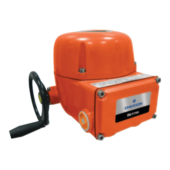
- Page 1 Installation, Operation and Maintenance Manual VCIOM-17109-EN Rev. 0 May 2022 Bettis OM3 - SCE300 Local Interface Module...
- Page 2 Notes Installation, Operation and Maintenance Manual May 2022 VCIOM-17109-EN Rev. 0 This page intentionally left blank...
-
Page 3: Table Of Contents
Installation, Operation and Maintenance Manual Table of Contents VCIOM-17109-EN Rev. 0 May 2022 Table of Contents Section 1: Optional Module 3: Local Interface Module Local Interface Functionality ................. 1 Manufacturer ....................2 Section 2: Assembling Procedure Assembling Procedure .................... 3 Section 3: Description Of OM3 Local Interface Local Operator Interface ................ - Page 4 Notes Installation, Operation and Maintenance Manual May 2022 VCIOM-17109-EN Rev. 0 This page intentionally left blank...
-
Page 5: Section 1: Optional Module 3: Local Interface Module
Installation, Operation and Maintenance Manual Section 1: Optional Module 3: Local Interface Module VCIOM-17109-EN Rev. 0 May 2022 NOTE: The present IOM has to be considered integral part of the IOM for the basic Installation, Operation and Maintenance Manual for Bettis SCE300 electric actuator. Section 1: Optional Module 3: Local Interface Module Local Interface Functionality... -
Page 6: Manufacturer
WARNING Repair work, other than operations outlined in this manual, is strictly reserved to qualified Emerson personnel or to personnel authorized by the company itself. Manufacturer as specified on... -
Page 7: Section 2: Assembling Procedure
Installation, Operation and Maintenance Manual Section 2: Assembling Procedure VCIOM-17109-EN Rev. 0 May 2022 Section 2: Assembling Procedure To assemble the OM3 Local Interface module onto the SCE300 actuator, proceed as follows: • Ensure that all the parts received with the OM3 are available, see Figure 1: Figure 1 OM3 kit for SCE300 actuator Table 1. - Page 8 Section 2: Assembling Procedure Installation, Operation and Maintenance Manual May 2022 VCIOM-17109-EN Rev. 0 • With the Allen key loosen the 4 cover screws and remove the terminal board enclosure cover, see Figures 3. You will see the terminal board inside the actuator. Remove the ground cable from the cover in the enclosure.
- Page 9 Installation, Operation and Maintenance Manual Section 2: Assembling Procedure VCIOM-17109-EN Rev. 0 May 2022 • Connect the Local Interface module to the ground stud by screwing the ‘ground kit’ (screw + toothed washer). Figure 5 Grounding the Local Interface • Take the 4 screws for connecting the Local Interface black connector to the terminal board, in pos.
- Page 10 Section 2: Assembling Procedure Installation, Operation and Maintenance Manual May 2022 VCIOM-17109-EN Rev. 0 • Now the Local Interface is connected to the actuator, see Figure 8. Take the 4 screws removed from terminal board cover and use them to fix the Local •...
-
Page 11: Section 3: Description Of Om3 Local Interface
Installation, Operation and Maintenance Manual Section 3: Description Of OM3 Local Interface VCIOM-17109-EN Rev. 0 May 2022 Section 3: Description of OM3 Local Interface Figure 10 Table 2. Pos. Description 2-position lockable selector switch OPEN push-button CLOSE push-button OPEN position and correct with maneuver indicating LED (default green color) CLOSE position and correct with maneuver indicating LED (default red color) Local Operator Interface The following functions are available through the SCE300 Local Interface module (OM3):... -
Page 12: Description Of The Local Interface
Section 3: Description Of OM3 Local Interface Installation, Operation and Maintenance Manual May 2022 VCIOM-17109-EN Rev. 0 Description of the Local Interface 3.2.1 2-Position Selector • Local: to enable the local control only. • Remote: to enable the remote control and local control via Bluetooth with PC and PDA. 3.2.2 LEDs Indicating the Position of the SCE300 Actuator The two LEDs indicate the actuator status according to the following logic:... -
Page 13: Section 4: To Locally Operate The Actuator
Installation, Operation and Maintenance Manual Section 4: To Locally Operate the Actuator VCIOM-17109-EN Rev. 0 May 2022 Section 4: To Locally Operate the Actuator Once you have made sure that the actuator basic configuration is as requested by your application, bring the 2-position selector to LOCAL and control the actuator by OPEN and CLOSE pushbuttons. -
Page 14: Section 5: Om3 Wiring Diagram
Installation, Operation and Maintenance Manual Section 5: OM3 Wiring Diagram May 2022 VCIOM-17109-EN Rev. 0 Section 5: OM3 Wiring Diagram Figure 11 BLINKER LOCAL SELECTOR MONITOR RELAY RELAY Remote commands Note 6 Output contacts Optional module 3 Note 1 (Note 2, 5) (Note 3) Note 4 NOTES:... -
Page 15: Section 6: Identification
Section 6: Identification Installation, Operation and Maintenance Manual VCIOM-17109-EN Rev. 0 May 2022 Section 6: Identification Water-, Dust-Proof Version SCE300 actuators with OM3 are designed and manufactured according to EN 60529 standards. Specific types of protection are printed on the label, as follows: •... -
Page 16: Explosion-Proof Version
Section 6: Identification Installation, Operation and Maintenance Manual May 2022 VCIOM-17109-EN Rev. 0 Explosion-Proof Version The version of SCE300 with OM3 suitable for installation in hazardous areas is designed and manufactured according to EN 50014, 50018, 50019, EN 50281-1-1 standards. The driven valve or associated gear reducer will form part of a separate risk analysis according to Directive ATEX 94/9/EC and following the EN 13463 norms. -
Page 17: Section 7: Safety Instructions
The Electrical Actuators SCE300 with OM3 are produced by Emerson and identified by Product designation: SCE300-XXX/OM3. For the general Instructions relevant to the Installation, Operation and Configuration, Maintenance and Troubleshooting, the base Instruction and Operating Manual must be used. -
Page 18: Applicable Standards And Regulations
2014/30/EU EMC Directive Terms and Conditions Emerson guarantees each single product to be free from defects and to conform to current goods specifications. Except when differently specified, the warranty period in one year from the date of installation by the first user, or eighteen months from the date of shipment to the first user, whichever occurs first. -
Page 19: Section 8: Installation
Installation, Operation and Maintenance Manual Section 8: Installation VCIOM-17109-EN Rev. 0 May 2022 Section 8: Installation Working Conditions The Electric Actuators SCE300 with OM3 are suitable for the following ambient temperatures from -40 °C to +65 °C (from -40 °F to +149 °F). NOTE: Check the ‘temperature ambient range’... -
Page 20: Section 9: Special Maintenance
Not performing this procedure will invalidate the product safety and contractual guarantee. Original spare parts must be required to Emerson: to ensure that right spare is provided, serial number printed on the Electric Actuator label MUST be specified when spares are ordered. - Page 21 Installation, Operation and Maintenance Manual Notes VCIOM-17109-EN Rev. 0 May 2022 This page intentionally left blank...
- Page 22 Holland Fasor 6 VCIOM-17109-EN ©2022 Emerson. All rights reserved. P. R. China Székesfehérvár 8000 The Emerson logo is a trademark and service mark of Emerson Electric Co. T +86 22 8212 3300 Hungary Bettis is a mark of one of the Emerson family of companies.