
Related Manuals for HP Deskpro EX

Summary of Contents for HP Deskpro EX
- Page 1 Technical Reference Guide For the Compaq Deskpro EX/EXS Series of Personal Computers Covering Models Featuring Intel Celeron and Pentium III Processors And the Intel 815 Chipset...
- Page 3 Provided below is a title block that can be copied and/or cut out and placed into a slip or taped onto the edge of the binder. Deskpro EX Series Personal Computers Featuring Intel Celeron and Pentium III Processors and the Intel 815 Chipset...
- Page 5 Reader Feedback Please feel free to send any questions, suggestions, corrections, or comments regarding this document please to the following email address: [email protected] When responding, please state the title and edition of the referenced document.
- Page 7 For more information regarding specifications and Compaq-specific parts please contact Compaq Computer Corporation. Compaq Deskpro EX Series Personal Computers Document Number 137H-0800A-WWEN First Edition - August 2000 Technical Reference Guide NOTICE Technical Reference Guide First Edition - August 2000 Compaq Deskpro EX Series of Personal Computers...
- Page 8 Technical Reference Guide Compaq Deskpro EX Series of Personal Computers First Edition –- August 2000...
-
Page 9: Table Of Contents
CHAPTER 3 PROCESSOR/MEMORY SUBSYSTEM... INTRODUCTION ...3-1 PROCESSOR...3-2 3.2.1 CELERON PROCESSOR...3-2 3.2.2 PENTIUM III PROCESSOR ...3-3 3.2.3 PROCESSOR UPGRADING ...3-4 MEMORY SUBSYSTEM ...3-5 SUBSYSTEM CONFIGURATION ...3-8 Compaq Deskpro EX Series of Personal Computers First Edition - August 2000 Technical Reference Guide... - Page 10 IDE PROGRAMMING...5-1 5.2.2 IDE CONNECTOR...5-3 DISKETTE DRIVE INTERFACE ...5-4 5.3.1 DISKETTE DRIVE PROGRAMMING ...5-5 5.3.2 DISKETTE DRIVE CONNECTOR ...5-7 SERIAL INTERFACE...5-8 5.4.1 RS-232 INTERFACE...5-8 5.4.2 SERIAL INTERFACE PROGRAMMING...5-9 Compaq Deskpro EX Series of Personal Computers First Edition –- August 2000...
- Page 11 INTRODUCTION ...7-1 POWER SUPPLY ASSEMBLY/CONTROL...7-1 7.1.1 POWER SUPPLY ASSEMBLY...7-2 7.1.2 POWER CONTROL...7-3 POWER DISTRIBUTION...7-5 7.2.1 3.3/5/12 VDC DISTRIBUTION ...7-5 7.2.2 LOW VOLTAGE DISTRIBUTION...7-7 SIGNAL DISTRIBUTION ...7-8 Compaq Deskpro EX Series of Personal Computers First Edition - August 2000 Technical Reference Guide...
- Page 12 A.17 DVD/CD-ROM ERROR MESSAGES (33 A.18 NETWORK INTERFACE ERROR MESSAGES (60 A.19 SCSI INTERFACE ERROR MESSAGES (65 A.20 POINTING DEVICE INTERFACE ERROR MESSAGES (8601- Compaq Deskpro EX Series of Personal Computers )... A-3 )... A-4 )... A-4 ) ... A-5 ) ...
- Page 13 FUNCTIONAL DESCRIPTION ... E-2 DISPLAY MODES... E-3 SOFTWARE SUPPORT INFORMATION... E-4 MONITOR CONTROL ... E-4 CONNECTORS ... E-5 E.6.2 MONITOR CONNECTOR... E-5 E.6.3 VIDEO INTERFACE CONNECTOR ... E-6 Compaq Deskpro EX Series of Personal Computers First Edition - August 2000 Technical Reference Guide...
-
Page 14: List Of Figures
OLTAGE UPPLY AND 7–5. S IGURE IGNAL ISTRIBUTION 7–6. H ... 7-9 IGURE EADER INOUTS viii Compaq Deskpro EX Series of Personal Computers LIST OF FIGURES ERIES ERSONAL OMPUTERS WITH ... 2-5 ERIES RONT IEWS ... 2-6 ERIES IEWS (DT) C... - Page 15 LOCK DIAGRAM , (F DB-15, EMALE AS VIEWED FROM REAR (26-P ) ...E-6 EADER Compaq Deskpro EX Series of Personal Computers First Edition - August 2000 Technical Reference Guide ... C-3 ... C-6 ... C-6 ... D-1 AYOUT ... D-2 ).
-
Page 16: List Of Tables
ABLE ARALLEL NTERFACE 5–11. P ABLE ARALLEL NTERFACE 5–12. DB-25 P ABLE ARALLEL ONNECTOR Compaq Deskpro EX Series of Personal Computers LIST OF TABLES ... 1-3 ... 2-2 ATRIX ... 2-14 UNCTIONS ... 2-16 OMPARISON ... 2-17 ... 2-17 ... 2-18 ... - Page 17 ... A-11 RROR ESSAGES ... C-11 OMMANDS ... C-12 ... D-3 RAPHICS ISPLAY ODES ... D-4 ONDITIONS ... D-5 INOUT Compaq Deskpro EX Series of Personal Computers First Edition - August 2000 Technical Reference Guide ... 5-28 ... 6-5 EGISTERS...
- Page 18 RAPHICS E–2. M ABLE ONITOR OWER ANAGEMENT E–3. DB-15 M ABLE ONITOR ONNECTOR E–4. M ABLE ULTIMEDIA NTERFACE Compaq Deskpro EX Series of Personal Computers ...E-3 ISPLAY ODES ...E-4 ONDITIONS ...E-5 INOUT ...E-6 ONNECTOR INOUT First Edition –- August 2000...
-
Page 19: Chapter 1 Introduction
Chapter 1 INTRODUCTION ABOUT THIS GUIDE This guide provides technical information about the Compaq Deskpro EX Series of Personal Computers. This document includes information regarding system design, function, and features that can be used by programmers, engineers, technicians, and system administrators. -
Page 20: Notational Conventions
(MSb) of a byte. Bytes, words, double words, and quad words are typically shown with most-significant portions on the left or top and the least-significant portions on the right or bottom respectively. Compaq Deskpro EX Series of Personal Computers Index port Data port... -
Page 21: Common Acronyms And Abbreviations
Compaq system management / Compaq server management digital-to-analog converter direct current DOS compatibility hole Display Data Channel direction flag Table 1-1. Acronyms and Abbreviations Compaq Deskpro EX Series of Personal Computers Review Copy - August 2000 Technical Reference Guide Continued... - Page 22 InfraRed Data Association interrupt request industry standard architecture Kb / KB kilobits / kilobytes (x 1024 bits / x 1024 bytes) Kb/s kilobits per second kilogram kilohertz kilovolt Compaq Deskpro EX Series of Personal Computers Review Copy – August 2000 Continued...
- Page 23 (monitor input) Relative humidity RIMM RDRAM inline memory module root mean square read-only memory revolutions per minute real time clock read/write Review Copy - August 2000 Technical Reference Guide Compaq Deskpro EX Series of Personal Computers Continued...
- Page 24 VESA Video Electronic Standards Association video graphics adapter vibrato VLSI very large scale integration VRAM Video RAM watt Wake-On-LAN WRAM Windows RAM zero flag zero insertion force (socket) Compaq Deskpro EX Series of Personal Computers Review Copy – August 2000...
-
Page 25: Chapter 2 System Overview
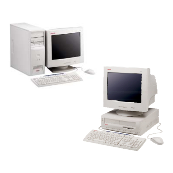
2. Chapter 2 SYSTEM OVERVIEW INTRODUCTION Compaq Deskpro EX Series Personal Computers (Figure 2-1) deliver quality computing and meet essential business needs. Based on the latest Intel Celeron and Pentium III processors with the Intel 815 Chipset, these systems provide high performance for price-conscious businesses. This guide also covers Deskpro EXS models, which are hardware/software packages that provide ready-to-run solutions for small-to-medium businesses. -
Page 26: Features And Options
Power-on password Administrator password Serial/parallel port disable PS/2 Compaq Easy-Access keyboard w/Windows support PS/2 Compaq Scroll Mouse Table 2-1 shows the differences in features between the Deskpro EX series: Table 2-1. Feature Difference Matrix Form factor Chassis type Drive bays... -
Page 27: Options
Compaq P700 17” CRT Compaq P900 19” CRT Compaq P1100 21” CRT Compaq TFT5010 15” Flat Panel Compaq TFT8020 18” Flat Panel PS115 Speakers PS330 Speakers Compaq Deskpro EX Series of Personal Computers First Edition - August 2000 Technical Reference Guide... -
Page 28: Mechanical Design
Minitower (MT) – an ATX-type unit providing the most expandability and being adaptable to desktop or floor-standing placement. The following subsections describe the mechanical (physical) aspects of the Compaq Deskpro EX Series models. CAUTION: Voltages are present within the system unit whenever the unit is plugged into a live AC outlet, regardless of the “Power On”... -
Page 29: Cabinet Layouts
CD-ROM drive activity LED CD-ROM drive door open/close button 1.44-MB diskette drive activity LED 1.44-MB diskette drive eject button Figure 2–2. Compaq Deskpro EX Series, Front Views Minitower (MT) Compaq Deskpro EX Series of Personal Computers First Edition - August 2000... - Page 30 Chapter 2 System Overview 2.3.1.2 Rear Views 11 12 Desktop (DT) Item Figure 2–3. Compaq Deskpro EX Series, Rear Views Compaq Deskpro EX Series of Personal Computers Description AC line In Connector (115V/230V) Line voltage switch PS/2 keyboard I/F connector PS/2 mouse I/F connector USB I/F connectors (top, port B;...
-
Page 31: Chassis Layouts
For detailed information on servicing the chassis refer to the multimedia training CD-ROM and/or the maintenance and service guide for these systems. Figure 2-4 shows the layout for the Deskpro EX desktop (DT). This chassis provides: Easy access to expansion slots and all socketed system board components. - Page 32 Chapter 2 System Overview Figure 2-5 shows the layout for the Deskpro EX minitower (MT). This chassis provides: Four 5 ¼-inch drive bays and one 3 ½-inch drive bay Easy access to expansion slots and all socketed system board components.
-
Page 33: Board Layout
Piezo speaker AGP slot connector Chassis fan header Auxiliary power LED Serial port B connector Audio Mic In, Line In, HP Out connectors Monitor connector Parallel port connector Serial port A connector Top: USB port B; Bottom: USB port A... -
Page 34: System Architecture
Chapter 2 System Overview SYSTEM ARCHITECTURE The Compaq Deskpro EX systems covered in this guide feature an architecture based on an Intel Pentium III or Celeron processor working with the Intel 815 chipset (Figure 2-7). All models use SDRAM for system memory, provide AGP 4X graphics support, and include PCI bus expansion capability. -
Page 35: Figure 2-7. Compaq Deskpro
AGP 4X Optional 4-MB Controller GPA Card Monitor NVIDIA Graphics Cntlr. Card Hard Drive Audio Audio Subsystem Figure 2–7. Compaq Deskpro EX Architecture, Block diagram Pentium III Celeron Processor 66-/100-/133- MHz FSB i740 815 Chipset 82815 GMCH SDRAM Cntlr. Hub Link Pri. -
Page 36: Processors
Chapter 2 System Overview 2.4.1 PROCESSORS The Compaq Deskpro EX series includes models based on Celeron and Pentium III processors. These processors are backward-compatible with software written for the Pentium II, Pentium MMX, Pentium Pro, Pentium, and x86 microprocessors. Both processor architectures include a floating-point unit, first and secondary caches, and enhanced performance for multimedia applications through the use of multimedia extension (MMX) instructions. - Page 37 Streaming SIMD Extension (SSE) support for higher video, audio, and speech processing 32-KB first-level cache On-die (full speed) 256-KB ECC second level cache Improved speculative instruction processing Identification number Compaq Deskpro EX Series of Personal Computers First Edition - August 2000 Technical Reference Guide 2-13...
-
Page 38: Chipset
Table 2-3. Support Component Functions Component Name LPC47B357 I/O Controller AD1885 Audio Codec 2-14 Compaq Deskpro EX Series of Personal Computers Table 2-2. 815 Chipset Functions Table 2-3. Support Component Functions Function... -
Page 39: Processor/Memory Subsystem
All models feature two Universal Serial Bus (USB) ports that provide a 12Mb/s interface for peripherals. The USB provides hot plugging/unplugging (Plug ’n Play) functionality. Compaq Deskpro EX Series of Personal Computers First Edition - August 2000 Technical Reference Guide... -
Page 40: Graphics Subsystem
[1] Dynamic Video Memory Technology (DVMT) allocates portions of system memory, which may supplemented by an optional 4-MB Graphics Performance Accelerator (GPA) card. [2] With 75-Hz vertical refresh. 2-16 Compaq Deskpro EX Series of Personal Computers Table 2-4. Graphics Subsystem Comparison NVIDIA Vanta LT Graphics Card Vanta Cntlr. -
Page 41: Audio Subsystem
SPECIFICATIONS This section includes the environmental, electrical, and physical specifications for the Compaq Deskpro EX Series Personal Computers. Where provided, metric statistics are given in parenthesis. All specifications subject to change without notice. Table 2-5. Environmental Specifications... -
Page 42: Table 2-7. Physical Specifications
Read/Write Heads Average Access Time: Track-to-Track (high/low) Average (high/low) Settling Time Latency Average 2-18 Compaq Deskpro EX Series of Personal Computers Table 2-7. Physical Specifications EX DT 5.10 in (12.95 cm) 14.50 in (36.83 cm) 15.70 in (39.87 cm) 26 lb (11.8 kg) 100 lb (45.5 kg) -
Page 43: Table 2-10. Hard Drives
8.5 ms 9.5 ms 15 ms 21 ms 16383 16383 7200 RPM 7200 RPM SMART III SMART III Compaq Deskpro EX Series of Personal Computers 20.0 GB 5.25” UATA/66 100 MB/s [1] 1.0 ms 9.0 ms 20 ms 16383 7200 RPM... - Page 44 Chapter 2 System Overview This page is intentionally blank. 2-20 Compaq Deskpro EX Series of Personal Computers First Edition – August 2000...
-
Page 45: Chapter 3 Processor/Memory Subsystem
Chapter 3 PROCESSOR/MEMORY SUBSYSTEM INTRODUCTION This chapter describes the processor/cache memory subsystem of Compaq Deskpro EX Personal Computers. These systems feature a Celeron or Pentium III processor and the 815 chipset (Figure 3-1). Each system supports one or two SDRAM DIMMs and implements the 82815 GMCH’s integrated i740 3D graphics controller (covered in Chapter 6). -
Page 46: Celeron Processor
Chapter 3 Processor/Memory Subsystem PROCESSOR The Compaq Deskpro EX is shipped with either a Celeron or Pentium III processor. 3.2.1 CELERON PROCESSOR The Celeron processor (Figure 3-2) uses a dual-ALU CPU with branch prediction and MMX support, floating point unit (FPU) for math coprocessing, a 32-KB primary (L1) cache, and a 128- KB secondary (L2) ECC cache. -
Page 47: Pentium Iii Processor
133 MHz 733 MHz 133 MHz 800 MHz 133 MHz 866 MHz 133 MHz 933 MHz 133 MHz Compaq Deskpro EX Series of Personal Computers First Edition - August 2000 Technical Reference Guide Core Voltage 1.65 1.65 1.65 1.65 1.65 1.65... -
Page 48: Processor Upgrading
“tuned’ to take advantage of the Pentium III processor’s special features (such as SSE instruction execution). This is more of a concern with systems running Windows 98 and NT. Compaq Deskpro EX Series of Personal Computers First Edition - August 2000... -
Page 49: Memory Subsystem
If an incompatible DIMM is detected the NUM LOCK will blink for a short period of time during POST and an error message may or may not be displayed before the system hangs. Compaq Deskpro EX Series of Personal Computers First Edition - August 2000... - Page 50 Can also be used to indicate s/n mismatch and flag system adminstrator of possible system Tampering. [11] Contains the socket # of the module (first module is “1”). Intended as backup identifier (refer to note [10]). Compaq Deskpro EX Series of Personal Computers Table 3-3. SPD Address Map (SDRAM DIMM) Notes...
-
Page 51: Figure 3-4. System Memorym
1 MB System BIOS Area (64 KB) Extended BIOS Area (64 KB) Option ROM (128 KB) Graphics/SMRAM RAM (128 KB) 640 KB Fixed Mem. Area (128 KB) 512 KB Base Memory (512 KB) Compaq Deskpro EX Series of Personal Computers... -
Page 52: Subsystem Configuration
Assume unmarked locations/gaps as reserved. [1] = 0090h for AGP (external graphics) implementation; = 0080h for GFX (internal i740) implementation. [2] = 8 for AGP; = 0 for GFX. Compaq Deskpro EX Series of Personal Computers Table 3-4. Reset Value Config. -
Page 53: Chapter 4 System Support
Register map and miscellaneous functions (4.8) page 4-38 This chapter covers functions provided by off-the-shelf chipsets and therefore describes only basic aspects of these functions as well as information unique to Compaq Deskpro EX Personal Computers. For detailed information on specific components, refer to the applicable manufacturer’s documentation. -
Page 54: Pci Bus Overview
Hub Link I/F Hub Link Bus Hub Link I/F PCI Bridge Function Bus #2 Figure 4-1. PCI Bus Devices and Functions Compaq Deskpro EX Series of Personal Computers PCI Bus #1 (AGP Bus) Bus #0 Bridge Function 82801AA ICH Component... -
Page 55: Pci Bus Transactions
Configuration Cycle Type ID. 00 = Type 0 01 = Type 1 PCI Configuration Data Register I/O Port 0CFCh, R/W, (8-, 16-, 32-bit access) Function 31..0 Configuration Data. Compaq Deskpro EX Series of Personal Computers First Edition - August 2000 Technical Reference Guide... -
Page 56: Figure 4-2. Configurationc
NOTES: [1] Bus number in standard configuration. Can shift up if an AGP device with an additional PCI bridge is installed in the AGP slot. Not used. Compaq Deskpro EX Series of Personal Computers 24 23 16 15 11 10... -
Page 57: Table 4-2. System Board Pci D
8086h 8086h 8086h 8086h 8086h 8086h 8086h 8086h 8086h Compaq Deskpro EX Series of Personal Computers First Edition - August 2000 Technical Reference Guide 24 23 16 15 Device-Specific Area Bridge Control Int. Pin Int. Line Expansion ROM Base Address... -
Page 58: Pci Bus Master Arbitration
Note that most CPU-to-DRAM and AGP-to-DRAM accesses can occur concurrently with PCI traffic, therefore reducing the need for the Host/PCI bridge to compete for PCI bus ownership. Compaq Deskpro EX Series of Personal Computers Table 4-3. Device... -
Page 59: Option Rom Mapping
33-MHz rate. Generally transparent in operation, the LPC bus becomes a factor primarily during the configuration of DMA channel modes (see section 4.4.3 “DMA”). Compaq Deskpro EX Series of Personal Computers First Edition - August 2000... -
Page 60: Pci Configuration
Serial IRQ Control 65-87h Reserved Dev. 31 Error Config. NOTE: [1] Value for each byte. Assume unmarked locations/gaps as reserved. Compaq Deskpro EX Series of Personal Computers Table 4-4. LPC Bridge Configuration Registers (ICH, Function 0, Device 31) Reset Config. Value Addr. -
Page 61: Pci Connector
AD01 AD00 +5 VDC +5 VDC ACK64- REQ64- +5 VDC +5 VDC +5 VDC +5 VDC Compaq Deskpro EX Series of Personal Computers First Edition - August 2000 Technical Reference Guide B Signal A Signal Reserved C/BE7- C/BE6- C/BE5- C/BE4-... -
Page 62: Agp Bus Overview
FRAME- signal. There are two basic types of transactions on the AGP bus: data requests (addressing) and data transfers. These actions are separate from each other. 4-10 Compaq Deskpro EX Series of Personal Computers First Edition - August 2000... - Page 63 “001” indicating high priority. The signal level for AGP 1X transfers may be 3.3 or 1.5 VDC. GNT- TRDY- ST0..2 Figure 4-5. AGP 1X Data Transfer (Peak Transfer Rate: 266 MB/s) Compaq Deskpro EX Series of Personal Computers First Edition - August 2000 Technical Reference Guide 4-11...
- Page 64 AD_STBx-. The signal level for AGP 4X transfers is 1.5 VDC. AD_STBx AD_STBx- ST0..2 Figure 4-7. AGP 4X Data Transfer (Peak Transfer Rate: 1064 MB/s) 4-12 Compaq Deskpro EX Series of Personal Computers D3B D4A D4B D3B D4A D4B First Edition - August 2000...
-
Page 65: Agp Configuration
Memory Limit Address 24, 25h Prefetch Mem. Base Addr. 26, 27h Prefetch Mem. Limit Addr. PCI/PCI Bridge Control 3F-FFh Reserved Compaq Deskpro EX Series of Personal Computers First Edition - August 2000 Technical Reference Guide Reset Value 02A0h FFF0h 0000h... -
Page 66: Agp Connector
VDDQ = 3.3 VDC when TYPE DET- is left open by AGP 1X/2X card. VDDQ = 1.5 VDC when TYPE DET- is grounded by AGP 4X card. 4-14 Compaq Deskpro EX Series of Personal Computers Table 4-7. AGP Bus Connector Pinout... -
Page 67: System Resources
8259 mode APIC mode LPC47B357 I/O Cntlr. Interrupt Serial IRQ Serializer 82801 Interrupt Processing Compaq Deskpro EX Series of Personal Computers First Edition - August 2000 Technical Reference Guide INTR- Microprocessor APIC Bus 4-15... -
Page 68: Table 4-8. Maskable Interrupt
Windows 95 or 98 operating system will need to run in 8259 mode. The mode is selectable through the Setup utility (access with F10 key during boot sequence). 4-16 Compaq Deskpro EX Series of Personal Computers Table 4-8. Source (Typical) -
Page 69: Non-Maskable Interrupts
Microprocessor internal error (activating IERRA or IERRB) The SERR- and PERR- signals are routed through the ICH component, which in turn activates the NMI to the microprocessor. Table 4-9. Compaq Deskpro EX Series of Personal Computers First Edition - August 2000 Technical Reference Guide 4-17... - Page 70 APM BIOS to service the SMI- according to the cause of the timeout. Although the SMI- is primarily used for power managment the interrupt is also employed for the QuickLock/QuickBlank functions as well. 4-18 Compaq Deskpro EX Series of Personal Computers First Edition - August 2000...
-
Page 71: Direct Memory Access
PCI expansion devices. Table 4-10. Device ID Spare Audio subsystem Diskette drive ECP LPT1 Cascade for controller 1 Spare Spare Spare Compaq Deskpro EX Series of Personal Computers First Edition - August 2000 Technical Reference Guide 4-19... - Page 72 The size of the the block of data that can be moved or addressed is measured in 16-bits (words) rather than 8-bits (bytes). The words must always be addressed on an even boundary. 4-20 Compaq Deskpro EX Series of Personal Computers Table 4-11. Page Register I/O Port 087h...
- Page 73 003h 004h 004h 005h 005h 006h 006h 007h 007h 00Dh 00Ch 00Dh 00Eh Compaq Deskpro EX Series of Personal Computers First Edition - August 2000 Technical Reference Guide Controller 2 0D0h 0D0h 0D6h 0D4h 0DEh 0D2h 0C0h 0C0h 0C2h 0C2h...
-
Page 74: System Clock Distribution
Crystal Certain clock outputs are turned off during reduced power modes to conserve energy. Clock output control is handled through the SMBus interface by BIOS. 4-22 Compaq Deskpro EX Series of Personal Computers Table 4-13. Destination Processor, GMCH DIMM sockets ICH, AGP Graphics Cntlr. -
Page 75: Real-Time Clock And Configuration Memory
Extended Config. Register A Memory Area Year (128 bytes) Month Day of Week Standard Config. Memory Area (114 bytes) RTC Area (14 bytes) CMOS Compaq Deskpro EX Series of Personal Computers First Edition - August 2000 Technical Reference Guide 4-23... -
Page 76: Cmos Archive And Restore
Enhanced hard drive support Reserved Power management functions NOTES: Assume unmarked gaps are reserved. RTC Control Register A, Byte 0Ah 4-24 Compaq Deskpro EX Series of Personal Computers Table 4-14. Configuration Memory (CMOS) Map Location Function System board ID System architecture data... - Page 77 Configuration Byte 0Eh, Diagnostic Status Default Value = 00h This byte contains diagnostic status data. First Edition - August 2000 Technical Reference Guide Sunday in April, retreat 1 hour on last Sunday in Compaq Deskpro EX Series of Personal Computers 4-25...
- Page 78 0100 = Type 4 0101 = Type 5 0110 = Type 6 0111 = Type 7 4-26 Compaq Deskpro EX Series of Personal Computers 1000 = Type 8 1001 = Type 9 1010 = Type 10 1011 = Type 11...
- Page 79 Configuration Bytes 17h and 18h, Extended Memory Size Bytes 17h and 18h hold a 16-bit value that specifies the extended memory size in 1-KB increments. Configuration Bytes 19h-1Ch, Hard Drive Types First Edition - August 2000 Technical Reference Guide Compaq Deskpro EX Series of Personal Computers 4-27...
- Page 80 01 = I/O ports 878h-87Ch 11 = neither place Configuration Byte 26h, Auxiliary Peripheral Configuration Default Value = 00h Function I/O Delay Select 00 = 420 ns (default) 4-28 Compaq Deskpro EX Series of Personal Computers First Edition - August 2000...
- Page 81 00010 = 1 MB 00011 = 1.5 MB 11111 = 15.5 MB Configuration Byte 29h, Miscellaneous Configuration Data Default Value = 00h Function 7..5 Reserved First Edition - August 2000 Technical Reference Guide Compaq Deskpro EX Series of Personal Computers 4-29...
- Page 82 1 = Numlock on at power on Screen Blank Control: 0 = No screen blank 1 = Screen blank w/QuickLock 4..0 ScreenSave Timeout. (Index to SIT monitor timeout record) 000000 = Disabled 4-30 Compaq Deskpro EX Series of Personal Computers First Edition - August 2000...
- Page 83 0 = Not installed, 1 = Installed Standard Numeric Coprocessor Present: 0 = Not installed, 1 = Installed 3..0 Reserved Configuration Byte 34h, International Language Support Default Value = 00h First Edition - August 2000 Technical Reference Guide Compaq Deskpro EX Series of Personal Computers 4-31...
- Page 84 Row 0 Error Detect 0 = No single bit error detected. 1 = Single bit error detected. Configuration Byte 37h-3Fh, Power-On Password These eight locations hold the power-on password. 4-32 Compaq Deskpro EX Series of Personal Computers First Edition - August 2000...
-
Page 85: System Management
The Setup utility may be configured to be always changeable or changeable only by entering a password. The password is held on CMOS and, if forgotten, will require that CMOS be cleared (refer to section 4.6). Compaq Deskpro EX Series of Personal Computers First Edition - August 2000 Technical Reference Guide... -
Page 86: Cable Lock Provision
The disabling of the serial, parallel, and diskette interfaces are a function of the LPC47B357 I/O controller. The USB ports are controlled through the 82801 ICH. 4-34 Compaq Deskpro EX Series of Personal Computers First Edition - August 2000... -
Page 87: Power Management
NUM Lock CAPs Lock Blinking Blinking [4] Blinking [4] Blinking [5] Blinking [5] On [6] Compaq Deskpro EX Series of Personal Computers First Edition - August 2000 Technical Reference Guide Scroll Lock Blinking Blinking Blinking [4] Blinking [5] On [6]... -
Page 88: Temperature Sensing
I/O controller is asserted, resulting in the I/O controller’s LED logic to blink the front panel Power-On LED red at approximately four times a second. 4-36 Compaq Deskpro EX Series of Personal Computers Table 4-16. Desktop Minitower... -
Page 89: System Cooling
R77 in place to apply +7 VDC to auxiliary fan for reduced noise level. Figure 4-11. Fan Control Block Diagram Aux. Chassis Fan Header P216 R77 [1] R78 [1] Compaq Deskpro EX Series of Personal Computers First Edition - August 2000 Technical Reference Guide Heat Sink Fan Header 4-37... -
Page 90: Register Map And Miscellaneous Functions
Assume unmarked gaps are unused, reserved, or used by functions that employ variable I/O address mapping. Some ranges may include reserved addresses. 4-38 Compaq Deskpro EX Series of Personal Computers Table 4-17. System I/O Map First Edition - August 2000... -
Page 91: 82801 Ich General Purpose Functions
Password Enable SIO SMI S3 Power Control SIO 32-KHz Clock SMBus Clock SMBus Data NOTE: NC = not connected (not used). Table 4-18. Direction Compaq Deskpro EX Series of Personal Computers First Edition - August 2000 Technical Reference Guide 4-39... -
Page 92: Lpc47B357 I/O Controller Functions
Write 30h to I/O register 2Eh. Write 01h to I/O register 2Fh (this activates the interface). Writing AAh to 2Eh deactivates the configuration phase. 4-40 Compaq Deskpro EX Series of Personal Computers Table 4-19. Reset Value First Edition - August 2000... -
Page 93: Lpc47B357 Gpio R
PWR Button Out PS On Remote Off System ID 0 [1] System ID 1 [1] Chassis Fan Sense Pwr SEL S3 3.3 VDC On Compaq Deskpro EX Series of Personal Computers First Edition - August 2000 Technical Reference Guide Direction 4-41... - Page 94 PS On signal according to the mode (legacy or ACPI) selected. Refer to chapter 7 for more information regarding power management. 4-42 Compaq Deskpro EX Series of Personal Computers Power LED Steady green...
-
Page 95: Chapter 5 Input/Output Interfaces
The IDE interface is configured as a PCI device during POST and controlled through I/O-mapped registers at runtime. page 5-1 page 5-4 page 5-8 page 5-10 page 5-14 page 5-20 page 5-24 page 5-30 Compaq Deskpro EX Series of Personal Computers First Edition - August 2000 Technical Reference Guide... - Page 96 Bus Master IDE Status (Secondary) Bus Master IDE Descriptor Pointer (Sec.) NOTE: Unspecified gaps are reserved, will return indeterminate data, and should not be written to. 5-2 Compaq Deskpro EX Series of Personal Computers Table 5-1. Reset PCI Conf. Value Addr.
-
Page 97: Ide Connector
16-bit I/O Address 1 DSKPDIAG Pass Diagnostics Address 0 Address 2 CS0- Chip Select CS1- Chip Select HDACTIVE- Drive Active (front panel LED) [5] Ground Compaq Deskpro EX Series of Personal Computers First Edition - August 2000 Technical Reference Guide... -
Page 98: Diskette Drive Interface
Result phase, in which case the Execution phase can be followed by a Command phase. During periods of inactivity, the diskette drive controller is in a non-operation mode known as the Idle phase. 5-4 Compaq Deskpro EX Series of Personal Computers First Edition – August 2000... -
Page 99: Diskette Drive Programming
Table 5-5. The diskette drive controller of the LPC47B357 operates in the PC/AT mode in these systems. Table 5–5. Diskette Drive Interface Control Registers Table 5-4. Reset Value 03F0h Compaq Deskpro EX Series of Personal Computers First Edition - August 2000 Technical Reference Guide... - Page 100 <1,0> Data rate select (00 = 500 Kb/s, 01 = 300 Kb/s, 10 = 250 Kb/s, 11 = 2/1 Mb/s) NOTE: The most recently written data rate value to either DRSR or CCR will be in effect. 5-6 Compaq Deskpro EX Series of Personal Computers Table 5-5. First Edition – August 2000...
-
Page 101: Diskette Drive Connector
WR DATA- WR ENABLE- TRK 00- WR PRTK- RD DATA- SIDE SEL- DSK CHG- Compaq Deskpro EX Series of Personal Computers First Edition - August 2000 Technical Reference Guide Description Drive head direction control Ground Drive head track step control... -
Page 102: Serial Interface
The standard RS-232-C limitation of 50 feet (or less) of cable between the DTE (computer) and DCE (modem) should be followed to minimize transmission errors. Higher baud rates may require shorter cables. 5-8 Compaq Deskpro EX Series of Personal Computers Table 5-7. DB-9 Serial Connector Pinout Signal First Edition –... -
Page 103: Serial Interface Programming
Line Control Register 3FCh 2FCh Modem Control Register 3FDh 2FDh Line Status Register 3FEh 2FEh Modem Status Table 5-8. Table 5-9. Serial Interface Control Registers Compaq Deskpro EX Series of Personal Computers First Edition - August 2000 Technical Reference Guide... -
Page 104: Parallel Interface
The SPP mode uses three registers for operation: the Data register (DTR), the Status register (STR) and the Control register (CTR). Address decoding in SPP mode includes address lines A0 and A1. 5-10 Compaq Deskpro EX Series of Personal Computers First Edition – August 2000... -
Page 105: Enhanced Parallel Port Mode
DMA and RLE are inhibited. 5.5.4 PARALLEL INTERFACE PROGRAMMING Programming the parallel interface consists of configuration, which typically occurs during POST, and control, which occurs during runtime. Compaq Deskpro EX Series of Personal Computers First Edition - August 2000 Technical Reference Guide 5-11... -
Page 106: Table 5-10. Parallel Interface
Base + 401h Configuration Register B Base + 402h Extended Control Register Base Address: LPT1 = 378h, LPT2 = 278h, LPT3 = 3BCh 5-12 Compaq Deskpro EX Series of Personal Computers Table 5-10. Table 5-11. Parallel Interface Control Registers Mode Ports... -
Page 107: Parallel Interface Connector
ECP modes: Initialize or Reverse Req. Table 5-12. DB-25 Parallel Connector Pinout Signal ERR- INIT- SLCTIN- Compaq Deskpro EX Series of Personal Computers First Edition - August 2000 Technical Reference Guide Function Line Feed [2] Error [3] Initialize Paper [4] Select In / Address. -
Page 108: Keyboard/Pointing Device Interface
Tcl (Clock Low) Tch (Clock High) Th (Data Hold) Tss (Stop Bit Setup) Tsh (Stop Bit Hold) Figure 5-5. 8042-To-Keyboard Transmission of Code EDh, Timing Diagram 5-14 Compaq Deskpro EX Series of Personal Computers Tcl Tch Minimum Maximum 0 us 80 us... - Page 109 Clears keyboard buffer and prepares to receive key ID. [1] Clears keyboard buffer and prepares to receive key ID. [1] 8042 detected error in keyboard transmission. Resets program, runs keyboard BAT, defaults to Mode 2. Compaq Deskpro EX Series of Personal Computers 5-15...
-
Page 110: Pointing Device Interface Operation
The keyboard interface configuration registers are listed in the following table: Table 5–14. Keyboard Interface Configuration Registers Keyboard Interface Configuration Registers Index Address Function Activate Primary Interrupt Select Secondary Interrupt Select Reset and A20 Select 5-16 Compaq Deskpro EX Series of Personal Computers Table 5-14. First Edition – August 2000... - Page 111 Table 5-15 lists the commands that can be sent to the 8042 by the CPU. The 8042 uses IRQ1 for gaining the attention of the CPU. Table 5–15. CPU Commands To The 8042 Compaq Deskpro EX Series of Personal Computers First Edition - August 2000 Technical Reference Guide...
-
Page 112: Keyboard/Pointing Device Interface Connector
Pulse output port. Controls the pulsing of bits <3..0> of the output port (0 = pulse, 1 = don’t pulse). Note that pulsing bit <0> will reset the system. 5.6.4 KEYBOARD/POINTING DEVICE INTERFACE CONNECTOR 5-18 Compaq Deskpro EX Series of Personal Computers Table 5-15. CPU Commands To The 8042... -
Page 113: Figure 5-6. Keyboard Or Pointing
Table 5–16. Keyboard/Pointing Device Connector Pinout Keyboard/Pointing Device Connector Pinout Signal Description DATA Data Not Connected Ground First Edition - August 2000 Technical Reference Guide Table 5-16. Signal Description + 5 VDC Power Clock Not Connected Compaq Deskpro EX Series of Personal Computers 5-19... -
Page 114: Universal Serial Bus Interface
Bit stuffing is employed prior to NRZ1 encoding so that in the event a string of 1’s is transmitted (normally resulting in a steady signal level) a 0 is inserted after every six consecutive 1’s to ensure adequate signal transitions in the data stream. 5-20 Compaq Deskpro EX Series of Personal Computers http://www.usb.org 82801... - Page 115 PID Field Frame Field (8 bits) (11 bits) PID Field Data Field (8 bits) (0-1023 bytes) PID Field (8 bits) Compaq Deskpro EX Series of Personal Computers CRC Field (5 bits) CRC Field (5 bits) CRC Field (16 bits) 5-21...
-
Page 116: Usb Programming
08, 0B Frame List Base Address Start of Frame Modify 10, 11h Port 1 Status/Control 12, 13h Port 2 Status/Control Test Data 5-22 Compaq Deskpro EX Series of Personal Computers Table 5-17. Reset Config. Value Addr. Register 8086h Header Type... -
Page 117: Usb Connector
9.94 ft (3.03 m) 0.057 6.82 ft (2.08 m) 0.091 4.30 ft (1.31 m) 0.145 2.66 ft (0.81 m) 0.232 Compaq Deskpro EX Series of Personal Computers First Edition - August 2000 Technical Reference Guide Description Data (plus) Ground 5-23... -
Page 118: Audio Subsystem
16-ohm (min.) stereo headphones, a pair of powered speakers, or an amplifier. NOTE: The signal at the Headphone/Line Out jack will not drive external speakers directly. Powered (amplified) speakers must be used. 5-24 Compaq Deskpro EX Series of Personal Computers First Edition – August 2000... -
Page 119: Figure 5-10. Audio Subsystem
Aux Audio (L) Aux Audio (R) Figure 5-10. Audio Subsystem Functional Block Diagram First Edition - August 2000 Technical Reference Guide AC97 Link Bus HP Out Audio (L/R) Compaq Deskpro EX Series of Personal Computers Piezo Speaker Headphones/ Line Out 5-25... -
Page 120: Ac97 Audio Controller
Modem codec data (not used in this system) 6-11 Reserved I/O control Figure 5-11. AC’97 Link Bus Protocol 5-26 Compaq Deskpro EX Series of Personal Computers Bit 0 Bit 19 Bit 18 Bit 0 Bit 19 Bit 18 Slot 0... -
Page 121: Audio Codec
Audio Format Left Audio Gain Right Audio Gain /Mixer Gain Gain Compaq Deskpro EX Series of Personal Computers First Edition - August 2000 Technical Reference Guide Data (L) SD IN Data (R) AC97 Sample Audio Link Rate Controller Gen. -
Page 122: Audio Programming
0Ah PC Beep Vol. 8000h 0Ch Phone In Vol. 8008h 0Eh Mic Vol. 8008h 10h Line In Vol. 8808h 12h CD Vol. 8808h 5-28 Compaq Deskpro EX Series of Personal Computers Table 5-21. AC’97 Audio Controller Value Conf. Reset Addr. Register 8086h 14-17h Native Audio Bus Mstr. -
Page 123: Audio Specifications
2.83 Vp-p 1 K ohms (nom) 10 K ohms (min) 16/800 ohms (min/max) 90 db (nom) (into 16 ohms) 46.5 db -94.5 db 20-20 KHz Compaq Deskpro EX Series of Personal Computers First Edition - August 2000 Technical Reference Guide 5-29... -
Page 124: Network Support
Table 5–24. AOL Events Event BIOS Failure OS Problem Missing/Faulty Processor Heartbeat 5-30 Compaq Deskpro EX Series of Personal Computers Table 5-24. AOL Events Description System fails to boot successfully. System fails to load operating system after POST. Processor fails to fetch first instruction. - Page 125 Sample Application Console from the Intel AOL Utilities (item #2 above) First Edition - August 2000 Technical Reference Guide NIC Card in PCI Slot Alert Clock Trace Alert Data Trace Compaq Deskpro EX Series of Personal Computers 82801 ICH 5-31...
-
Page 126: Remote System Alert Support
(Figure 5-15). During system-off conditions the NIC card receives auxiliary power from the 3.3 VDC auxiliary power rail on the PCI bus. 47B357 I/O Cntlr. Processor Figure 5-15. RSA Logic, Block Diagram 5-32 Compaq Deskpro EX Series of Personal Computers System Board Optional NIC Card AOL/SOS Header BIOS Fail... -
Page 127: Table 5-25. Remote Systema
Server-side utility software (available from Compaq). Management console running one of the following: HP OpenView Network Node Manager 6.x Intel LANDesk Client Manager First Edition - August 2000 Technical Reference Guide Table 5-25. Compaq Deskpro EX Series of Personal Computers 5-33... - Page 128 Chapter 5 Input/Output Interfaces This page is intentionally blank. 5-34 Compaq Deskpro EX Series of Personal Computers First Edition – August 2000...
-
Page 129: Chapter 6 Embedded Graphics Subsystem
Upgradeable with either the addition of a 4-MB GPA card or an AGP graphics card page 6-2 page 6-5 page 6-5 page 6-6 page 6-6 Compaq Deskpro EX Series of Personal Computers First Edition - August 2000 Technical Reference Guide... -
Page 130: 815-Based Graphics Functional Description
(display) buffering. Using a process called Dynamic Video Memory Technology (DVMT), the controller dynamically allocates display and texture memory amounts according to the needs of the application. Compaq Deskpro EX Series of Personal Computers 82815 GMCH i740 SDRAM... - Page 131 6 MB 10 MB 10 MB 9 MB 9 MB 9 MB 10 MB Compaq Deskpro EX Series of Personal Computers First Edition - August 2000 Technical Reference Guide FSB I/F & SDRAM Cntlr. Total Graphics Memory w/4 MB GPA Card...
-
Page 132: Display Modes
1600 x 900 1600 x 900 1600 x 1200 NOTE: [1] True color (24-bpp) mode support at these resolutions require the 4-MB GPA card. Compaq Deskpro EX Series of Personal Computers Table 6-1. 815E-Based Graphics Display Modes Bits per pixel Color Depth 16.7M... -
Page 133: 815-Based Graphics Programming
Suspend mode is typically a few seconds. Monitor’s high voltage section and heater circuitry is turned off. Wake up from Off mode is a little longer than from Suspend. Compaq Deskpro EX Series of Personal Computers First Edition - August 2000 Technical Reference Guide... -
Page 134: Monitor Connector
AGP bus and disable the 815-based graphics controller. Dual monitor support is possible by supplementing the 815-based graphics controller with a PCI graphics card. Compaq Deskpro EX Series of Personal Computers Table 6-5. DB-15 Monitor Connector Pinout... -
Page 135: Chapter 7 Power Supply And Distribution
System Board Slots, Chipsets, Logic & Voltage Regulators +3.3 VDC +5 VDC -5 VDC Power Supply +12 VDC Assembly -12 VDC Compaq Deskpro EX Series of Personal Computers First Edition - August 2000 Technical Reference Guide +5 VDC Drives +12 VDC... -
Page 136: Power Supply Assembly
The power supply assembly is contained in a single unit that features a selectable input voltage: 90-132 VAC and 180-264 VAC. Deskpro EX DT systems use a 145-watt supply while Deskpro EX MT systems employ a 200-watt supply. Tables 7-1 and 7-2 list the specifications of the power supplies. -
Page 137: Power Control
Sleep (suspend to RAM) state (S3) Sleep (suspend to Disk) state (S4) Processor not seated Power supply crowbar activated BIOS ROM error Thermal condition: processor has overheated and shut down Compaq Deskpro EX Series of Personal Computers First Edition - August 2000 Technical Reference Guide... -
Page 138: Wake Up Events
A power management event that asserts the PME- signal on the PCI bus can be enabled to cause the power control logic to generate the PS On. Note that the PCI card must be PCI ver. 2.2 compliant to support this function. Compaq Deskpro EX Series of Personal Computers First Edition - August 2000... -
Page 139: Power Distribution
The power supply assembly includes a multi-connector cable assembly that routes +3.3 VDC, +5 VDC, -5 VDC, +12 VC, and -12 VDC to the system board as well as to the individual drive assemblies. Figure 7-2 shows the power supply cabling for the Deskpro EX desktop (DT) models. Power Supply... -
Page 140: Figure 7-3. Deskpro Ex Mt P
Chapter 7 Power and Signal Distribution Figure 7-3 shows the power supply cabling for Deskpro EX minitower (MT) series units. Power Supply Assembly (P/N 190769) Conn. # Pin 1 Pin 2 Pin 3 +3.3 +3.3 P1 [1] +3.3 P2-6 NOTES: [1] This row represents pins 11-20 of connector P1. -
Page 141: Low Voltage Distribution
1.80 VDC 1101 1.40 VDC 1.75 VDC 1110 1.35 VDC 1.70 VDC 1111 1.30 VDC Compaq Deskpro EX Series of Personal Computers First Edition - August 2000 Technical Reference Guide DIMMs VDDQ [1] AGP Bus 2.5 VDC Pull-Up Logic +3.3 VDC... -
Page 142: Signal Distribution
Models with 933 MHz or faster processor. Models with NVIDIA graphcis controller [1] See Figure 7-8 for header pinout. Figure 7–5. Signal Distribution Diagram (Typical Configuration) Compaq Deskpro EX Series of Personal Computers Power On Conn. Pwr Btn, Pwr/HD LED... -
Page 143: Figure 7-6. Header Pinouts
2 PS LED Anode 4 PS LED Cathode 6 PWR BTN 8 PWR BTN GND 10 System ID 12 GND 16 +5 VDC 18 Not connected 2 OS Fail 4 Fan Alert 6 Thermal Alert Compaq Deskpro EX Series of Personal Computers... - Page 144 Chapter 7 Power and Signal Distribution This page is intentionally blank. 7-10 Compaq Deskpro EX Series of Personal Computers First Edition - August 2000...
- Page 145 PnP support (8.6) Power management functions (8.7) USB legacy support (8.8) page 8-2 page 8-4 page 8-6 page 8-13 page 8-15 page 8-17 page 8-24 Compaq Deskpro EX Series of Personal Computers First Edition - August 2000 Technical Reference Guide...
-
Page 146: Chapter 8 Bios Rom
Num Lock, Caps Lock, and Scroll Lock LEDs of the PS/2 keyboard to communicate the status of the ROM flash as follows: Table 8-1. Boot Block Codes Num Lock Cap Lock Compaq Deskpro EX Series of Personal Computers Table 8-1. Boot Block Codes Scroll Lock Meaning Administrator password required. -
Page 147: Changeable Splash Screen
The utility checks to insure that the specified image meets the splash screen requirements listed above or it will not be loaded into the ROM. Compaq Deskpro EX Series of Personal Computers First Edition - August 2000 Technical Reference Guide... -
Page 148: Boot Functions
Flashing a ROM on a system without a functional operating system (OS). Installing an OS. Installing an application. NOTE: The network boot function requires the installation of a compatible network interface controller card. Compaq Deskpro EX Series of Personal Computers First Edition - August 2000... -
Page 149: Memory Detection And Configuration
Hardware failure before graphics initialization. 1 long, 2 short beeps Graphics controller not present or failed to initialize. 1 long, 3 short beeps ROM failure. none Network service mode Compaq Deskpro EX Series of Personal Computers First Edition - August 2000 Technical Reference Guide... -
Page 150: Setup Utility
Save to Diskette Restore from Diskette Set Defaults and Exit Ignore Changes and Exit Save Changes and Exit Storage Device Configuration Compaq Deskpro EX Series of Personal Computers Table 8-3. Setup Utility Functions Description Lists: Product name Processor type/speed/stepping Cache size (L1/L2) - Page 151 Note: If you use a bootable diskette image that you know to be valid, and it does not boot with Diskette MBR Validation enabled, you may need to disable this option in order to use the diskette. Compaq Deskpro EX Series of Personal Computers Continued...
- Page 152 Boot Order Security Setup Password Power-On Password Password Options Smart Cover Compaq Deskpro EX Series of Personal Computers Continued Description Allows user to execute self-tests on IDE hard drives capable of performing the Drive Protection System (DPS) self-tests. Note: This selection will only appear when at least one...
- Page 153 Identifier (UUID) number - If current number is invalid (these ID numbers are normally set in the factory and are used to uniquely identify the system) Keyboard locale setting (e.g., English or German) for System ID entry. Compaq Deskpro EX Series of Personal Computers Continued...
- Page 154 Power-On Options (Advanced users only) Onboard Devices PCI Devices 8-10 Compaq Deskpro EX Series of Personal Computers Continued Description Allows user to set the energy saver mode (advanced, disable, or minimal). Note: In the minimal energy saver mode setting, the...
- Page 155 AGP aperture size window. Appears only if there are multiple PCI video adapters in the system. Allows users to specify which VGA controller will be the “boot” or primary VGA controller. Compaq Deskpro EX Series of Personal Computers 8-11...
-
Page 156: Client Management Functions
The BIOS32 Service Directory is a 16-byte block that begins on a 16-byte boundary between the physical address range of 0E0000h-0FFFFFh. The format is as follows: Offset No. Bytes 8-12 Compaq Deskpro EX Series of Personal Computers Table 8-4. Mode Real, 16-, & 32-bit Prot. Real, 16-, & 32-bit Prot. - Page 157 = Entry point for the service relative to the BASE returned in EBX The following subsections provide a brief description of key Client Management functions. First Edition - August 2000 Technical Reference Guide Compaq Deskpro EX Series of Personal Computers 8-13...
-
Page 158: System Id And Rom Type
<1>=1 DDC2 support = Monitor DDC support <0>=1 DDC1 support <1>=1 DDC2 support <2>=1 Screen blanked during transfer (Failure) = 86h or 87h 8-14 Compaq Deskpro EX Series of Personal Computers System ID ROM Family 06C4h 686P0 First Edition - August 2000... -
Page 159: Temperature Status
PnP function 02 (Set System Device Node) for each devnode (with bit 1 of the control flag set for static configuration) with the results from the calls made prior to invoking this function. Table 8-5. Compaq Deskpro EX Series of Personal Computers First Edition - August 2000 Technical Reference Guide 8-15... -
Page 160: Smbios
NOTE: System information on these systems is handled exclusively through the SMBIOS. The System Information Table (SIT) method (and it’s associated BIOS functions) used on previous systems is no longer supported. 8-16 Compaq Deskpro EX Series of Personal Computers First Edition - August 2000... -
Page 161: Power Management Functions
Setup utility for being disabled or counting down 10, 15, 20, 30, 60, 120, 180, or 240 minutes, after which time the hard drive will spin down. Compaq Deskpro EX Series of Personal Computers First Edition - August 2000... -
Page 162: System Standby
Since the BIOS returns to the currently running software, it is possible for the drive to spin up while the system is in Standby with the screen blanked. 8-18 Compaq Deskpro EX Series of Personal Computers First Edition - August 2000... -
Page 163: Acpi Support
Table 8-6 lists all the APM calls that the O/S can make to the BIOS. These functions are the major difference between PM and APM. Compaq Deskpro EX Series of Personal Computers First Edition - August 2000 Technical Reference Guide... -
Page 164: Apm Bios Functions
Enable/Disable Resume on Ring Enable/Disable Timer Based Request 8-20 Compaq Deskpro EX Series of Personal Computers Table 8-6. APM BIOS Functions Description Allows the O/S to determine if the system's BIOS supports the APM functionality and if so, which version of the specification it supports. -
Page 165: System Timer
NOTE: The O/S (Win98 and later) can use the "Enable/Disable Timer Based Request" APM BIOS call to disable the system timer the BIOS uses so that the O/S can have direct control of the timing. Compaq Deskpro EX Series of Personal Computers First Edition - August 2000 Technical Reference Guide... - Page 166 If not, the processor is halted again. Steps B and C are repeated until a wake-up event occurs. NOTE: These systems will not turn the fan(s) off as in previous systems. 8-22 Compaq Deskpro EX Series of Personal Computers First Edition - August 2000...
-
Page 167: Usb Legacy Support
PS/2 data. The data will be passed to the keyboard controller and processed as in the PS/2 interface. Changing the delay and/or typematic rate of a USB keyboard though BIOS function INT 16 is not supported. Compaq Deskpro EX Series of Personal Computers First Edition - August 2000 Technical Reference Guide... - Page 168 Chapter 8 BIOS ROM This page is intentionally blank. 8-24 Compaq Deskpro EX Series of Personal Computers First Edition - August 2000...
-
Page 169: Appendix A Error Messages And Codes
Appendix A ERROR MESSAGES AND CODES A. Appendix A ERROR MESSAGES AND CODES INTRODUCTION This appendix lists the error codes and a brief description of the probable cause of the error. Note that not all errors listed in this appendix may be applicable to a particular system model and/or configuration. -
Page 170: Power-On Self Test (Post) Messages
Appendix A Error Messages and Codes POWER-ON SELF TEST (POST) MESSAGES Table A–2. Power-On Self Test (POST) Messages Error Message Invalid Electronic Serial Number Network Server Mode Active (w/o kybd) 101-Option ROM Checksum Error 102-system Board Failure 150-Safe POST Active 162-System Options Not Set 163-Time &... -
Page 171: System Error Messages
SYSTEM ERROR MESSAGES (1xx-xx) Table A–3. System Error Messages Message Probable Cause Option ROM error System board failure System board failure 104-01 Master int. cntlr. test fialed 104-02 Slave int. cntlr. test failed 104-03 Int. cntlr. SW RTC inoperative 105-01 Port 61 bit <6>... -
Page 172: Memory Error Messages
Appendix A Error Messages and Codes MEMORY ERROR MESSAGES (2xx-xx) Table A–4. Memory Error Messages Memory Error Messages Message Probable Cause 200-04 Real memory size changed 200-05 Extended memory size changed 200-06 Invalid memory configuration 200-07 Extended memory size changed 200-08 CLIM memory size changed 201-01... -
Page 173: Printer Error Messages
PRINTER ERROR MESSAGES (4xx-xx) Table A–6. Printer Error Messages Message Probable Cause 401-01 Printer failed or not connected 402-01 Printer data register failed 402-02 Printer control register failed 402-03 Data and control registers failed 402-04 Loopback test failed 402-05 Loopback test and data reg. failed 402-06 Loopback test and cntrl. -
Page 174: Diskette Drive Error Messages
Appendix A Error Messages and Codes DISKETTE DRIVE ERROR MESSAGES (6xx-xx) Table A–8. Diskette Drive Error Messages Message Probable Cause 6xx-01 Exceeded maximum soft error limit 6xx-02 Exceeded maximum hard error limit 6xx-03 Previously exceeded max soft limit 6xx-04 Previously exceeded max hard limit 6xx-05 Failed to reset controller... -
Page 175: Modem Communications Error Messages
A.11 MODEM COMMUNICATIONS ERROR MESSAGES (12xx-xx) Table A–10. Serial Interface Error Messages Message Probable Cause 1201-XX Modem internal loopback test 1201-01 UART DLAB bit failure 1201-02 Line input or UART failure 1201-03 Address line failure 1201-04 Data line fault 1201-05 UART control signal failure 1201-06 UART THRE bit failure... -
Page 176: System Status Error Messages
Appendix A Error Messages and Codes A.12 SYSTEM STATUS ERROR MESSAGES (16xx-xx) Table A–11. System Status Error Messages System Status Error Messages Message Probable Cause 1601-xx Temperature violation 1611-xx Fan failure See Table A-18 for additional messages. A.13 HARD DRIVE ERROR MESSAGES (17xx-xx) Table A–12. -
Page 177: Hard Drive Error Messages
A.14 HARD DRIVE ERROR MESSAGES (19xx-xx) Table A–13. Hard Drive Error Messages Message Probable Cause 19xx-01 Drive not installed 19xx-02 Cartridge not installed 19xx-03 Tape motion error 19xx-04 Drive busy erro 19xx-05 Track seek error 19xx-06 Tape write-protect error 19xx-07 Tape already Servo Written 19xx-08 Unable to Servo Write... -
Page 178: Audio Error Messages (3206- Xx
Appendix A Error Messages and Codes A.16 AUDIO ERROR MESSAGES (3206-xx) Table A–15. Audio Error Messages Audio Error Message Message Probable Cause 3206-xx Audio subsystem internal error A.17 DVD/CD-ROM ERROR MESSAGES (33xx-xx) Table A–16. DVD/CD-ROM Drive Error Messages DVD/CD-ROM Drive Error Messages Message Probable Cause 3301-xx... -
Page 179: Scsi Interface Error Messages
A.19 SCSI INTERFACE ERROR MESSAGES (65xx-xx, 66xx-xx, 67xx-xx) Table A–18. SCSI Interface Error Messages Message Probable Cause 6nyy-02 Drive not installed 6nyy-03 Media not installed 6nyy-05 Seek failure 6nyy-06 Drive timed out 6nyy-07 Drive busy 6nyy-08 Drive already reserved 6nyy-09 Reserved 6nyy-10 Reserved... - Page 180 Appendix A Error Messages and Codes This page is intentionally blank. A-12 Compaq Personal Computers Changed - June 2000...
-
Page 181: Introduction
Appendix B ASCII CHARACTER SET Appendix B ASCII CHARACTER SET INTRODUCTION This appendix lists, in Table B-1, the 256-character ASCII code set including the decimal and hexadecimal values. All ASCII symbols may be called while in DOS or using standard text-mode editors by using the combination keystroke of holding the Alt key and using the Numeric Keypad to enter the decimal value of the symbol. - Page 182 Appendix B ASCII Character Set Symbol Ç ü é â ä à å ç ê ë è ï î ì Ä Å É æ Æ ô ö ò û ù ÿ Ö Ü ¢ £ ¥ ₧ ƒ NOTES: [1] Symbol not displayed. Keystroke Guide: Dec # Keystroke(s)
-
Page 183: Appendix C Keyboard
Appendix C KEYBOARD Appendix C KEYBOARD INTRODUCTION This appendix describes the Compaq keyboard that is included as standard with the system unit. The keyboard complies with the industry-standard classification of an “enhanced keyboard” and includes a separate cursor control key cluster, twelve “function” keys, and enhanced programmability for additional functions. -
Page 184: Keystroke Processing
Appendix C Keyboard KEYSTROKE PROCESSING A functional block diagram of the keystroke processing elements is shown in Figure C-1. Power (+5 VDC) is obtained from the system through the PS/2-type interface. The keyboard uses a Z86C14 (or equivalent) microprocessor. The Z86C14 scans the key matrix drivers every 10 ms for pressed keys while at the same time monitoring communications with the keyboard interface of the system unit. -
Page 185: Ps/2-Type Keyboard Transmissions
C.2.1 PS/2-TYPE KEYBOARD TRANSMISSIONS The PS/2-type keyboard sends two main types of data to the system; commands (or responses to system commands) and keystroke scan codes. Before the keyboard sends data to the system (specifically, to the 8042-type logic within the system), the keyboard verifies the clock and data lines to the system. -
Page 186: Usb-Type Keyboard Transmissions
Appendix C Keyboard C.2.2 USB-TYPE KEYBOARD TRANSMISSIONS The USB-type keyboard sends essentially the same information to the system that the PS/2 keyboard does except that the data receives additional NRZI encoding and formatting (prior to leaving the keyboard) to comply with the USB I/F specification (discussed in chapter 5 of this guide). -
Page 187: Keyboard Layouts
C.2.3 KEYBOARD LAYOUTS Figures C-3 through C-8 show the key layouts for keyboards shipped with Compaq systems. Actual styling details including location of the Compaq logo as well as the numbers lock, caps lock, and scroll lock LEDs may vary. C.2.3.1 Standard Enhanced Keyboards 17 18 19 20 21 22 23 24 25 26 27 28 29... -
Page 188: Figure C-5. U.s. Englishw
Appendix C Keyboard C.2.3.2 Windows Enhanced Keyboards 17 18 19 20 21 22 23 24 25 26 27 28 29 40 41 42 43 44 45 46 47 60 61 62 63 64 65 66 67 68 69 70 76 77 78 79 80 81 82 83 84 85 Figure C–5. -
Page 189: Figure C-7. 7-Button Easya
C.2.3.3 Easy Access Keyboards The Easy Access keyboard is a Windows Enhanced-type keyboard that includes special buttons allowing quick internet navigation. Depending on system, either a 7-button or an 8-button layout may be supplied. The 7-button Easy Access Keyboard uses the layout shown in Figure C-7 and is available with either a legacy PS/2-type connection or a Universal Serial Bus (USB) type connection. -
Page 190: Keys
Appendix C Keyboard C.2.4 KEYS All keys generate a make code (when pressed) and a break code (when released) with the exception of the Pause key (pos. 16), which produces a make code only. All keys with the exception of the Pause and Easy Access keys are also typematic, although the typematic action of the Shift, Ctrl, Alt, Num Lock, Scroll Lock, Caps Lock, and Ins keys is suppressed by the BIOS. - Page 191 C.2.4.2 Multi-Keystroke Functions Shift - The Shift key (pos. 75/86), when held down, produces a shift state (upper case) for keys in positions 17-29, 30, 39-51, 60-70, and 76-85 as long as the Caps Lock key (pos. 59) is toggled off.
- Page 192 Appendix C Keyboard C.2.4.4 Easy Access Keystrokes The Easy Access keyboards (Figures C-7 and C-8) include additional keys (also referred to as buttons) used to streamline internet access and navigation. These buttons, which can be re-programmed to provide other functions, have the default functionality described below: 7-Button Easy Access Keyboard: Button #...
-
Page 193: Keyboard Commands
C.2.5 KEYBOARD COMMANDS Table C-1 lists the commands that the keyboard can send to the system (specifically, to the 8042- type logic). Table C–1. Keyboard-to-System Commands Command Key Detection Error/Over/run BAT Completion BAT Failure Echo Acknowledge (ACK) Resend Keyboard ID Note: [1] Modes 2 and 3. - Page 194 Appendix C Keyboard Table C–2. Keyboard Scan Codes Pos. Legend Print Scrn E0 2A E0 37/E0 B7 E0 AA Scroll Lock Pause E1 1D 45 E1 9D C5/na Backspace Insert E0 AA E0 52/E0 D2 E0 2A [4] E0 2A E0 52/E0 D2 E0 AA [6] Home E0 AA E0 52/E0 D2 E0 2A [4] E0 2A E0 47/E0 C7 E0 AA [6]...
- Page 195 Table C-2. Keyboard Scan Codes (Continued) Legend Mode 1 11/91 12/92 13/93 14/94 15/95 16/96 17/97 18/98 19/99 1A/9A 1B/9B Delete E0 53/E0 D3 E0 AA E0 53/E0 D3 E0 2A [4] E0 2A E0 53/E0 D3 E0 AA [6] E0 4F/E0 CF E0 AA E0 4F/E0 CF E0 2A [4] E0 2A E0 4F/E0 CF E0 AA [6]...
- Page 196 Appendix C Keyboard Table C-2. Keyboard Scan Codes (Continued) Pos. Legend Shift (right) E0 AA E0 48/E0 C8 E0 2A [4] E0 2A E0 48/E0 C8 E0 AA [6] Enter Ctrl (left) Alt (left) (Space) Alt (right) Ctrl (right) E0 AA E0 4B/E0 CB E0 2A [4] E0 2A E0 4B/E0 CB E0 AA [6] E0 AA E0 50/E0 D0 E0 2A [4] E0 2A E0 50/E0 D0 E0 AA [6]...
- Page 197 Table C-2. Keyboard Scan Codes (Continued) Pos. Legend Mode 1 Btn 1 E0 1E/E0 9E Btn 2 E0 26/E0 A6 Btn 3 E0 25/E0 A5 Btn 4 E0 23/E0 A3 Btn 5 E0 21/E0 A1 Btn 6 E0 12/E0 92 Btn 7 E0 32/E0 B2 Btn 1...
-
Page 198: Connectors
Appendix C Keyboard CONNECTORS Two types of keyboard interfaces are used in Compaq systems: PS/2-type and USB-type. System units that provide a PS/2 connector will ship with a PS/2-type keyboard but may also support simultaneous connection of a USB keyboard. Systems that do not provide a PS/2 interface will ship with a USB keyboard. -
Page 199: Figure D-1. Compaq /Nvidia
Appendix D COMPAQ/NVIDIA VANTA LT AGP GRAPHICS CARD D. Appendix D Compaq/NVIDIA Vanta LT AGP Graphics Card INTRODUCTION This appendix describes the Compaq/NVIDIA Vanta LT AGP Graphics Card used in the standard configuration on some models and also available as an option. This card (layout shown in the following figure) installs in a system’s AGP slot. -
Page 200: Appendix D Compaq/Nvidia Vanta Lt Agp Graphics Card
Appendix D Compaq/NVIDIA Vanta LT AGP Graphics Card FUNCTIONAL DESCRIPTION The Compaq/NVIDIA Vanta LT Graphics Card provides high performance 2D and 3D display imaging. The card’s AGP design provides an economical approach to 3D processing by off- loading 3D effects such as texturing, z-buffering and alpha blending to the system memory while 8 megabytes of on-board SDRAM stores the main display image. -
Page 201: Display Modes
DISPLAY MODES The 2D graphics display modes supported by the Compaq/NVIDIA Vanta LT Graphics Card are listed in Table D-1. Table D-1. NVIDIA Vanta LT 2D Graphics Display Modes Resolution Bits per pixel 640 x 480 640 x 480 640 x 480 800 x 600 800 x 600 800 x 600... -
Page 202: Software Support Information
Appendix D Compaq/NVIDIA Vanta LT AGP Graphics Card SOFTWARE SUPPORT INFORMATION The Compaq/NVIDIA Vanta LT Pro graphics card is fully compatible with software written for legacy video modes (VGA, EGA, CGA) and needs no driver support for those modes. Drivers are provided with or available for the card to provide extended mode support for the current operating systems and programming environments such as: Windows 98, 95 Windows NT 4.0, 3.51... -
Page 203: Connectors
CONNECTORS There is one connector associated with this graphics card; the monitor connector. NOTE: The graphic card’s edge connector mates with the AGP slot connector on the system board. This interface is described in chapter 4 of this guide. The DB-15 disply/monitor connector is provided for connection of a compatible RGB/analog monitor. - Page 204 Appendix D Compaq/NVIDIA Vanta LT AGP Graphics Card This page is intentionally blank. Compaq Personal Computers Original - August 2000...
-
Page 205: Appendix E Compaq/Nvidia M64 Graphics Card
Appendix E COMPAQ/NVIDIA M64 GRAPHICS CARD Appendix E Compaq/NVIDIA M64 Graphics Card INTRODUCTION This appendix describes the Compaq/NVIDIA M64 Graphics Card, which installs in an AGP slot and is provided standard in some model configurations and optional for other models. This card is available in 16- and 32-MB versions. -
Page 206: Functional Description
Appendix E Compaq/NVIDIA M64 AGP Graphics Card FUNCTIONAL DESCRIPTION The Compaq/NVIDIA M64 AGP Graphics Card is based on the NVIDIA M64 PRO controller. This card supports 3D effects such as texturing, z-buffering and alpha blending. The graphics BIOS code is contained on-board in BIOS ROM. Card AGP 4X Edge... -
Page 207: Display Modes
DISPLAY MODES The 2D graphics modes supported by the Compaq/NVIDIA M64 AGP Graphics Card and its video BIOS are listed in Table E-1. Table E–1. NVIDIA M64 2D Graphics Display Modes Resolution Bits per pixel 640 x 480 640 x 480 640 x 480 800 x 600 800 x 600... -
Page 208: Software Support Information
Appendix E Compaq/NVIDIA M64 AGP Graphics Card SOFTWARE SUPPORT INFORMATION The Compaq/NVIDIA M64 graphics card is fully compatible with software written for legacy video modes (VGA, EGA, CGA) and needs no driver support for those modes. Drivers are provided with or available for the card to provide extended mode support for the current operating systems and programming environments such as: Accelerated drive support for Windows 3.x, Win95, and WinNT MS DirectDraw support for Win95, Win98, WinNT4.0/5.0 (DirectX 5/6/7) -
Page 209: Connectors
CONNECTORS The ATI RAGE IIC graphics card contains two connectors: the monitor (display) connector for attaching a CRT display and a multimedia connector for attaching multimedia peripherals such a TV or other video cards. E.6.2 MONITOR CONNECTOR There are two connector types associated with the graphics subsystem; the display monitor connector and the graphics memory expansion connectors. -
Page 210: Video Interface Connector
Appendix E Compaq/NVIDIA M64 AGP Graphics Card E.6.3 VIDEO INTERFACE CONNECTOR A video interface is provided through a 26-pin header that complies with the VESA standard feature (VSFC) connector VIP specification 1.1. This interface supports streaming of ITU-R Bt656 data (YCrCb 4:2:2 data) at up to 60 MB/s (i.e., using a 60 MHz clock). Figure E-4 shows the video interface connector. - Page 211 INDEX 3D effects ... D-2 abbreviations ... 1-3 AC97 link bus... 5-26 Accelerated Graphics Port (AGP) ... 4-10 acronyms... 1-3 AGP ... 4-10 Alert-On-LAN ... 5-30 AOL... 5-30 AOL requirements ... 5-31, 5-33 APIC... 4-16 APM BIOS support ... 8-19 arbitration, PCI bus master ...
- Page 212 index addressing ... 1-2 interface audio ... 2-17, 5-24 diskette drive ... 5-4 IDE ... 5-1 keyboard/pointing device... 5-14 parallel ... 2-15, 5-10 serial ... 2-15, 5-8 USB ... 2-15, 5-20 interrupts maskable (IRQn)... 4-15 nonmaskable (NMI, SMI)... 4-17 interrupts, PCI ... 4-7 key (keyboard) functions ...C-8 keyboard ...C-1 keyboard (micro)processor ...C-2...
- Page 213 status, LED ... 4-35 system board ... 2-9 system ID... 8-6, 8-14 system memory ... 2-15, 3-5 system resources ... 4-15 system ROM ... 8-1 system status indications... 4-35 TAFI ... 4-37 temperature status ... 8-15 thermal sensing ... 4-36, 4-37 typematic ...C-8 UART ...
- Page 214 This page is intentionally blank.