
Related Manuals for Bosch ACC MT


Summary of Contents for Bosch ACC MT
- Page 1 Installation instructions/Quick-Start-Guide Central controller with touch display Air Center Control ACC MT...
-
Page 2: Table Of Contents
Table of contents Table of contents 6 System handover ......21 7 Help and operation . -
Page 3: Explanation Of Symbols And Safety Instructions
Explanation of symbols and safety instructions General safety instructions Explanation of symbols and safety instructions Operation of the ACC MT central controller in the VRF air Explanation of symbols conditioning system cannot result in conditions that are hazardous to the user and environment. - Page 4 Explanation of symbols and safety instructions H Electrical work • Damp rooms where water can enter the device and cause a short-circuit. Electrical work must only be carried out by a qualified electrician. H Original spare parts and ▶ Before starting electrical work: accessories –...
-
Page 5: Product Information
The variable refrigerant flow central controller with ACC MT (Air Center Control) touch screen – referred to as "central controller" in this document – plays a key role in the operation of the air-conditioning system. - Page 6 The AHU is a system component units. However, this only leads to a successful system which is not available from Bosch and must be sourced scan if only a refrigerant system is connected. from/provided by a third party.
-
Page 7: Compatible Variable Refrigerant Flow System
Compatible variable refrigerant flow system [9] USB stick with open source information (open source information also available at components https://www.bosch-thermotechnology.com/global/) The central controller is compatible with the following system [10] Ferrite (only included in scope of delivery for units with components: the part number 8733502082) •... -
Page 8: Dimensions
Product Information Dimensions 10,1" 0010023910-002 Fig. 3 Dimensions (in mm) Air Center Control – 6720892132 (2021/10) -
Page 9: Connections And Control Elements
0010024444-002 Fig. 4 Connections on rear (without AC EXP expansion board for ACC MT central controller; shown without cover) [1] Slot for Micro SD card (insert card into the slot below the marking in the holder with the contacts facing upwards... -
Page 10: Restore Default Setting Of Central Controller
2.6.3 Connections on reverse side (AC EXP only) 0010024445-002 Fig. 5 Connections on rear (only AC EXP expansion board connections for ACC MT central controller; shown without cover) [8] Analogue I/O [9] Ethernet 2 Modbus/TCP [10] XYE 2... -
Page 11: Connections - View From Above
Product Information 2.6.4 Connections – view from above Analog LAN 2 ModBus XYE 4 XYE 3 XYE 2 XYE 1 Digital Out Digital In Factory LAN 1 DC 24V reset PoE+ I+ I- 0+ 0- D1 D0 C X Y E X Y E X Y E X Y E... -
Page 12: Power Supply Connection
Product Information 2.6.6 Power supply connection 2.6.7 Mains power supply (part number 8733502082) ▶ Wind connecting lead of the power supply unit around the ferrite [1. and 2.]. ▶ Position ferrite as close as possible to the terminals of the power supply unit [3.]. -
Page 13: Technical Data
Product Information Technical data The PoE+ (Power over Ethernet) function is not available for devices with the part number 8733502082. Device designation Air Center Control ACC MT Construction Electronic, separately installed controller for surface installation Weight 1590 g 1820 g (Part number 8733502082) Dimensions 271 ×... -
Page 14: Installation
Installation ▶ Attach cable feed insert to the floor plate. Installation WARNING Danger to life through electric shock! Before installing the product: ▶ disconnect the outdoor units, indoor units and all other BUS nodes from the supply voltage across all poles, and check they are safely isolated from the supply. -
Page 15: Cable Specifications
Installation ▶ Fit cover of expansion card (cover included in the scope of delivery of the expansion card) and fasten with screws. 0010023905-001 Fig. 12 Fitting the cover 3.1.4 Cable specifications The PoE+ (Power over Ethernet) function is not available for devices with the part number 8733502082. -
Page 16: Types Of Installation
▶ When installing a wall box, the fire regulations must be observed. The wall box is not a Bosch product and must be acquired separately. To position the communication lines and install the wall box: ▶... -
Page 17: Conduit
Installation [1] Analogue I/O ▶ Install wall mounting bracket 30 mm above the cable conduit. [2] LAN2 [3] Modbus/RTU [4] XYE4 [5] XYE3 [6] XYE2 [7] XYE1 [8] Digital I/O [9] LAN1 [10] DC ▶ Connect cable. ▶ Hook central controller into the wall mounting bracket. ▶... -
Page 18: Hook In Central Controller And Fasten
Installation 3.2.3 Hook in central controller and fasten 3.2.4 Removing the central controller ▶ Hook central controller into the wall mounting bracket, fold ▶ Loosen screw on the underside of the central controller. down. 0010023928-001 Fig. 20 Loosen screw 0010023915-001 Fig. -
Page 19: Commissioning
Commissioning The first user account to be set up is a user account with Commissioning administrator rights. Once the administrator account has been set up, the administrator can create new user accounts and Overview of the commissioning steps assign user roles. 1. -
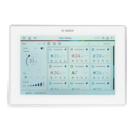
Page 20: Overview Dashboard
First steps Overview Dashboard Example for illustration purposes (changes possible) Description Description Header • Navigation elements on every page at the top edge of the screen • Access the main menu ( • Call up the page Dashboard ( • Go back to previous page ( •... -
Page 21: Changing The Keyboard Assignment
Following successful commissioning, we recommend saving british english &123 the settings on a USB stick and handing it to the customer ( operating instructions ACC MT). 0010036800-001 Fig. 22 Changing the keyboard assignment [1] Language symbol Air Center Control – 6720892132 (2021/10) -
Page 22: Help And Operation
Help and operation Help and operation Further explanations about the product and help can be called up directly at the central controller. Example of display (changes are possible) Description Description Initial Menu • Access the following via the Help menu item: –... -
Page 23: Environmental Protection And Disposal
Environmental protection and disposal Environmental protection and disposal Open Source Software Environmental protection is a fundamental corporate strategy Bosch Thermotechnik also uses Open Source Software to of the Bosch Group. control the products. The quality of our products, their economy and environmental... - Page 24 Bosch Commercial and Industrial Cotswold Way, Warndon, Worcester WR4 9SW Tel: 0330 123 3004 Email: [email protected] www.bosch-industrial.co.uk...