
Related Manuals for HP ProCurve 2824


Summary of Contents for HP ProCurve 2824
- Page 1 2800 series installation and getting started guide www.hp.com/go/hpprocurve...
- Page 3 HP ProCurve Switch 2800 Series Installation and Getting Started Guide...
- Page 4 The only warranties for HP products and services are set forth in the express warranty statements accompanying such products and services. Nothing herein should be construed as constituting an additional warranty.
-
Page 5: Table Of Contents
2. Installing or Removing mini-GBICs ......2-7 3. Verify the Switch Passes Self Test ......2-9 LED Behavior: . - Page 6 Downloading New Switch Software ......4-12 HP Customer Support Services ....... . 4-12 Terminal Configuration .
- Page 7 Switch Ports ........
- Page 8 Consideraciones sobre seguridad ......C-5 Safety Information (Japan) ........C-6 Safety Information (China) .
-
Page 9: Introducing The Switch
10/100/1000Base-T RJ-45 ports, four dual-personality ports—either auto- sensing 10/100/1000Base-T RJ-45 or mini-GBIC. The Switch 2800 Series devices can be connected to an HP ProCurve EPS/RPS (J8168A) and receive full redundant power from that unit. If the internal power supply in the switch fails, the EPS/RPS unit will immediately provide all the... - Page 10 In addition, the Switch 2800 Series devices offer full network management capabilities. This chapter describes the HP ProCurve Switch 2824 and Switch 2848, including: ■...
-
Page 11: Front Of The Switch
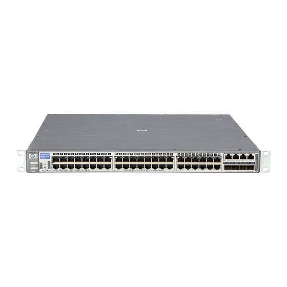
Console port** and indicator LEDs * 10/100/1000Base-T ports have the IEEE Auto MDI/MDI-X feature. Reset and Clear ** On the Switch 2848, the console port is located on the back of the unit. buttons Test, Fan and RPS Power Status LEDs... - Page 12 Front of the Switch ■ Four dual-personality ports. Use either the 10/100/1000Base-T RJ-45 connector, or install a supported HP ProCurve mini-GBIC for fiber-optic connections. The RJ-45 connectors support the IEEE Auto MDI/MDI-X feature, which means you can use either straight-through or crossover twisted-pair cables to connect any network device to the switch.
-
Page 13: Leds
(orange) Blinking* A fault has occurred on the switch, one of the switch ports, or the fan. The Status LED for the component with the fault will blink simultaneously. If just the Fault LED is blinking, the switch could be attached to an RPS but not receiving power. - Page 14 One of the unit’s fans has failed. The switch Fault LED will be blinking simultaneously. RPS Status Normal operation. An HP ProCurve EPS/RPS unit is connected and operating correctly. The EPS/RPS could be powering the unit - see table below.
-
Page 15: Led Mode Select Button And Indicator Leds
LED Mode Select Button and Indicator LEDs To optimize the amount of information displayed for each of the switch ports without overwhelming you with LEDs, the Switch 2800 Series devices use a single LED for each port. The operation of this LED is controlled by the LED Mode select button, and the current setting is indicated by the LED Mode indicator LEDs near the button. -
Page 16: Reset Button
0.5 sec.) • On = 1000 Mbps Reset Button This button is used to reset the switch while it is powered on. This action clears any temporary error conditions that may have occurred and executes the switch self test. Clear Button This button is used for these purposes: ■... -
Page 17: Back Of The Switch
Console Port This port is used to connect a console to the Switch 2800 Series devices by using the serial cable supplied with the switch. The console port is located on the front of the Switch 2824 and on the back of the Switch 2848. This connection is described under “Connect a Console to the Switch”... -
Page 18: Switch Features
MDI; if the switch detects that an end-node device is connected to the port, it configures the port as MDI-X. -
Page 19: Installing The Switch
Installing the Switch The HP ProCurve Switch 2800 Series devices are easy to install. They come with an accessory kit that includes the brackets for mounting the switch in a standard 19-inch telco rack, in an equipment cabinet, and with rubber feet that can be attached so the switch can be securely located on a horizontal surface. - Page 20 Installing the Switch Included Parts ■ Power cord, one of the following: Australia/New Zealand China Continental Europe Denmark Japan Switzerland United Kingdom/Hong Kong/Singapore United States/Canada/Mexico 8120-6803 8120-8377 8120-6802 8120-6806 8120-6804 8120-6807 8120-8709 8120-6805...
-
Page 21: Installation Procedures
PC to the switch’s console port. At this point, the switch is fully installed. See the rest of this chapter if you need more detailed information on any of these installation steps. -
Page 22: Installation Precautions
If your installation requires a different power cord than the one supplied ■ with the switch, be sure to use a power cord displaying the mark of the safety agency that defines the regulations for power cords in your country. -
Page 23: Prepare The Installation Site
Category 5 or better, 100-ohm UTP or shielded twisted-pair (STP) balanced cable. For 1000 Mbps (gigabit) operation, Category 5E cabling or better is recommended. Summary of Cable Types to Use With the Switch Length Limits Twisted-Pair Cables 100 meters Note: The Switch 2800 Series devices are compatible with the IEEE 802.3ab standard... - Page 24 Installation Location - Before installing the switch, plan its location and orientation relative to other devices and equipment: • In the front of the switch, leave at least 7.6 cm (3 inches) of space for the twisted-pair and fiber-optic cabling. •...
-
Page 25: Installing Or Removing Mini-Gbics
■ HP ProCurve Gigabit-LH-LC mini-GBIC (J4860A) C a u t i o n The HP ProCurve mini-GBICs are Class 1 laser devices. Avoid direct eye exposure to the beam coming from the transmit port. Installing the mini-GBICs: Hold the mini-GBIC by its sides and gently insert it into either of the slots on the switch until the mini-GBIC clicks into place. - Page 26 You should disconnect the network cable from the mini-GBIC before removing it from the switch. Depending on when you purchased your HP ProCurve mini-GBIC, it may have either of three different release mechanisms: a plastic tab on the bottom of the mini-GBIC, a plastic collar around the mini-GBIC, or a wire bail.
-
Page 27: Verify The Switch Passes Self Test
The Switch 2800 Series devices do not have a power switch. They are powered on when the power cord is connected to the switch and to a power source. For safety, the power outlet should be located near the switch installation. -
Page 28: Led Behavior
Power and Fault LEDs Switch 2848 Power and Fault LEDs When the switch is powered on, it performs its diagnostic self test. Self test takes approximately 50 seconds to complete. LED Behavior: During the self test: • Initially, all the status, LED Mode and port LEDs are on for most of the duration of the test. -
Page 29: Mount The Switch
Refer to chapter 4, “Troubleshooting” for diagnostic help. 4. Mount the Switch After the switch passes self test, you are ready to mount the switch in a stable location. The Switch 2800 Series devices can be mounted in these ways: ■... -
Page 30: Rack Mounting The Switch 2848
The mounting brackets have multiple mounting holes and can be rotated allowing for a wide variety of mounting options. These include mounting the switch so its front face is flush with the face of the rack, or mounting it in a more balanced position as shown in the illustration. - Page 31 Installing the Switch Installation Procedures Hold the switch with attached brackets up to the rack and move it vertically until rack holes line up with the bracket holes, then insert and tighten the four number 12-24 screws holding the brackets to the rack.
-
Page 32: Rack Mounting The Switch 2824
The mounting brackets have multiple mounting holes and can be rotated allowing for a wide variety of mounting options. These include mounting the switch so its front face is flush with the face of the rack, or mounting it in a more balanced position as shown in the illustration. - Page 33 (0.5-inch) pair on both sides of the rack Place the switch in the rack and lower it so the notches in the bottom of the bracket slide onto the screws, then tighten these screws. Lower switch with mounting...
- Page 34 Installing the Switch Installation Procedures Install the other number 12-24 screw into the upper hole in each bracket. Tighten these screws. 2-16...
-
Page 35: Horizontal Surface Mounting
Horizontal Surface Mounting Place the switch on a table or other horizontal surface. The switch comes with rubber feet in the accessory kit that can be used to help keep the switch from sliding on the surface. Attach the rubber feet to the four corners on the bottom of the switch within the embossed angled lines. -
Page 36: Connect The Network Cables
See the table on Network For mini-GBICs ports, and in general for all the switch ports, when a network cable from an active network device is connected to the port, the port LED for that port should go on. If the port LED does not go on when the network... -
Page 37: Optional) Connect A Redundant Power Supply To The Switch
AC power, or a fault condition. The EPS/RPS is an unmanaged power supply that only provides information by way of LEDs or through the port interfaces to attached devices. - Page 38 Power Message Connected Status Nothing Connected Not a valid state - should never happen Switch is connected, RPS is available but not required RPS is powering the connected device Blinking RPS port is in fault mode Blinking Switch is requesting power, RPS can not...
- Page 39 The EPS/RPS monitors the power signal from the switch by detecting that the EPS/RPS is connected to a switch with an EPS/RPS cable. When the power from the switch is no longer detected, the EPS/RPS will turn on and provide power to the switch within 1ms.
-
Page 40: Optional) Connect A Console To The Switch
■ the network, and a VT-100 terminal emulator. This method requires that you first configure the switch with an IP address and subnet mask by using either out-of-band console access or through DHCP/Bootp. For more information on IP addressing and on starting a Telnet session, see... -
Page 41: Direct Console Access
If you want to operate the console using a different configuration, make sure you change the settings on both the terminal and on the switch so they are compatible. Change the switch settings first, save your changes, then change the terminal settings, then reboot the switch and reestablish the console session. -
Page 42: Sample Network Topologies
Installing the Switch Sample Network Topologies Sample Network Topologies This section shows a few sample network topologies in which the Switch is implemented. For more topology information, see the HP network products World Wide Web site, As a Desktop Switch Power... -
Page 43: As A Segment Switch
LEGEND: Fast Ethernet cable The Switch also works well as a segment switch. That is, with its high performance, it can be used for interconnecting network segments—simply connect the network hubs that form those segments to the switch, or you can also connect other switches. - Page 44 Sample Network Topologies Because the Switch has the “IEEE Auto MDI/MDI-X” features, the connections between the switch and the hubs, and between the switch and end nodes or servers can be through category 5 “straight-through” or “crossover” twisted- pair cable. Category 3 or 4 cable can also be used if the connection is 10 Mbps only.
-
Page 45: Connecting To A Backbone Switch
The simpler desktop and segment networks shown in the previous two examples can easily be combined and expanded. For example, you could use an HP ProCurve Switch 5304xl to interconnect each of your smaller switched workgroups to form a larger switched network. All the devices in this network can communicate with each other. -
Page 46: Stacking The Switch
N o t e In the Backbone Switch illustration, the 1000 Mbps fiber-optic connection between the Switch 2824 and the Switch 5304xl is by way of a Gigabit-SX mini- GBIC installed in the Switch 2824 and connected to a Gigabit-SX Module in the Switch 5304xl. -
Page 47: The Switch In A Redundant Topology
100/1000Base-T Ports Link Mode Link Mode module J4821A J4821A HP ProCurve Switch 5308xl Fiber cable Installing the Switch module (all ports are HP Auto - MDIX) 100/1000Base-T Ports module 100/1000Base-T Ports module 100/1000Base-T Ports module 100/1000Base-T Ports module 100/1000Base-T Ports module... - Page 48 Installing the Switch Sample Network Topologies 2-30...
-
Page 49: Configuring The Switch
Configuring the Switch This chapter is a guide for using the console Switch Setup screen to quickly assign an IP (Internet Protocol) address and subnet mask to the switch, set a Manager password, and, optionally, configure other basic features. For more information on using the switch console and the other switch... -
Page 50: Using The Console Setup Screen
The quickest and easiest way to minimally configure the switch for manage- ment and password protection in your network is to use a direct console connection to the switch, start a console session, and access the Switch Setup screen. Using the method described in the preceding section, connect a terminal device to the switch and display the switch console command (CLI) prompt (the default display). - Page 51 Recommended; If you set IP Config to Manual, then enter an IP address Note: The IP address and subnet mask assigned for the switch must be compatible with the IP addressing used in your network. For more information on IP addressing, see the Management and Configuration Guide, which is on the Documentation CD-ROM that came with your switch.
-
Page 52: Where To Go From Here
The above procedure configures your switch with a Manager password, IP address, and subnet mask. As a result, with the proper network connections, you can now manage the switch from a PC equipped with Telnet or a web browser interface. -
Page 53: Using The Ip Address For Remote Switch Management
With the Switch 2800 Series devices, you can use the switch’s IP address to manage the switch from any PC that is on the same subnet as the switch. You can use either a Telnet session or a standard web browser to manage the switch. - Page 54 Management and Configuration Guide, which is on the Documentation CD-ROM that came with your switch. An extensive help system is also available for the web browser interface. To access the help system though the subnet on which the switch is installed you must have access to the internet.
-
Page 55: Troubleshooting
Connecting to devices that have a fixed full-duplex configuration. The RJ-45 ports are configured as “Auto”. That is, when connecting to attached devices, the switch will operate in one of two ways to determine the link speed and the communication mode (half duplex or full duplex): •... - Page 56 Basic Troubleshooting Tips Because the Switch 2800 Series devices behave in this way (in compli- ance with the IEEE 802.3 standard), if a device connected to the switch has a fixed configuration at full duplex, the device will not connect correctly to the switch.
- Page 57 CD-ROM that came with your switch. For more information on possible network problems and their solutions, refer to the technical note “Troubleshooting LAN Performance and Intermittent Connectivity Problems”, which can be found on the HP ProCurve web site, , in the Information Library section. http://www.hp.com/go/hpprocurve...
-
Page 58: Diagnosing With The Leds
Troubleshooting Diagnosing with the LEDs Diagnosing with the LEDs Table 3-1 shows LED patterns on the switch and the switch modules that indicate problem conditions. Check in the table for the LED pattern you see on your switch. Refer to the corresponding diagnostic tip on the next few pages. -
Page 59: Diagnostic Tips
Try power cycling the switch. If the fault indication reoccurs, the switch may have failed. hardware failure Call your HP-authorized LAN dealer, or use the electronic support services from HP to get has occurred. All assistance. See the Customer Support/Warranty booklet for more information. - Page 60 ➏ The network Try the following procedures: connection is not • For the indicated port, verify both ends of the cabling, at the switch and the connected working device, are connected properly. properly. • Verify the connected device and switch are both powered on and operating correctly.
- Page 61 Use the switch console to see if the port is part of a dynamic trunk (through the LACP improperly feature) or to see if Spanning Tree is enabled on the switch, and to see if the port may configured, or have been put into a “blocking”...
-
Page 62: Proactive Networking
Troubleshooting Proactive Networking Proactive Networking The HP ProCurve Switch 2800 Series devices have built-in management capabilities that proactively help you manage your network including: ■ finding and helping you fix the most common network error conditions (for example, faulty network cabling, and non-standard network topolo-... -
Page 63: Hardware Diagnostic Tests
Checking the Switch LEDs The self test passes if the Fault and Test LEDs on the front of the switch go off after approximately 50 seconds. If these LEDs stay on longer than 60 seconds or begin blinking, there may be a problem with the switch. -
Page 64: Testing Twisted-Pair Cabling
LAN adapters between which you can run a link-level test or Ping test through the switch, you can use this test to verify that the entire communication path between the two PCs is functioning correctly. See your LAN adapter documentation for more information on running a link test or Ping test. -
Page 65: Restoring The Factory Default Configuration
(usually disabling them) may result in network connectivity issues. If the switch has a valid configuration, and you are restoring the factory default settings for a reason other than configuration problems, you should save the switch configuration prior to performing the factory default reset. -
Page 66: Downloading New Switch Software
For more information, see the Management and Configuration Guide, which is on the Documentation CD- ROM that came with your switch. The new switch software would be available on the HP ProCurve web site, http://www.hp.com/go/hpprocurve HP Customer Support Services... -
Page 67: A Switch Specifications
Switch Specifications Physical Width: Depth: Height: Weight: Electrical The switch automatically adjusts to any voltage between 100-127 and 200-240 volts and either 50 or 60 Hz. AC voltage: Maximum current: Frequency range: Environmental Temperature: Relative humidity: (non-condensing) Maximum altitude: 2824 (J4903A) 2848 (J4904A) 44.3 cm (17.42 in) -
Page 68: Acoustic
■ UL 60950 Lasers The Gigabit-SX LC mini-GBIC, and the Gigabit-LX LC mini-GBIC, both of which can be installed in the Switch 2800 Series devices, are Class 1 Laser Products. Laser Klasse 1 These mini-GBICs comply with IEC 825-2: 1993. -
Page 69: B Switch Ports And Network Cables
N o t e Incorrectly wired cabling is the most common cause of problems for LAN communications. HP recommends that you work with a qualified LAN cable installer for assistance with your cabling requirements. Switch Ports The fixed RJ-45 10/100/1000Base-T ports on the switch accept 100-ohm unshielded and shielded twisted-pair cable with RJ-45 connectors as described on the next page. - Page 70 Equal-Level Far-End Crosstalk (ELFEXT) and Return Loss. When testing your cabling, be sure to include the patch cables that connect the switch and other end devices to the patch panels on your site. The patch cables are frequently overlooked when testing cable and they must also comply with the cabling standards.
-
Page 71: Mode Conditioning Patch Cord For Gigabit-Lx
If you experience a high number of transmission errors on the Gigabit-LX ports, usually CRC or FCS errors, you may need to install one of these patch cords between the Gigabit-LX port in your switch and your multimode fiber- optic network cabling, and between the Gigabit-LX transmission device and the network cabling at the other end of the multimode fiber-optic cable run. -
Page 72: Installing The Patch Cord
Recommended Patch Cords Hewlett-Packard maintains a list of recommended Mode Conditioning Patch Cords that have been tested and verified to operate correctly with the HP ProCurve Gigabit-LX Transceiver and HP ProCurve Gigabit-LX LC mini-GBIC. The list is on the HP ProCurve web site, Technical Support section. -
Page 73: Twisted-Pair Cable/Connector Pin-Outs
MDI port. If you connect it to an end node, such as a server or PC, which typically have MDI ports, the Switch 2800 Series device’s port operates as an MDI-X port. In all cases, you can use standard “straight through”... -
Page 74: Straight-Through Twisted-Pair Cable For 10 Mbps Or 100 Mbps Network Connections
Straight-Through Twisted-Pair Cable for 10 Mbps or 100 Mbps Network Connections Because of the MDI/MDI-X operation of the 10/100 ports on the switch, for all network connections, to PCs, servers or other end nodes, or to hubs or other switches, you can use “straight-through” cables. -
Page 75: Crossover Twisted-Pair Cable For 10 Mbps Or 100 Mbps Network Connection
Crossover Twisted-Pair Cable for 10 Mbps or 100 Mbps Network Connection The MDI/MDI-X operation of the 10/100 ports on the switch also allows you to use “crossover” cables for all network connections, to PCs, servers or other end nodes, or to hubs or other switches. -
Page 76: Straight-Through Twisted-Pair Cable For 1000 Mbps Network Connections
Switch Ports and Network Cables Twisted-Pair Cable/Connector Pin-Outs Straight-Through Twisted-Pair Cable for 1000 Mbps Network Connections 1000Base-T connections require that all four pairs of wires be connected. Cable Diagram N o t e Pins 1 and 2 on connector “A” must be wired as a twisted pair to pins 1 and 2 on connector “B”. -
Page 77: C Safety And Emc Regulatory Statements
These products do not have a power switch; they are powered on when the power cord is plugged in. Documentation reference symbol. If the product is marked with this symbol, refer to the product documentation to get more information about the product. -
Page 78: Informations Concernant La Sécurité
Safety and EMC Regulatory Statements Informations concernant la sécurité Informations concernant la sécurité WARNING CAUTION Cet appareil est un produit de classe I et possède une borne de mise à la terre. La source d'alimentation principale doit être munie d'une prise de terre de sécurité installée aux bornes du câblage d'entrée, sur le cordon d'alimentation ou le cordon de raccordement fourni avec le produit. -
Page 79: Hinweise Zur Sicherheit
Hinweise zur Sicherheit Symbol für Dokumentationsverweis. Wenn das Produkt mit diesem Symbol markiert ist, schlagen Sie bitte in der Produktdokumentation nach, um mehr Informationen über das Produkt zu erhalten. WARNING Eine WARNING in der Dokumentation symbolisiert eine Gefahr, die Verletzungen oder sogar Todesfälle verursachen kann. CAUTION CAUTION in der Dokumentation symbolisiert eine Gefahr, die dis Gerät beschädigen kann. -
Page 80: Considerazioni Sulla Sicurezza
Safety and EMC Regulatory Statements Considerazioni sulla sicurezza Considerazioni sulla sicurezza WARNING CAUTION Questo prodotto è omologato nella classe di sicurezza I ed ha un terminale protettivo di collegamento a terra. Dev'essere installato un collegamento a terra di sicurezza, non interrompibile che vada dalla fonte d'alimentazione principale ai terminali d'entrata, al cavo d'alimentazione oppure al set cavo d'alimentazione fornito con il prodotto. -
Page 81: Consideraciones Sobre Seguridad
Consideraciones sobre seguridad Símbolo de referencia a la documentación. Si el producto va marcado con este símbolo, consultar la documentación del producto a fin de obtener mayor información sobre el producto. WARNING Una WARNING en la documentación señala un riesgo que podría resultar en lesiones o la muerte. -
Page 82: Safety Information (Japan
Safety and EMC Regulatory Statements Safety Information (Japan) Safety Information (Japan) -
Page 83: Safety Information (China
Safety and EMC Regulatory Statements Safety Information (China) Safety Information (China) -
Page 84: Emc Regulatory Statements
Safety and EMC Regulatory Statements EMC Regulatory Statements EMC Regulatory Statements U.S.A. FCC Class A This equipment has been tested and found to comply with the limits for a Class A digital device, pursuant to Part 15 of the FCC Rules. These limits are designed to provide reasonable protection against interference when the equipment is operated in a commercial environment. -
Page 85: Korea
Safety and EMC Regulatory Statements EMC Regulatory Statements Korea Taiwan... -
Page 86: European Community
Hewlett-Packard Company Manufacturer's Address: 8000 Foothills Blvd Roseville, CA 95747-5502 U.S.A. declares that the product: Product Name: HP ProCurve Switch 2824, HP ProCurve Switch 2848 Model Number: J4903A, J4904A Accessories: J4858A, J4859A, J4860A Regulatory Model Number: RSVLC-0207 conforms to the following Product Specifications:... - Page 87 1000Base-T connections, length limitations … 2-5 ports, cables used with … 2-5 AC power connector location on back of switch … 1-9 Act LED … 1-5, 1-8 auto MDI/MDI-X operation … B-6, B-8 MDIX feature … B-5 back of switch description …...
- Page 88 … 3-2 restoring factory defaults … 1-8, 4-11 subnet mask … 3-3 Switch Setup screen … 3-2 connecting the switch to a power source … 2-17 connecting the switch to an EPS/RPS … 2-21 connector specifications … A-2 console checking messages during troubleshooting …...
- Page 89 … 3-1 in-band console access types of … 2-22 included parts … 2-1 installation connecting the switch to a power source … 2-17 horizontal surface mounting … 2-17 location considerations … 2-6 network cable requirements … 2-5 precautions … 2-4 rack or cabinet mounting …...
- Page 90 … 1-3 standards compliance … A-2 types of … 1-3, 2-5 non-standard network cables, effects … 4-2 out-of-band console access … 3-5 parts, included with the switch … 2-1 password configuring … 3-2 passwords deleting with the Clear button … 3-4 if you lose the password …...
- Page 91 … B-6, B-8 subnet mask configuring … 3-3 summary of cables used with the switch … 2-5 of switch installation … 2-3 switch connecting to a power source … 2-17 description … 1-1 downloading new software … 4-12 electrical specifications …...
- Page 92 Technical information in this document is subject to change without notice. ©Copyright 2002, 2003 Hewlett-Packard Development Company, L.P. Reproduction, adaptation, or translation without prior written permission is prohibited except as allowed under the copyright laws. Printed in Singapore August 2003 Manual Part Number 5990-3093 *5990-3093*...