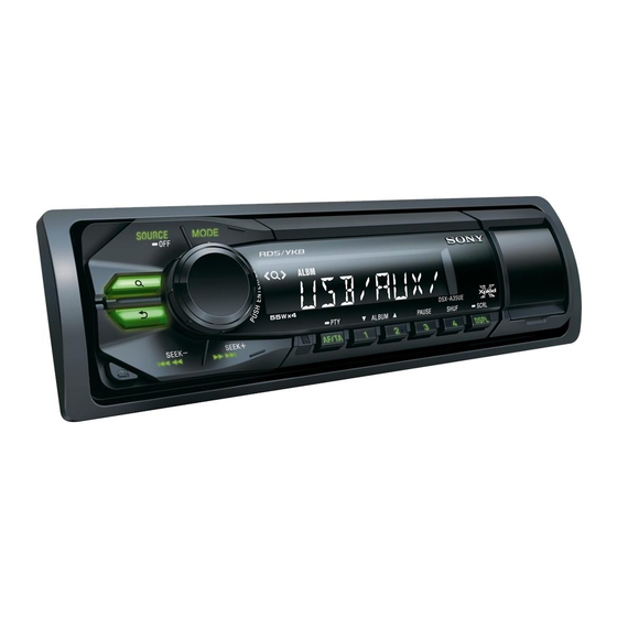
Sony DSX-A50BT Service Manual
Fm/mw/lw digital media player
Hide thumbs
Also See for DSX-A50BT:
- Operating instructions manual (224 pages) ,
- Installation/connections (2 pages) ,
- Operating instructions manual (80 pages)
Table of Contents
Quick Links
SERVICE MANUAL
Ver. 1.0 2012.03
• This model is not equipped with a mechanism deck.
Tuner section
Tuner section
(AEP and UK models)
(E and Indian models)
FM
FM
Tuning range: 87.5 – 108.0 MHz
Tuning range:
Antenna (aerial) terminal:
External antenna (aerial) connector
Intermediate frequency: 25 kHz
Usable sensitivity: 8 dBf
FM tuning step:
Selectivity: 75 dB at 400 kHz
Signal-to-noise ratio: 80 dB (stereo)
Antenna (aerial) terminal:
Separation: 50 dB at 1 kHz
Frequency response: 20 – 15,000 Hz
Intermediate frequency: 25 kHz
Usable sensitivity: 8 dBf
MW/LW
Selectivity: 75 dB at 400 kHz
Tuning range:
Signal-to-noise ratio: 80 dB (stereo)
MW: 531 – 1,602 kHz
Separation: 50 dB at 1 kHz
LW: 153 – 279 kHz
Frequency response: 20 – 15,000 Hz
Antenna (aerial) terminal:
AM
External antenna (aerial) connector
Intermediate frequency:
Tuning range:
9,124.5 kHz or 9,115.5 kHz/4.5 kHz
Sensitivity: MW: 26 µV, LW: 45 µV
AM tuning step:
Antenna (aerial) terminal:
Intermediate frequency:
Sensitivity: 26 µV
9-893-450-01
Sony Corporation
2012C33-1
©
2012.03
Published by Sony Techno Create Corporation
SPECIFICATIONS
87.5 – 108.0 MHz (at 50 kHz step)
87.5 – 108.0 MHz (at 100 kHz step)
87.5 – 107.9 MHz (at 200 kHz step)
50 kHz/100 kHz/200 kHz switchable
External antenna (aerial) connector
531 – 1,602 kHz (at 9 kHz step)
530 – 1,710 kHz (at 10 kHz step)
9 kHz/10 kHz switchable
External antenna (aerial) connector
9,124.5 kHz or 9,115.5 kHz/4.5 kHz
(at 9 kHz step)
9,115 kHz or 9,125 kHz/5 kHz (at 10 kHz step)
DSX-A50BT
USB Player section
Interface: USB (Full-speed)
Maximum current: 500 mA
Wireless Communication
Communication System:
Bluetooth Standard version 2.1 + EDR
Output:
Bluetooth Standard Power Class 2 (Max. +4
dBm)
Maximum communication range:
Line of sight approx. 10 m (33 )*
1
Frequency band:
2.4 GHz band (2.4000 – 2.4835 GHz)
Modulation method: FHSS
Compatible Bluetooth Pro les*
2
:
A2DP (Advanced Audio Distribution Pro le)
1.2
AVRCP (Audio Video Remote Control Pro le)
1.3
HFP (Handsfree Pro le) 1.5
PBAP (Phone Book Access Pro le)
*1
e actual range will vary depending on
factors such as obstacles between devices,
magnetic elds around a microwave oven,
static electricity, reception sensitivity, antenna
(aerial)'s performance, operating system,
so ware application, etc.
*2 Bluetooth standard pro les indicate the
purpose of Bluetooth communication
between devices.
FM/MW/LW DIGITAL MEDIA PLAYER
FM/AM DIGITAL MEDIA PLAYER
AEP Model
UK Model
E Model
Power ampli er section
Output: Speaker outputs
Speaker impedance: 4 – 8 ohms
Maximum power output: 50 W u 4 (at 4 ohms)
General
Outputs:
Audio outputs terminal (front/rear)
AEP and UK models:
Power antenna (aerial) relay control terminal
Power ampli er control terminal
E and Indian models:
Power antenna (aerial)/Power ampli er control
terminal (REM OUT)
Inputs:
Remote controller input terminal
Antenna (aerial) input terminal
AUX input jack (stereo mini jack)
USB signal input connector
Power requirements: 12 V DC car battery
(negative ground (earth))
Dimensions: Approx. 178 u 50 u 120 mm
1
7
(7
/
u 2 u 4
/
in) (w/h/d)
8
8
Mounting dimensions: Approx. 182 u 53 u 103 mm
1
1
1
(7
/
u 2
/
u 4
/
in) (w/h/d)
4
8
8
Mass: Approx. 0.7 kg (1 lb 9 oz)
Supplied accessories:
Remote commander: RM-X231
Parts for installation and connections (1 set)
Your dealer may not handle some of the above
listed accessories. Please ask the dealer for
detailed information.
Design and speci cations are subject to change
without notice.
AEP, UK models
E, Indian models
Table of Contents

Related Manuals for Sony DSX-A50BT


Summary of Contents for Sony DSX-A50BT
- Page 1 Design and speci cations are subject to change without notice. AEP, UK models FM/MW/LW DIGITAL MEDIA PLAYER E, Indian models FM/AM DIGITAL MEDIA PLAYER 9-893-450-01 Sony Corporation 2012C33-1 © 2012.03 Published by Sony Techno Create Corporation...
-
Page 2: Table Of Contents
DSX-A50BT e Bluetooth word mark and logos are TABLE OF CONTENTS owned by the Bluetooth SIG, Inc. and any use of such marks by Sony Corporation is SERVICING NOTES ..........under license. Other trademarks and trade names are those of their respective owners. - Page 3 DSX-A50BT SECTION 1 SERVICING NOTES UNLEADED SOLDER IMPORTANT NOTE OF “INITIALIZING” Boards requiring use of unleaded solder are printed with the lead- The purpose of “Bluetooth Initialize” is to initialize the Bluetooth free mark (LF) indicating the solder contains no lead.
- Page 4 DSX-A50BT NOTE THE MAIN BOARD OR SYSTEM CONTROLLER • Method of operation by remote commander (IC101) REPLACING When the MAIN board or system controller (IC101) is replaced, the destination setting is necessary. 1. Destination Setting Set destination according to the procedure below.
- Page 5 2. Preparation “HF” icon ( ) lights. • Confi rm the setting of the DSX-A50BT, and notate it. 5. Confi rm the connection continues even if the distance of the • Press the [CALL] button and rotate the control dial until cellular phone and this unit is separated by about 5 m.
- Page 6 DSX-A50BT SECTION 2 This section is extracted GENERAL from instruction manual. (AEP and UK models) FRONT AUDIO OUT REAR AUDIO OUT Speaker impedance: 4 – 8 ohms × 4 Lautsprecherimpedanz: 4 – 8 Ohm × 4 Impédance des haut-parleurs : 4 – 8 ohms × 4 Impedenza di usori: 4 –...
- Page 7 Raadpleeg in dat geval de Fusibile (10 A) angegeben. le plus proche. caso, rivolgersi al più vicino Sony-dealer bij u in de buurt. Wenn die Sicherung durchbrennt, rivenditore Sony. überprüfen Sie den Stromanschluss und tauschen die Sicherung aus. the car without ACC position...
- Page 8 DSX-A50BT (E and Indian models) FRONT AUDIO OUT REAR AUDIO OUT Speaker impedance: 4 – 8 ohms × 4 Impedancia de los altavoces: de 4 a 8 Ω × 4 RCA pin cord (not supplied). Cable con terminales RCA (no suministrado).
- Page 9 You may not be able to install this unit in some makes of Montaje de la unidad en un fundirse después de sustituirlo, es Japanese cars. In such a case, consult your Sony dealer. Notes on the tuning step automóvil japonés...
-
Page 10: Disassembly
DSX-A50BT SECTION 3 DISASSEMBLY • This set can be disassembled in the order shown below. 3-1. DISASSEMBLY FLOW FRONT PANEL SECTION Note: Illustration of disassembly is omitted. 3-2. FUSE (BLADE TYPE) (AUTO FUSE) (10A/32V) (FU101), COVER (Page 10) 3-3. SUB PANEL BLOCK (Page 11) 3-4. -
Page 11: Sub Panel Block
DSX-A50BT 3-3. SUB PANEL BLOCK 1 tape ‡ :LUH VHWWLQJ 3 two claws connector BT board 5 sub panel block (CN1004) MAIN board Note 1: Where USB cover is closed, remove the sub panel block. 3 two claws tape 4 two claws... -
Page 12: Main Board (With Bt Board)
DSX-A50BT 3-4. MAIN BOARD (WITH BT BOARD) 2 screw ‡ :LUH VHWWLQJ (PTT2.6 u 8) lead wire with connector connector BT board (CN1006) 3 two ground point screws MAIN board (PTT2.6 u 6) 2 screw (PTT2.6 u 8) 4 MAIN board... -
Page 13: Test Mode
DSX-A50BT SECTION 4 TEST MODE SETTING THE TEST MODE Setting method: 1. Press the [SOURCE/OFF] button for 1 second to turn the pow- er off. 2. Press the [4] o [5] (remote commander) o [1] buttons se- quentially (the [1] button is pressed for two seconds). -
Page 14: Diagrams
DSX-A50BT SECTION 5 DIAGRAMS 5-1. BLOCK DIAGRAM - MAIN Section - J301 CN201 FRONT AUDIO OUT R-CH REAR UDP1 AUDIO OUT R-CH D– UDM1 VBUS USB_VBUS USB CONTROLLER, CENTER VOLTAGE INPUT SELECTOR, POWER AMP +8.5V GENERATOR J304 IC304 CN102 (1/2) -
Page 15: Display/Power Supply Section
DSX-A50BT 5-2. BLOCK DIAGRAM - DISPLAY/POWER SUPPLY Section - SYSTEM CONTROLLER IC101 (2/2) REGULATOR CN102 (2/2) IC401 XOUT RESET X101 +3.3V SIGNAL 32.768kHz RESET 10 VDD (BACKUP5V) REGULATOR GENERATOR IC102 IC105 OSCOUT FU101 X102 VCC1 9 BU +3.3V LIQUID CRYSTAL DISPLAY LIQUID CRYSTAL DISPLAY DRIVER 7.92MHz... - Page 16 DSX-A50BT THIS NOTE IS COMMON FOR PRINTED WIRING BOARDS AND SCHEMATIC DIAGRAMS. • Waveforms (In addition to this, the necessary note is printed in each block.) – MAIN Board – – KEY Board – For Printed Wiring Boards. For Schematic Diagrams.
-
Page 17: Schematic Diagram - Main Section (1/3)
DSX-A50BT 5-3. SCHEMATIC DIAGRAM - MAIN Section (1/3) - • See page 26 for IC Block Diagrams. MAIN BOARD (1/3) IC B/D IC304 POWER AMP J301 IC304 LV47011P-E FRONT AUDIO OUT CN102 REAR (E, IND) AUDIO OUT C319 FRONT LCH+... -
Page 18: Schematic Diagram - Main Section (2/3)
DSX-A50BT • See page 16 for waveforms. • See page 26 for IC Block Diagrams. • See page 27 for IC Pin Function Description. 5-4. SCHEMATIC DIAGRAM - MAIN Section (2/3) - MAIN BOARD (2/3) R804 R194 100k C252 R303... -
Page 19: Schematic Diagram - Main Section (3/3)
DSX-A50BT • See page 16 for waveforms. • See page 26 for IC Block Diagrams. • See page 27 for IC Pin Function Description. 5-5. SCHEMATIC DIAGRAM - MAIN Section (3/3) - ANTENNA BOARD (PA TTERN ANTENNA) CN001 MIC201 BOARD... -
Page 20: Printed Wiring Board - Main Section (1/2) (Aep And Uk Models)
DSX-A50BT 5-6. PRINTED WIRING BOARD - MAIN Section (1/2) (AEP and UK models) - • : Uses unleaded solder. MAIN BOARD (COMPONENT SIDE) CAM251 (CHASSIS) C314 R331 R328 C321 C327 C313 R329 R333 C310 R334 C320 R325 R326 IC301 R330... -
Page 21: Printed Wiring Boards - Main Section (2/2) (Aep And Uk Models)
DSX-A50BT 5-7. PRINTED WIRING BOARDS - MAIN Section (2/2) (AEP and UK models) - • : Uses unleaded solder. J301 FRONT REAR AUDIO OUT AUDIO OUT MAIN BOARD (CONDUCTOR SIDE) J101 J303 (REMOTE IN) FU101 (ANTENNA IN) RL– GRN/BLK FL–... -
Page 22: Printed Wiring Board - Main Section (1/2) (E And Indian Models)
DSX-A50BT 5-8. PRINTED WIRING BOARD - MAIN Section (1/2) (E and Indian models) - • : Uses unleaded solder. MAIN BOARD (COMPONENT SIDE) CAM251 (CHASSIS) C314 R331 R328 C321 C327 C313 R329 R333 C310 R334 C320 R325 R326 IC301 R330... -
Page 23: Printed Wiring Boards - Main Section (2/2) (E And Indian Models)
DSX-A50BT 5-9. PRINTED WIRING BOARDS - MAIN Section (2/2) (E and Indian models) - • : Uses unleaded solder. J301 FRONT REAR AUDIO OUT AUDIO OUT MAIN BOARD (CONDUCTOR SIDE) J101 J303 FU101 (REMOTE IN) (ANTENNA IN) WHT/BLK FRONT LCH (–) -
Page 24: 5-10. Printed Wiring Board - Key Board
DSX-A50BT 5-10. PRINTED WIRING BOARD - KEY Board - • : Uses unleaded solder. LED906, S906 KEY BOARD (COMPONENT SIDE) CALL S906 LED907, S901 LED907 LED906 S901 R958 SOURCE R920 R915 R913 R957 R914 R906 R905 R954 R902 R901 LED902, S905... -
Page 25: 5-11. Schematic Diagram - Key Board
DSX-A50BT 5-11. SCHEMATIC DIAGRAM - KEY Board - • See page 16 for waveforms. • See page 26 for IC Block Diagrams. KEY BOARD CN001 R920 P ANEL_SW LED902 LED906 LCD_CLK R913 SCM015B17TT86P R955 SCM015B17TT86P LCD_CE SEEK+ CALL MAIN LCD_DA T A... - Page 26 DSX-A50BT • IC Block Diagrams IC501 OZ529IGN-A1-TR – MAIN Board – BST 1 VREF IC304 LV47011P-E IC102, 601 MM1836A33NRE OSCILLATOR TAB 1 LX 2 REFERENCE PWR GND2 2 GENERATOR OVER CURRENT CONT 1 BIAS CURRENT PROTECTION LIMIT OUT 2– 3...
- Page 27 DSX-A50BT • IC Pin Function Description MAIN BOARD IC101 R5F3650KCDZ98FB (SYSTEM CONTROLLER) Pin No. Pin Name Description NOSE_SW Front panel remove/attach detection signal input terminal “L”: front panel is attached SIRCS Remote control signal input from the remote control receiver...
- Page 28 DSX-A50BT Pin No. Pin Name Description 67 to 71 Not used AMP_REM Amplifi er remote output on/off control signal output terminal “H”: output on SYS_EN System power on/off control signal output to the DC/DC converter “H”: power on AUDIO_EN Power supply on/off control signal output terminal for audio section “H”: power on...
- Page 29 DSX-A50BT MAIN BOARD IC201 LC786800E-00US-H (USB CONTROLLER, INPUT SELECTOR, AUDIO DSP, ELECTRICAL VOLUME) Pin No. Pin Name Description LFOUT Audio signal (front L-ch) output terminal LROUT Audio signal (rear L-ch) output terminal LVRIN Audio signal (L-ch) input terminal DACOUT_L Audio signal (L-ch) output terminal...
- Page 30 DSX-A50BT Pin No. Pin Name Description AFILT Charge pump output terminal (for audio PLL) VVDD2 Power supply terminal (+3.3V) (for audio PLL) VVDD3 Power supply terminal (+3.3V) (for system PLL) DVDD Power supply terminal (+3.3V) (for digital system) DVSS Ground terminal (for digital system)
-
Page 31: Exploded Views
DSX-A50BT SECTION 6 EXPLODED VIEWS Note: • -XX and -X mean standardized parts, so • The mechanical parts with no reference • Abbreviation they may have some difference from the number in the exploded views are not sup- : Indian model original one. -
Page 32: Front Panel Section
DSX-A50BT 6-2. FRONT PANEL SECTION KEY board S907 CCB1 IC902 LCD901 not supplied not supplied not supplied not supplied not supplied Ref. No. Part No. Description Remark Ref. No. Part No. Description Remark X-2582-973-1 KNOB (VOL) (SV) ASSY 4-290-177-01 SCREW (+B P-TITE M2) -
Page 33: Electrical Parts List
DSX-A50BT SECTION 7 ANTENNA ELECTRICAL PARTS LIST Note: • Due to standardization, replacements in • CAPACITORS When indicating parts by reference num- the parts list may be different from the uF: —F ber, please include the board name. parts specifi ed in the diagrams or the com- •... - Page 34 DSX-A50BT MAIN Ref. No. Part No. Description Remark Ref. No. Part No. Description Remark R935 1-216-809-11 METAL CHIP 1/10W C218 1-126-210-21 ELECT CHIP 220uF R936 1-216-809-11 METAL CHIP 1/10W R938 1-216-295-91 SHORT CHIP C219 1-125-777-11 CERAMIC CHIP 0.1uF R950 1-216-809-11...
- Page 35 DSX-A50BT MAIN Ref. No. Part No. Description Remark Ref. No. Part No. Description Remark C336 1-162-964-11 CERAMIC CHIP 0.001uF CN201 1-843-174-11 USB CONNECTOR ( ) C337 1-165-908-11 CERAMIC CHIP 1uF < DIODE > C338 1-162-964-11 CERAMIC CHIP 0.001uF C339 1-165-908-11...
- Page 36 DSX-A50BT MAIN Ref. No. Part No. Description Remark Ref. No. Part No. Description Remark Q104 8-729-620-13 TRANSISTOR 2SC4154TP-1EF R189 1-218-941-81 METAL CHIP 1/16W Q106 8-729-620-07 TRANSISTOR 2SC3052EF-T1-LEF R190 1-218-941-81 METAL CHIP 1/16W Q109 6-552-410-01 TRANSISTOR DRA5114E0L R191 1-218-941-81 METAL CHIP...
- Page 37 DSX-A50BT MAIN Ref. No. Part No. Description Remark Ref. No. Part No. Description Remark R310 1-218-966-11 METAL CHIP 1/16W R607 1-218-971-11 METAL CHIP 1/16W R311 1-218-965-11 METAL CHIP 1/16W R608 1-218-969-11 METAL CHIP 1/16W R312 1-216-845-11 METAL CHIP 100K 1/10W...
- Page 38 DSX-A50BT Ref. No. Part No. Description Remark PARTS FOR INSTALLATION AND CONNECTIONS ************************************** (E, IND) X-2548-178-1 FRAME ASSY, FITTING 1-839-372-11 CONNECTION CORD FOR AUTOMOBILE (POWER) (E, IND) 1-839-387-11 CONNECTION CORD (ISO) (POWER) (AEP, UK) 1-465-459-51 ADAPTOR, ANTENNA (AEP, UK) 4-276-003-01...
- Page 39 DSX-A50BT MEMO...
- Page 40 DSX-A50BT REVISION HISTORY Checking the version allows you to jump to the revised page. Also, clicking the version at the top of the revised page allows you to jump to the next revised page. Ver. Date Description of Revision 2012.03...