
Related Manuals for Omron CS1W-ETN11


Summary of Contents for Omron CS1W-ETN11
- Page 1 Cat. No. W343-E1-07 SYSMAC CS/CJ Series CS1W-ETN01 (10Base-5) CS1W-ETN11 (10Base-T) CJ1W-ETN11 (10Base-T) Ethernet Units OPERATION MANUAL...
- Page 2 CS1W-ETN01 (10Base-5) CS1W-ETN11 (10Base-T) CJ1W-ETN11 (10Base-T) Ethernet Units Operation Manual Revised January 2008...
- Page 4 OMRON. No patent liability is assumed with respect to the use of the information contained herein. Moreover, because OMRON is con- stantly striving to improve its high-quality products, the information contained in this manual is subject to change without notice.
-
Page 6: Table Of Contents
TABLE OF CONTENTS PRECAUTIONS ....... . xvii Intended Audience ..........xviii General Precautions . - Page 7 TABLE OF CONTENTS SECTION 4 System Setup and Memory Allocations....Allocated Words ..........CPU Bus Unit System Setup .
- Page 8 TABLE OF CONTENTS SECTION 10 Troubleshooting ....... . 10-1 Troubleshooting with Indicators ........10-2 Error Status .
- Page 10 About this Manual: This manual describes the installation and operation of the SYSMAC CS-series CS1W-ETN01 (10Base-5) and CS1W-ETN11 (10Base-T) Ethernet Units and the CJ-series CJ1W-ETN11 (10Base-T) Ethernet Unit, and includes the sections described on the next page. An Ethernet Unit is classified and treated as a CPU Bus Unit in PC processing.
- Page 11 Describes the use of Serial Communications Units and Boards to per- CS1W-SCB21-V1/41-V1, CS1W-SCU21 form serial communications with external devices, including the usage CJ1W-CSU41 of standard system protocols for OMRON products. Serial Communications Boards and Serial Communications Units Operation Manual This manual contains the following sections.
- Page 12 WHETHER SUCH CLAIM IS BASED ON CONTRACT, WARRANTY, NEGLIGENCE, OR STRICT LIABILITY. In no event shall the responsibility of OMRON for any act exceed the individual price of the product on which liability is asserted. IN NO EVENT SHALL OMRON BE RESPONSIBLE FOR WARRANTY, REPAIR, OR OTHER CLAIMS...
- Page 13 Application Considerations SUITABILITY FOR USE OMRON shall not be responsible for conformity with any standards, codes, or regulations that apply to the combination of products in the customer's application or use of the products. At the customer's request, OMRON will provide applicable third party certification documents identifying ratings and limitations of use that apply to the products.
- Page 14 Performance data given in this manual is provided as a guide for the user in determining suitability and does not constitute a warranty. It may represent the result of OMRON's test conditions, and the users must correlate it to actual application requirements. Actual performance is subject to the OMRON Warranty and Limitations of Liability.
- Page 16 PRECAUTIONS This section provides general precautions for using the CS/CJ-series Programmable Controllers (PCs) and related devices. The information contained in this section is important for the safe and reliable application of Programmable Controllers. You must read this section and understand the information contained before attempting to set up or operate a PC system.
-
Page 17: Intended Audience
It is extremely important that a PC and all PC Units be used for the specified purpose and under the specified conditions, especially in applications that can directly or indirectly affect human life. You must consult with your OMRON representative before applying a PC System to the above-mentioned applica- tions. -
Page 18: Operating Environment Precautions
Operating Environment Precautions !Caution Execute online edit only after confirming that no adverse effects will be caused by extending the cycle time. Otherwise, the input signals may not be readable. Operating Environment Precautions !Caution Do not operate the control system in the following places: •... - Page 19 Application Precautions • Mounting or dismounting I/O Units, CPU Units, Inner Boards, or any other Units. • Assembling the Units. • Setting DIP switches or rotary switches. • Connecting cables or wiring the system. !Caution Failure to abide by the following precautions could lead to faulty operation of the PC or the system, or could damage the PC or PC Units.
-
Page 20: Conformance To Ec Directives
Concepts EMC Directives OMRON devices that comply with EC Directives also conform to the related EMC standards so that they can be more easily built into other devices or the overall machine. The actual products have been checked for conformity to EMC standards (see the following note). -
Page 22: Features And System Configuration
SECTION 1 Features and System Configuration This section introduces the overall structure of an Ethernet network, outlines the features of the Ethernet Unit, describes the communications protocols used by an Ethernet network, and provides basic precautions for use of an Ethernet network. Features . -
Page 23: Features
FINS Message The Ethernet Unit also supports FINS message communications, OMRON’s Communications standard communications service, so other OMRON PCs can be accessed by (FINS Communications using SEND(090), RECV(098), and CMND(490) instructions in ladder pro- Service Using UDP/IP) grams. In addition, the FINS gateway function can be used to allow access to other PCs on not only the same Ethernet network but also on other networks such as Controller Link and SYSMAC Link. -
Page 24: System Configuration
10Base-5 coaxial cable Integral multiples of 2.5 m (or 10Base-T twisted-pair cable) Ground Transceiver 50 m max. CVM1/CV-series CJ-series CS-series PC CS-series Transceiver cable CJ1W-ETN11 CS1W-ETN11 Ethernet Unit 100 m max. Ethernet Unit CS-series (10Base-T) (10Base-T) CS1W-ETN01 Ethernet Unit CS-series CJ-series (10Base-5) -
Page 25: Devices Required In A Network
Devices Required in a Network Section 1-3 Configuration With Use repeaters to extend the distance between nodes or to increase the num- Segment Extension ber of connected nodes. 10Base-5 Repeater Node Node Node Node Devices Required in a Network 1-3-1 10Base-5 Ethernet Unit The basic configuration of a 10Base-5 Ethernet System consists of a single coaxial cable together with the transceivers, transceiver cables, nodes, and so... -
Page 26: 10Base-T Ethernet Unit
1-3-2 10Base-T Ethernet Unit The basic configuration of a 10Base-T Ethernet System consists of one hub to which nodes are attached in star form through twisted-pair cable. CS1W-ETN11/CJ1W-ETN11 Ethernet Units Twisted-pair cables 100 m max. 100 m max. The devices shown in the following table must be obtained to configure a net- work using a 10Base-T Ethernet Unit, so prepare them in advance. -
Page 27: Related Programming Devices
Related Programming Devices Section 1-4 Related Programming Devices The Ethernet Unit functions as a node on the Ethernet network. The basic set- tings for operation are made in the CPU Bus Unit System Setup in the CS/CJ- series CPU Unit. Use the CX-Programmer to make the settings. Personal computer running Windows CX-Programmer CPU Bus Unit... -
Page 28: Specifications
2.5 A max. (24-VDC startup time of 5 ms) Permissible voltage fluctuation range: 20.4 to 26.4 VDC (24 VDC –15% to +10%) Recommended power supply: OMRON S82J-series Power supply to transceiver Capacity: 0.4 A at 12 V Voltage fluctuation range: 13.05 to 14.48 VDC... - Page 29 Specifications Section 1-5 CJ-series Ethernet Units Item Specifications Model number CJ1W-ETN11 Type 10Base-T Applicable PCs CJ-series PCs Unit classification CJ-series CPU Bus Unit Mounting location CPU Rack or Expansion Rack Number of Units that can be mounted 4 max. (including Expansion Racks) Transfer Media access method CSMA/CD...
- Page 30 Specifications Section 1-5 Dimensions CS1W-ETN01 (16.5 including cover) (Unit: mm) CS1W-ETN11 (Unit: mm)
-
Page 31: Software Configuration
Software Configuration Section 1-6 CJ1W-ETN11 ETN11 ERC SD ERH TCP FTP UNIT NODE ETHERNET (Unit: mm) Software Configuration The software supported by the Ethernet Unit runs in the layers shown in the following diagram. The components that form the various layers are defined below the diagram. - Page 32 Section 1-6 FINS Factory Interface Network Service: A protocol that sends messages between PCs on any of various OMRON FA networks. The user must provide mea- sures such as retry processing to ensure that transmitted messages arrive at the destination node.
-
Page 33: Ip Addresses
IP Addresses Section 1-7 IP Addresses Ethernet networks use IP addresses for communications. IP addresses (Inter- net addresses) identify both the Ethernet network and the node (host com- puter, Ethernet Unit, etc.) on the Ethernet network. IP addresses must be set and controlled so that they are not duplicated. -
Page 34: Ip Address Settings
IP Addresses Section 1-7 nodes regardless of the networks on which they exist. To achieve this, net- work numbers are allocated by the Network Solutions, InterNIC Registration Services, to ensure that all Ethernet networks have unique numbers regard- less of where they exist. The local system administrator is left the responsibil- ity of allocating unique host numbers locally. -
Page 35: Precautions
Precautions Section 1-8 Precautions Be sure to observe the following precautions when installing and using an Ethernet Unit. 1-8-1 Installation Observe the following precautions when installing an Ethernet System. (Refer to Section 3 Installation and Initial Setup for details.) 1,2,3... 1. -
Page 36: Communications Functions
SECTION 2 Communications Functions This section provides an overview of the communications functions that can be used with the Ethernet Unit. Communications Functions........2-1-1 Ethernet Unit Functions . -
Page 37: Communications Functions
Communications Functions Section 2-1 Communications Functions The following table shows the communications service functions that are available with the Ethernet Unit. Function FINS communications Socket services FTP server Mail Client PC to PC By executing By executing SEND(090), CMND(490) or manipulating dedicated server RECV(098),... -
Page 38: Ethernet Unit Functions
Communications Functions Section 2-1 2-1-1 Ethernet Unit Functions Function Contents FINS communications • A SEND(090), RECV(098), or CMND(490) instruction from the PC’s lad- der program is used to send a FINS command to a remote node, and a response is received. •... -
Page 39: Fins Communications
(with the FINS gateway function enabled). Refer to FINS Communications To perform operations with Section 5 FINS Communications. an OMRON PC other than sending or receiving data (for example, reading or writing files or changing the operating mode). To perform operations... -
Page 40: Socket Services
Socket Services Section 2-3 CMND(490) instructions in the ladder-diagram program. This enables control operations such as the reading and writing of I/O memory between PCs, mode changes, and file memory operations. (When a FINS message is sent on an Ethernet network, a UDP/IP header is automatically added to the mes- sage.) The FINS gateway function allows access not only to PCs on the same Ether- net network, but also to PCs on other networks such as SYSMAC LINK or... - Page 41 Socket Services Section 2-3 There is no need to execute the CMND(490) instruction or to monitor the com- pletion timing and actual processing of the instruction, so this helps to simplify ladder programming. A total of eight ports (UDP and TCP combined) can be used for socket ser- vices.
-
Page 42: Ftp Server
FTP Server Section 2-4 FTP Server The Ethernet Unit has a built-in FTP server function, so other computers on the Ethernet can read or write individual files in a Memory Card mounted to the CPU Unit or in EM file memory. This allows files to be exchanged between the host computer and the PC, with the host computer functioning as an FTP client and the PC as an FTP server. - Page 43 Mail Section 2-5 4. Mail delivery is not guaranteed. Depending on factors such as the condi- tion of the network, mail that has been sent may not arrive at its destina- tion.
-
Page 44: Installation And Initial Setup
SECTION 3 Installation and Initial Setup This section explains how to install the Ethernet Unit and make the initial settings required for operation. Before Operation..........3-1-1 Automatic Address Generation. -
Page 45: Before Operation
Before Operation Section 3-1 Before Operation In order to connect the Ethernet Unit to an Ethernet network, it is necessary to set the IP address. This section explains the process of address conversion, which is required information for determining the Ethernet Unit’s IP address. Address Conversion (for When using the FINS communication service, it is necessary to specify the FINS Communications... -
Page 46: Ip Address Table
Before Operation Section 3-1 Local IP address 130.25.36. 8 Subnet mask AND 255.255.255.0 130.25.36.0 Remote FINS node number Remote IP address 130.25.36.5 Note The rightmost byte of the host number becomes the FINS node number, and set the rest of the host number to all zeroes. Example 1: Class B Local IP address: 130.25.0.8... -
Page 47: Overview Of Startup Procedure
Overview of Startup Procedure Section 3-2 Setup. With different segments, nodes with different network IDs can also be registered. IP address FINS node IP address table address 153.214.0.62 FINS node number 153.214.0.129 IP address 153.218.51.8 Characteristics of IP Address Table Method The IP address table method provides a simple correspondence table, so it has the advantage of allowing FINS node numbers and IP address to be freely allocated. - Page 48 Overview of Startup Procedure Section 3-2 6. Connect to the network. Connect the transceiver cable and external 24- VDC power supply for 10Base-5 systems and the twisted-pair cable for 10Base-T systems. Refer to 3-6 Connecting to the Network. 7. Turn ON the external 24-VDC power supply (for 10Base-5 systems) and turn ON power to the CPU Unit.
-
Page 49: Unit Components
Unit Components Section 3-3 Refer to 3-7 Creating an I/O Table. 8. For simple operation where the IP address only (and no other System Set- up settings) is set, or for operation using the Programming Console only, set the IP address in the allocated words in the DM Area using the CX-Pro- grammer or Programming Console. -
Page 50: Nomenclature
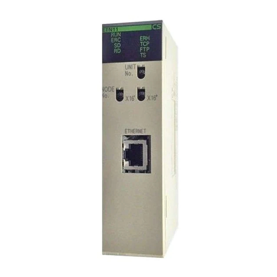
Ethernet Connector Used to connect the Ethernet transceiver cable. Power Supply Terminals Used to connect an external 24-VDC power supply for the transceiver. CS1W-ETN11 (10Base-T) Front Indicators Display the operating status of the Unit. Unit Number Switch Used to set the Ethernet Unit's unit number in one digit hexadecimal. - Page 51 Unit Components Section 3-3 CS1W-ETN01 and CS1W-ETN11 Back Local IP Address Switches Used to set the Ethernet Unit's IP address in eight digits hexadecimal. Each communications device connected to the Ethernet network is allocated a unique Ethernet address. For the Ethernet Unit, this Ethernet address is shown on the right side of the Unit as a 12-digit hexadecimal number.
- Page 52 Unit Components Section 3-3 CJ-series Ethernet Units CJ1W-ETN11 (10Base-T) Front Slider Mount to other Units. Indicators Display the operating status of the Unit. ETN11 ERC SD ERH TCP FTP Unit Number Switch Used to set the Ethernet Unit’s unit number in one UNIT digit hexadecimal.
-
Page 53: Indicators
Note The Ethernet address can also be checked using the FINS command, CON- TROLLER DATA READ. (Refer to 11-3-2 CONTROLLER DATA READ.) 3-3-2 Indicators The status of the indicators show the operating status of the Unit. CJ1W-ETN11 (10Base-T) CS1W-ETN01 (10Base-5) CS1W-ETN11 (10Base-T) ETN11 ERC SD ERH TCP FTP Indicator Color Status... -
Page 54: Switch Settings
Switch Settings Section 3-4 Indicator Color Status Meaning Yellow Not lit Not running internode test. (Internode Testing) Running internode test. Switch Settings This section explains how to set the various switches on the Ethernet Unit. 3-4-1 CS-series Ethernet Units Setting the Unit Number The unit number is used to identify individual CPU Bus Units when more than one CPU Bus Unit is mounted to the same PC. - Page 55 Switch Settings Section 3-4 DM Area Allocations Unit No. Allocated words Unit No. Allocated words (decimal) (decimal) 0 (0) D30000 to D30099 8 (8) D30800 to D30899 1 (1) D30100 to D30199 9 (9) D30900 to D30999 2 (2) D30200 to D30299 A (10) D31000 to D31099 3 (3)
-
Page 56: Cj-Series Ethernet Units
Switch Settings Section 3-4 Setting range: 0 to F Local IP Address Switch No. 1 2 . 3 4 . 5 6 . 7 8 . The switches are all factory-set to 0 (00.00.00.00). The Ethernet Unit cannot be used with this setting; a proper IP address must be set. The following set- tings cannot be made for the IP address, or the ERC indicator will flash. - Page 57 Switch Settings Section 3-4 Unit Number and CPU Bus With CJ-series PCs, words are automatically allocated in the CIO Area and Unit Allocations the DM Area. The Ethernet Unit uses these words for receiving control data from the CPU Unit and for notifying the CPU Unit of Ethernet Unit and com- munications status.
-
Page 58: Mounting To A Pc
Mounting to a PC Section 3-5 When using the automatic generation method for address conversion, set the node number to the same value as the rightmost byte of the local IP address. If this is not possible, then either the IP address table method or the combined method must be used for address conversion. -
Page 59: Mounting To A Cj-Series Pc
Mounting to a PC Section 3-5 3-5-2 Mounting to a CJ-series PC Ethernet Units can be connected to either a CJ-series CPU Rack or a CJ- series Expansion CPU Rack. Connect the Ethernet Unit in any of the posi- tions shown below using the sliders on the top and bottom of the Unit. Up to four Ethernet Units can be mounted to a single PC. -
Page 60: Connecting To The Network
Output Signal ground Not used Connector Frame ground hood CS1W-ETN11 and CJ1W- The following standards and specifications apply to the connectors for the Ethernet twisted-pair cable. ETN11 • Electrical specifications: Conforming to IEEE802.3 standards. • Connector structure: RJ45 8-pin Modular Connector... -
Page 61: Connecting The Cable
Connecting to the Network Section 3-6 Connector Signal name Abbr. Signal direction Transmission data + Output Transmission data – TD– Output Reception data + Input Not used. Not used. Reception data – RD– Input Not used. Not used. 3-6-3 Connecting the Cable Transceiver Cable (for CS1W-ETN01) !Caution Turn OFF the PC’s power supply before connecting or disconnecting trans- ceiver cable. - Page 62 Lock post Slide latch Lock post CS1W-ETN01 Twisted-pair Cable (for CS1W-ETN11 and CJ1W-ETN11) !Caution Turn OFF the PC’s power supply before connecting or disconnecting twisted- pair cable. !Caution Allow enough space for the bending radius of the twisted-pair cable as shown in below.
-
Page 63: Connecting The Power Supply (Cs1W-Etn01 Only)
Examples of the above two steps are provided in Appendix A. Request ca- ble installation from a qualified professional. 3. Connect the cable to the connector on the Ethernet Unit. Be sure to press in the cable until it locks into place. Example: CS1W-ETN11 RJ45 Modular Connector CS1W-ETN11 3-6-4 Connecting the Power Supply (CS1W-ETN01 Only) Connect a 24-VDC power supply to the power supply terminals. - Page 64 Connecting to the Network Section 3-6 Maker Model Specifications Applicable power line range (stranded wire) J.S.T.MFG.CO., V1.25-N3A Fork terminal with 0.25 to 1.65 mm vinyl insulation (AWG: #22 to #16) V1.25-MS3 Ring terminal with vinyl insulation MOLEX JAPAN VSY1.25-3.5L Fork terminal with 0.3 to 1.65 mm CO.,LTD vinyl insulation...
- Page 65 20.4 VDC to 26.4 VDC (24 VDC –15% + 10 %) fluctuation Current consumption 300 mA max. at 24 VDC (per node) Inrush current 2.5 A max. (24 VDC when rise time is 5 ms) OMRON’s S82J Series is recommended for the power supply.
-
Page 66: Creating An I/O Table
Creating an I/O Table Section 3-7 Note 1. Use a power supply that meets these specifications. 2. If the power supply is separate from a node, make sure that these specifi- cations are met at the node’s terminal block. 3. Turn ON the Unit’s power supply either before or at the same time as the CPU Unit’s power supply. -
Page 67: Creating Routing Tables
Creating Routing Tables Section 3-8 explanation of how to create an I/O table using a CX-Programmer, refer to the CX-Programmer User’s Manual. Use the following procedure to create the I/O table. Note With the CJ Series, it is necessary to create an I/O table only when I/O alloca- tion is performed by the user. - Page 68 Creating Routing Tables Section 3-8 Local Network Table The local network table is a table describing the correspondences among unit numbers of the Communications Units and Boards mounted to each node (PC or FA Computer). Unit #04 Example Unit #05 Local Network Table Unit #06 Unit #07...
-
Page 69: Connecting And Using A Peripheral Device For The Pc
Creating Routing Tables Section 3-8 3-8-2 Connecting and Using a Peripheral Device for the PC Routing tables must be created by a CX-Net connected to the PC. (They can- not be created using a Programming Console.) For details on how to connect and use a CX-Net, refer to the CX-Programmer User’s Manual. - Page 70 Creating Routing Tables Section 3-8 Example 2: Three Interconnected Networks This example shows the relay network table settings for three different inter- connected networks. Relay Network Table Relay Node network network PC #1 Node #a Network #A PC #2 Node #b Node #c PC #3 Network #B...
- Page 71 Creating Routing Tables Section 3-8 Example 3: All Nodes This example uses the following configuration to show the routing tables for all nodes. Unit #5 Node #6 Network #10 Unit #4 Unit #3 Node #5 Node #4 Unit #7 Unit #2 Node #15 Node #3 Network #30...
-
Page 72: System Setup
System Setup Section 3-9 System Setup The settings for the Ethernet Unit’s basic and special functions are made in the CPU Bus Unit System Setup. These settings, and the situations in which the settings must be made, are shown in the following table. For details on how to make the settings, refer to 4-2 CPU Bus Unit System Setup. -
Page 73: Creating An Ip Address Table
Creating an IP Address Table Section 3-10 Item Default Destination mail address Not set. SMTP server address 0.0.0.0 (Not set.) For information on IP address table settings, refer to 3-10 Creating an IP Address Table. For information on IP router table settings, refer to 3-11 Creat- ing an IP Router Table. -
Page 74: Checking Communications
Checking settings such as an Ethernet node. FINS addresses for using the FINS communications service. Test objects Ethernet Units and Ether- OMRON Units and Boards net devices that support that support FINS commu- PING. nications service intern- ode testing. Network classification... -
Page 75: Simple Startup Test Example
Checking Communications Section 3-12 Note 1. The internode test can be easily carried out by manipulating dedicated control switches for the Ethernet Unit. For details, refer to 9-3 Internode Test. 2. Internode testing of the FINS communications service can also be carried out by means of the FINS commands INTERNODE ECHO TEST and BROADCAST TEST RESULTS READ. - Page 76 Checking Communications Section 3-12 Local network table Local network Unit number address Set to the same value as the unit number set with the rotary switch on the front of the Unit. When the above settings have been completed, reset the power supply. 4.
- Page 77 Checking Communications Section 3-12 Normal Response RSV GCT DNA DA1 DA2 SNA SA1 SA2 SID Command code (READ) Data read Data read from D100 from D249 Completion code (Normal completion)
-
Page 78: System Setup And Memory Allocations
SECTION 4 System Setup and Memory Allocations This section explains the System Setup and the words allocated in the CIO Area and the DM Area for Ethernet Units. Allocated Words ..........CPU Bus Unit System Setup. -
Page 79: Allocated Words
Allocated Words Section 4-1 Allocated Words The Ethernet Unit is allocated words in the following three areas for reading settings and status. • System Setup for CPU Bus Units Stores initial setup for the Ethernet node. • Allocated Words in the CIO Area Stores software switches and status information for functions. -
Page 80: Cpu Bus Unit System Setup
CPU Bus Unit System Setup Section 4-2 CIO Area Allocations Unit No. Allocated words Unit No. Allocated words (decimal) (decimal) 0 (0) CIO 1500 to CIO 1524 8 (8) CIO 1700 to CIO 1724 1 (1) CIO 1525 to CIO 1549 9 (9) CIO 1725 to CIO 1749 2 (2) -
Page 81: Settings
CPU Bus Unit System Setup Section 4-2 mer. With CJ-series Ethernet Units, however, it is possible to set the local IP address and the subnet mask using the FINS command IP ADDRESS WRITE. For details, refer to 11-3-20 IP ADDRESS WRITE . 4-2-1 Settings Item... - Page 82 CPU Bus Unit System Setup Section 4-2 Note When using automatic address generation (the default) for address conver- sion, make the following settings. With the CS Series, set local IP address DIP switches 7 and 8 on the back of the Ethernet Unit to the same value as the node number setting on the front of the Unit, and set all other host settings to 0.
- Page 83 CPU Bus Unit System Setup Section 4-2 Set the local IP address in the allocated words in the DM Area when using the CPU Bus Unit System Setup at its default settings (i.e., for simple operation). The setting is usually made with a Programming Console. Application Setting device Setting area...
- Page 84 CPU Bus Unit System Setup Section 4-2 If the login name is incorrectly specified, or if no login name is specified at all, the default login name of “CONFIDENTIAL” will be used and no FTP pass- word will be required. The default is for no FTP login name to be set. FTP Password Enter the Unit’s FTP server password using up to eight characters.
-
Page 85: Mail Settings
CPU Bus Unit System Setup Section 4-2 IP network number IP address of IP router 130.26.0.0 130.25.36.253 Setting range: 0.0.0.0 to 255.255.255.255 Setting range: 0.0.0.0 to 255.255.255.0 A maximum of eight records can be registered. The default is for nothing to be set. - Page 86 CPU Bus Unit System Setup Section 4-2 • User Data (Refer to Sending User Data for Errors below.) • Error Log Information (Refer to Sending Error Log Information for Errors below.) • Status Information (Refer to Status Information for Errors below.) If none of these types of data is selected, mail will not be sent even if the set- ting is made for mail to be sent whenever an error is registered.
- Page 87 CPU Bus Unit System Setup Section 4-2 If none of these types of data is selected, mail will not be sent even if the set- ting is made for mail to be sent whenever an error is registered. Setting Meaning Not selected (Default) Mail is not sent periodically.
-
Page 88: Cio Area Allocations
CIO Area Allocations Section 4-3 CIO Area Allocations The various kinds of data are stored in the offset positions shown in the fol- lowing diagram, from the beginning word in the area for each Unit. The beginning word n is calculated by the following equation: Beginning word n = CIO 1500 + (25 x unit number) Offset Related communications services... - Page 89 CIO Area Allocations Section 4-3 Unit Control Switches (CPU Unit to Ethernet Unit) 15 14 13 12 11 10 Internode Test Start Switch Socket Force-close Switch Mail Send Switch Switch Status Manipulated Unit operation Reference (Not used.) Internode Test Start Switch User Executes internode test while ON.
- Page 90 CIO Area Allocations Section 4-3 Status of UDP/TCP Sockets 1 to 8 (Ethernet Unit to CPU Unit) 15 14 13 12 11 10 n+1 to n+16 Opening Flag Receiving Flag Results Storage Error Flag Sending Flag TCP/UDP Open Flag Closing Flag Flag Status Manipulated...
- Page 91 Page 173 Unit FTP server on standby. (FTP client not connect. 2 to 14 (Not used.) Power status Unit Power is being supplied CS1W-ETN11: Always Page 42 (CS1W-ETN01 only) to transceiver. CJ1W-ETN11: Always Unit Power is not being supplied to transceiver.
- Page 92 CIO Area Allocations Section 4-3 Power Status (Bit 15) Turns ON while power is being supplied from the Ethernet Unit to the trans- ceiver, and OFF when power is not being supplied. Check to be sure that this bit is ON before beginning communications. Error Status (Ethernet Unit The status of errors that occur at the Ethernet Unit is reflected as shown in the to CPU Unit)
- Page 93 CIO Area Allocations Section 4-3 Note A transceiver is built into the CS1W-ETN11 and CJ1W-ETN11. If this bit turns ON, the Ethernet Unit has malfunctioned. Socket Service Request When a socket service request is executed by control switch manipulation, it Switches 1 to 8 (CPU Unit is the following bits that are manipulated.
-
Page 94: Dm Area Allocations
DM Area Allocations Section 4-4 DM Area Allocations The various kinds of data are stored in the offset positions shown in the fol- lowing diagram, from the beginning word in the area for each Unit. The beginning word m is calculated by the following equation: Beginning word m = D30000 + (100 x unit number) Offset Related communications services... - Page 95 DM Area Allocations Section 4-4 Specify, in hexadecimal, the number of bytes of test data to be sent between nodes. 0000 (Hex): 1,996 bytes 0001 to 07CC (Hex): 1 to 1,996 bytes Internode Test Response Monitoring Time (CPU Unit to Ethernet Unit) 15 14 13 12 11 10 9 Response monitoring time (0000 to FFFF Hex) Specify, in hexadecimal, the amount of time to wait for the internode test...
- Page 96 DM Area Allocations Section 4-4 When the count reaches FFFF (Hex), it will start over again at 0. The count value will be retained until the internode test is restarted. Note When a routing table error or a transmission parameter error occurs, the num- ber of internode tests is not incremented.
- Page 97 DM Area Allocations Section 4-4 Mail Status (Ethernet Unit to CPU Unit) 15 14 13 12 11 10 m+17 User mail status Periodic mail status Error log mail status The transmission statuses of user mail, periodic mail, and error log mail are stored in this word as shown in the following table.
- Page 98 DM Area Allocations Section 4-4 be stored here and the ERC indicator will flash. (Refer to Setting the Local IP Address.) CJ-series Ethernet Units 15 14 13 12 11 10 9 m+98 m+99 IP address: 12.34.56.78 (Hex) If the local IP address in the CPU Bus Unit System Setup is set to a value other than 00.00.00.00, this area (words m+98 and m+99) will act as an IP Address Display Area and the local IP address set in the CPU Bus Unit Sys- tem Setup will be read and stored here when the power is turned ON or the...
-
Page 100: Fins Communications
SECTION 5 FINS Communications This section provides information on communicating on Ethernet Systems and interconnected networks using FINS commands. The information provided in the section deals only with FINS communications in reference to Ethernet Units. FINS commands issued from a PC are sent via the SEND(090), RECV(098), and CMND(490) instructions programmed into the user ladder-diagram program. -
Page 101: Overview Of Fins Communications
The FINS communications service is a function for controlling operations such as sending and receiving data, changing modes, and so on, between nodes on OMRON factory automation networks. It provides the following features. • Communications instructions are executed in the user program. - Page 102 • Units and Boards that support FINS commands return responses auto- matically, so there is no need for a program at the receiving end. • The FINS communications service is mainly used between OMRON CPU Bus Units, CPU Units, and Support Boards for FA Computers. By cor- rectly setting information such as headers, however, it can also be used from ordinary Ethernet communications devices.
-
Page 103: Procedure Before Using Fins Communications
Procedure Before Using FINS Communications Section 5-2 Procedure Before Using FINS Communications Start Determine the address conversion method for the destination IP address. IP Address Table Automatic Generation Combined Method Converted from table of corre- Automatically converted from IP address table is referenced; spondences between FINS node FINS node number. -
Page 104: Sending Commands From A Pc
Sending Commands From a PC Section 5-3 Sending Commands From a PC FINS commands can be sent from the user’s ladder-diagram program in the PC by using the SEND(090), RECV(098), and CMND(490) instructions. SEND(090): Writes I/O data from the local node to another node. RECV(098): Reads I/O data from another node to the local node. - Page 105 Sending Commands From a PC Section 5-3 Using SEND(090), RECV(098), and CMND(490) Make the settings shown below when using the SEND(090), RECV(098), and CMND(490) instructions in the user’s ladder-diagram program in the PC. SEND(090) The SEND(090) instruction sends the data in n number of words, starting from the beginning word S at the local node, to the words starting from the begin- ning word D at the remote destination node (node number N).
- Page 106 Sending Commands From a PC Section 5-3 RECV(098) With the RECV(098) instruction, the data in m number of words, starting from the beginning word S at the remote node (node number M) is received at the words starting from the beginning word D at the local node. Local node Remote node number N Number...
- Page 107 Sending Commands From a PC Section 5-3 CMND(049) The CMND(049) instruction sends n bytes of command data, starting from the beginning word S at the local node, to the node at node number N. the data in m number of words, starting from the beginning word S at the remote node (node number M) is received at the words starting from the beginning word D at the local node.
- Page 108 Sending Commands From a PC Section 5-3 Commands Addressed to CS/CJ-series CPU Units The following table provides a list of FINS commands that can be processed by a CS/CJ-series CPU Unit. For details, refer to the CS/CJ-series Program- mable Controllers Communications Commands Reference Manual (W342). For details on FINS commands that can be processed by the Ethernet Unit, refer to Section 11 FINS Commands Addressed to Ethernet Units.
- Page 109 Sending Commands From a PC Section 5-3 Usage Command Name Function code File memory FILE NAME READ Reads file memory data. SINGLE FILE READ Reads a specified length of file data from a specified position within a single file. SINGLE FILE WRITE Writes a specified length of file data from a specified position within a single file.
- Page 110 Sending Commands From a PC Section 5-3 Writing Programs Programs incorporating the SEND(090), RECV(098), and CMND(490) instructions are generally created using the Communications Port Enabled Flag and the Communications Port Error Flag as input conditions. CS/CJ- series CPU Units have eight communications ports. Only one instruction can be executed at any given port at one time, however, so the program must not overlap the use of any of the ports.
- Page 111 Sending Commands From a PC Section 5-3 Communications Flags The execution status of the SEND(090), RECV(098), and CMND(490) instruc- tions is always reflected by the communications flags (i.e., the Communica- tions Port Enabled Flag and the Communications Port Error Flag). The CS/ CJ-series CPU Unit’s communications flags are allocated in the Auxiliary Area as shown in the following table.
- Page 112 Sending Commands From a PC Section 5-3 Communications Port Error Flag and Completion Codes CMND(490) Errors that occur when CMND(490) is used generate a Communications Port Error Flag and are recorded in a communications port completion code only in the following cases: •...
-
Page 113: Program Example
Sending Commands From a PC Section 5-3 5-3-2 Program Example Execution condition (See note.) 000000 A20207 120002 When the Communications Port Enabled Flag for port 7 KEEP is ON, and RECV(098) is not being executed, the send 120000 execution program will start when execution condition CIO 000000 turns ON. -
Page 114: Transmission Delays
Sending Commands From a PC Section 5-3 (Continued from previous page.) Execution condition (See note.) When the Communications Port Enabled Flag for port 7 000001 A20207 120000 is ON, and SEND(090) is not being executed, the trans- KEEP mission execution program will start when execution 120002 condition CIO 000001 turns ON. - Page 115 Sending Commands From a PC Section 5-3 SEND(090) The transmission delay for the SEND(090) instruction can be calculated using the following equation, which is illustrated in the following diagram. Max. delay = Local node service cycle + local node service processing time + transmission processing time + reception processing time + remote node service cycle + remote node service processing time + CPU data set processing time (remote node)
- Page 116 Sending Commands From a PC Section 5-3 Item Calculation CPU Bus Unit service cycle (local node) PC cycle time = 10 ms CPU Bus Unit service processing time (local 1 ms node) 256 x 0.011 + 3 = 5.816 ≅ 6 ms Transmission processing time 256 x 0.011 + 3 = 5.816 ≅...
-
Page 117: Sending Commands From A Host Computer
Sending Commands From a Host Computer Section 5-4 Example Calculations The following example shows calculations for receiving 256 words between two PC nodes using RECV(098). The local node’s CPU cycle time is 10 ms, and the remote node’s CPU cycle time is 15 ms. Calculations are shown in the following table. -
Page 118: Fins Frames
Sending Commands From a Host Computer Section 5-4 Example 1: Intranetwork In this example, the host computer and the remote node (Ethernet Unit) are Addressing on the same network. The communications parameters specified from the host computer would be as follows: Destination IP Address: 196.36.32.100 (Ethernet Unit of remote node) UDP port number: FINS UDP port No. - Page 119 Sending Commands From a Host Computer Section 5-4 FINS Command Frame Configuration Size (bytes) Contents Displays frame information Reserved by system. Permissible number of gateways Destination network address Destination node address FINS header Destination unit address Source network address Source node address Source unit address Service ID Main request code...
-
Page 120: Sample Program
Sending Commands From a Host Computer Section 5-4 dress used for Ethernet. 00 (Hex): Local PC Unit 01 to 7E (Hex): Destination node number (1 to 126) FF (Hex): Broadcasting When multiple Communications Units are mounted, DA1 specifies the node number of the Unit connected to the network specified by DNA. DA2 (Destination Unit Address) Specifies the number of the Unit at the destination node. - Page 121 Sending Commands From a Host Computer Section 5-4 FINS COMMUNICATIONS SAMPLE PROGRAM main(argc,argv) argc; char *argv[]; sockfd; struct sockaddr_in ws_addr,cs_addr; char fins_cmnd[MAX_MSG],fins_resp[MAX_MSG]; sendlen,recvlen,addrlen; char sid=0; extern recv_fail(); GENERATE UDP SOCKET if((sockfd=socket(AF_INET,SOCK_DGRAM,0))<<0) err_exit(”can’t open datagram socket”); ALLOCATE IP ADDRESS AND PORT # TO SOCKET bzero((char*)&ws_addr,sizeof(ws_addr));...
-
Page 122: Delays For Accessing Pc Memory
Sending Commands From a Host Computer Section 5-4 else{ err_exit(”send error”); RECEIVE FINS RESPONSE addrlen = sizeof(cs_addr); if((recvlen = recvfrom(sockfd,fins_resp,MAX_MSG,0,&cs_addr,&addrlen)) <0){ if(errno == EINTR) RE-SEND FINS COMMAND goto CMND_SEND; /* err_exit(”receive error”); else{ STOP RESPONSE MONITOR TIMER alarm(0); /* printf(”recv length %d¥n”,recvlen); if(recvlen<14) /* ILLEGAL RESPONSE LENGTH CHECK err_exit(”FINS length error”);... -
Page 123: Fins Server
FINS Server Section 5-5 words read) + CPU cycle time + CPU data read processing time (Refer to page 96) Note 1. The transfer time may exceed the calculated value due to the actual oper- ating environment. Factors affecting the transfer time are network traffic, the window size of each node, Ethernet Unit traffic (e.g., socket services, FTP server communications, etc.), and the system configuration. -
Page 124: Socket Services
SECTION 6 Socket Services This section describes the functionality provided by the Ethernet Unit via the socket services. Overview ........... . . 6-1-1 Socket Service Functions . -
Page 125: Overview
Overview Section 6-1 Overview 6-1-1 Socket Service Functions The socket services allow devices on the Ethernet to send and receive vari- ous data using the UDP or TCP protocol. The socket services can be used by CS/CJ-series PCs through the user program by manipulating dedicated bits (called Socket Service Request Switches) or by executing the CMND(490) instruction. -
Page 126: Sockets
Overview Section 6-1 Specific Socket Service Functions The socket service functions listed in the following table can be executed either using Socket Service Request Switches or using CMND(490). Protocol Socket service request Open UDP socket Receive via UDP socket Send via UDP socket Close UDP socket Open TCP socket, passive Open TCP socket, active... -
Page 127: Differences Between Tcp And Udp
Overview Section 6-1 quently, port numbers 1024 and above should be used for socket services. The Ethernet Unit does not support port #0. Some port numbers over 1024 may be reserved on some workstations (for example, the X-window server is port #6000). Do not use port numbers that are already reserved for other processes. -
Page 128: Opening Tcp Sockets
Overview Section 6-1 6-1-6 Opening TCP Sockets To achieve highly reliable data communications, TCP establishes a virtual communications circuit between the two nodes before starting data transmis- sions. The virtual communications circuit is known as a “connection.” Passive OPEN and Active An open command is executed for a node to establish a connection. -
Page 129: Fragmentation Of Send Data
Overview Section 6-1 Host computer Ethernet Unit (server) (client) Passive open Active open Connection requested Connection established Connection established Data send request Send data ACK (acknowledge) Data receive request Send next data Data send request Send data Data receive request ACK (acknowledge) Next data receive request Close... - Page 130 Overview Section 6-1 Sending User Program Ethernet Unit Receiving Node Receiving Computer 4. First receive request 1. Send request 1,984bytes 1,984 bytes 1,024 bytes Source data Data A Data A Data A Only first Data B 1,024 bytes 960 bytes 5.
-
Page 131: Maximum Transmission Delays
Overview Section 6-1 data request is set smaller than the actual length of the data, all received data exceeding the set data length will be discarded. 6-1-8 Maximum Transmission Delays The transmission delays for socket service is calculated as the sum of the communications processing times for both nodes. -
Page 132: Precautions In Using Socket Services
Overview Section 6-1 Item Formula Remote send processing time 10 x 5 + 20 x 2 + 30 = 120 ms Remote receive processing time 10 x 5 + 20 x 2 + 30 = 120 ms Maximum transmission delay 95 + 95 + 120 + 120 = 430 ms 6-1-9 Precautions in Using Socket Services... -
Page 133: Using Socket Services With Socket Service Request Switches
Using Socket Services with Socket Service Request Switches Section 6-2 • Data can remain in a buffer at the local node if the remote TCP socket closes during communications. Any data remaining in the buffer will be discarded when the TCP socket is closed. To avoid problems of this nature, steps will have to be taken in the application program, such as sending data to enable closing, and then only closing once reception of this data has been confirmed. - Page 134 Using Socket Services with Socket Service Request Switches Section 6-2 An illustration of using Socket Service Request Switches to execute socket services is provided below. CS/CJ-series PC Host computer or other device CPU Unit Ethernet Unit TCP data User program transfers System call...
-
Page 135: Socket Service Parameters
Using Socket Services with Socket Service Request Switches Section 6-2 6-2-1 Socket Service Parameters The Socket Service Parameter Areas in which parameters are set to request socket services is in the CPU Bus Unit Area in the DM Area of the CPU Unit. The Socket Service Parameter Areas are allocated as shown in the following diagrams. - Page 136 Using Socket Services with Socket Service Request Switches Section 6-2 Parameter Settings The following table shows the parameters that are required for each service and the use of the parameters by the socket service. UDP Socket Services Parameter No. of Range Socket service words...
- Page 137 Using Socket Services with Socket Service Request Switches Section 6-2 Local UDP/TCP Port No. Specify the number of the UDP or TCP port for the socket to use for communi- cations. • Do not specify the port being used as the FINS UDP port (default: 9600) in an open request for a UDP socket.
-
Page 138: Response Codes
Using Socket Services with Socket Service Request Switches Section 6-2 Remote UDP/TCP Port No. Specify the UDP or TCP port number used by the remote device. • This parameter is not used when making a receive request for a UDP socket. - Page 139 Using Socket Services with Socket Service Request Switches Section 6-2 lowing response codes will be stored depending on the service that was requested. UDP Socket Open Request Response Meaning code 0000 Normal end 0105 Local IP address setting error. 0302 CPU Unit error;...
- Page 140 Using Socket Services with Socket Service Request Switches Section 6-2 Response Meaning code 110C Request Switch turned ON during other processing. 220F Specified socket is already processing a send request. 2210 The specified socket is not open. 2211 Unit is busy; cannot execute. 2607 Specified Socket Service Parameter Area is already being used for another socket.
- Page 141 Using Socket Services with Socket Service Request Switches Section 6-2 Response Meaning code 004B Error in communications with remote node (ECONNRESET). (See note.) 004E Remote IP address parameter error (ENETUNREACH). (See note.) 0051 Remote IP address parameter error (EHOSTUNREACH). (See note.) 0053 Error in communications with remote node (ETIMEDOUT) or remote node does not exist.
- Page 142 Using Socket Services with Socket Service Request Switches Section 6-2 Response Meaning code 0053 Communications error with remote node (ETIMEDOUT). No remote node. 0081 The specified socket was closed during open processing. Note These response codes will be returned only on large, multilevel networks. TCP Socket Receive Request Response Meaning...
-
Page 143: Socket Service Request Switches
Using Socket Services with Socket Service Request Switches Section 6-2 Response Meaning code 110C Request Switch turned ON during other processing. 220F Specified socket is already processing a send request. 2210 The specified socket is not open. 2211 Unit is busy; cannot execute. 2607 Specified Socket Service Parameter Area is already being used for another socket. - Page 144 Using Socket Services with Socket Service Request Switches Section 6-2 Offset n+19 Socket Service Socket Service Request Switches 2 Request Switches 1 Socket Service Socket Service n+20 Request Switches 4 Request Switches 3 Socket Service Socket Service n+21 Request Switches 6 Request Switches 5 Socket Service Socket Service...
- Page 145 Using Socket Services with Socket Service Request Switches Section 6-2 The configuration of each set of Socket Service Request Switches is shown in the following diagram. 15 14 13 12 11 10 UDP Open Request Switch TCP Passive Open Request Switch TCP Active Open Request Switch Send Request Switch Receive Request Switch...
-
Page 146: Udp/Tcp Socket Status
Using Socket Services with Socket Service Request Switches Section 6-2 6-2-4 UDP/TCP Socket Status The status of the UDP and TCP sockets is provided in the Socket Status Words shown in the following diagram. There is a status word for each socket for both UDP and TCP. -
Page 147: Application Procedure
Using Socket Services with Socket Service Request Switches Section 6-2 Note The TCP socket connection status is also provided as codes in the following words of the words allocated to the Ethernet Unit in the CPU Bus Unit Area in the DM Area: D30000 + (100 x unit number) +9 to +16. -
Page 148: Socket Services And Socket Status
Using Socket Services with Socket Service Request Switches Section 6-2 Precautions A Socket Service Parameter Area cannot be used for other sockets once open processing has been successfully completed for it. Check the socket status before attempting to open a socket. TCP socket status is provided in words m+9 to m+16 in the DM Area for sockets 1 to 8. -
Page 149: Timing Charts
Using Socket Services with Socket Service Request Switches Section 6-2 The flow is similar for other socket services. Replace the names of the appro- priate flags in the flowchart to adapt it to other socket services. Start UDP Open Program Flow Error Evaluation Check Socket Open Flag. - Page 150 Using Socket Services with Socket Service Request Switches Section 6-2 turning OFF the Request Switch for the canceled process and turning of the Close Request Switch, allowing time for the response code to be read. At least one PC cycle time be tween response codes Open, Send, or Receive Request Switch...
-
Page 151: Tcp/Ip Communications Programming Example
Using Socket Services with Socket Service Request Switches Section 6-2 6-2-8 TCP/IP Communications Programming Example The following programming example illustrates transferring 100 bytes of data between an Ethernet Unit and a host computer using TCP/IP communica- tions. System Configuration The programming example uses the following system configuration. For the TCP connection, the Ethernet Unit uses a passive open and the host com- puter uses an active open. - Page 152 Using Socket Services with Socket Service Request Switches Section 6-2 Program Memory Map The send and receive data and bits (flags) used by the program are shown in the following diagram. DM Area Send data, 100 bytes (100 = 0064 Hex) Receive data, 100 bytes (100 = 0064 Hex) CIO Area The following bits and flags are used to control CMND(490) execution.
- Page 153 Using Socket Services with Socket Service Request Switches Section 6-2 Programming Example 000000 TCP Passive Open @RSET When the TCP Open Bit (CIO 000000) turns ON, the TCP 000100 Open Error Flag (CIO 000100) is turned OFF and the TCP Opening Flag (CIO 000200) is turned ON to initialize pro- cessing.
- Page 154 Using Socket Services with Socket Service Request Switches Section 6-2 Continued from previous page. 000001 000201 151905 TCP Send <>(305) When the TCP Send Bit (CIO 000002) turns ON, the TCP 000101 Send Error Flag (CIO 000102) is turned OFF and the TCP D30027 Sending Flag (CIO 000202) is turned ON to initialize pro- #0000...
-
Page 155: Udp/Ip Communications Programming Example
Using Socket Services with Socket Service Request Switches Section 6-2 Continued from previous page. 000003 000203 When the TCP Receiving Flag (CIO 000203) turns ON, MOV(21) the following parameters are written to the parameter #0001 area for socket number 1. D30018: 0001 Hex = UDP/TCP socket No. - Page 156 Using Socket Services with Socket Service Request Switches Section 6-2 Basic Operations • CIO 000000 is turned ON to request opening a UDP socket from the Ethernet Unit. • CIO 000001 is turned ON to request closing the UDP socket from the Ethernet Unit.
- Page 157 Using Socket Services with Socket Service Request Switches Section 6-2 Programming Example 000000 UDP Open @RSET When the UDP Open Bit (CIO 000000) turns ON, the UDP 000100 Open Error Flag (CIO 000100) is turned OFF and the UDP Opening Flag (CIO 000200) is turned ON to initialize pro- @SET cessing.
- Page 158 Using Socket Services with Socket Service Request Switches Section 6-2 Continued from previous page. 000002 000202 MOV(21) When the UDP Sending Flag (CIO 000202) turns ON, the #0001 following parameters are written to the parameter area for socket number 1. D30018 D30018: 0001 Hex = UDP/TCP socket No.
- Page 159 Using Socket Services with Socket Service Request Switches Section 6-2 Continued from previous page. 000003 000203 When the UDP Receiving Flag (CIO 000203) turns ON, MOV(21) the following parameters are written to the parameter area #0001 for socket number 1. D30018: 0001 Hex = UDP/TCP socket No.
-
Page 160: Using Socket Services With Cmnd(490)
Using Socket Services with CMND(490) Section 6-3 Using Socket Services with CMND(490) Service request commands can be sent to the Ethernet Unit by executing the CMND(490) instruction in the ladder diagram. CS/CJ Ethernet Units support the same functionality as the CV-series Ethernet Unit, so heritage programs can be easily corrected and reused. -
Page 161: Udp/Tcp Socket Status
Using Socket Services with CMND(490) Section 6-3 Note If there is more than one Communications Unit mounted to the PC, the FINS network address must be set as a parameter for CMND(490) and a local net- work table must be created in the routing tables from the CX-Programmer. 6-3-1 UDP/TCP Socket Status The status of the UDP and TCP sockets is provided in the Socket Status... - Page 162 Using Socket Services with CMND(490) Section 6-3 Flag Status Manipulated Unit operation Results Storage Error Unit Turns ON when there is an error in the Results Storage Area speci- Flag fied for the service request command to the Ethernet Unit. This flag will turn ON at the same timing as turning OFF bits 0 to 3 (i.e., at completion of processing).
- Page 163 Using Socket Services with CMND(490) Section 6-3 1,2,3... 1. Execute a socket service request command (MRC: 27) for the Ethernet Unit using CMND(490). Ethernet Unit User program Socket service CMND Request command 2. CMND(490) ends normally when the socket service request command is received and a response is returned (response code: 0000).
-
Page 164: Socket Services And Socket Status
Using Socket Services with CMND(490) Section 6-3 6-3-2 Socket Services and Socket Status When using socket services, it is important to consider the timing of the status changes in the socket status area. The diagram below shows a program flow- chart for opening UDP. -
Page 165: Communications Timing Chart
Using Socket Services with CMND(490) Section 6-3 6-3-3 Communications Timing Chart The timing of the status changes of the bits in the socket status area and the Port Enabled Flag is shown in the following diagram. Port Enabled Flag Opening Flag Receiving Flag Sending Flag Closing Flag... - Page 166 Using Socket Services with CMND(490) Section 6-3 SEND REQUEST Port Enabled Flag Running Running Error response code Normal response code CMND(490) response code Send Flag Opening Flag Results storage area Store normal response code SEND REQUEST Error SEND REQUEST Send complete command received command received (normal end)
-
Page 167: Tcp/Ip Communications Programming Example
Using Socket Services with CMND(490) Section 6-3 shown in the diagram also applies if a CLOSE REQUEST command is exe- cuted during OPEN REQUEST command execution, with the exception of the status of the Opening Flag. 6-3-5 TCP/IP Communications Programming Example The following programming example illustrates transferring 100 bytes of data between an Ethernet Unit and a host computer using TCP/IP communica- tions. - Page 168 Using Socket Services with CMND(490) Section 6-3 • One of the bits between CIO 000100 and CIO 000103 will turn ON if an error occurs. Refer to 6-2-2 Response Codes for information on errors. The following areas can be used to access details about errors: CMND(490) response codes Response codes in results storage area Network Communications Error Flags (A21900 to A21907)
- Page 169 Using Socket Services with CMND(490) Section 6-3 CMND(490) control data for TCP SEND REQUEST D00020 006EH 0004H 0001H 0110H 0000H 0032H Number bytes to receive: 4 bytes Number of bytes to send: 110 (006E ) bytes Command format = 10 bytes + 100 bytes send data CMND(490) control data for TCP RECEIVE REQUEST D00030 000CH 0004H 0001H 0110H 0000H 0032H...
- Page 170 Using Socket Services with CMND(490) Section 6-3 TCP CLOSE REQUEST response D01040 sponse 2714H code TCP CLOSE REQUEST results storage area D01050 sponse code D02000 TCP SEND REQUEST command data Send data: 100 bytes (0064 2713H 0001H 820BH C200H 0064H No.
- Page 171 Using Socket Services with CMND(490) Section 6-3 CIO Area The following bits and flags are used to control CMND(490) execution. The bits in CIO 0000 are used to signal execution, the bits in CIO 0001 are used to signal errors, and the bits in CIO 0002 are used to control the program so that the instruction is executed only once.
- Page 172 Using Socket Services with CMND(490) Section 6-3 Programming Example 000000 @RSET TCP Passive Open When the TCP Open Bit (CIO 000000) turns ON, the TCP 000100 Open Error Flag (CIO 000100) is turned OFF and the TCP Opening Flag (CIO 000200) is turned ON to initialize pro- cessing.
- Page 173 Using Socket Services with CMND(490) Section 6-3 Continued from previous page. 000002 TCP Send @RSET When the TCP Send Bit (CIO 000002) turns ON, the 000102 TCP Send Error Flag (CIO 000102) is turned OFF and the TCP Sending Flag (CIO 000202) is turned ON to initialize processing.
-
Page 174: Udp/Ip Communications Programming Example
Using Socket Services with CMND(490) Section 6-3 Note When using the above programming example, change the bit and word addresses as necessary to avoid using the same areas used by other parts of the user program or the CPU Bus Unit. 6-3-6 UDP/IP Communications Programming Example The following programming example illustrates transferring 100 bytes of data... - Page 175 Using Socket Services with CMND(490) Section 6-3 Program Memory Maps The send and receive data and bits (flags) used by the program are shown in the following diagrams. DM Area D00000 CMND(490) control data for UDP OPEN REQUEST 000AH 0004H 0001H 0110H 0000H 0032H Response monitor time: 5 s FINS communications port: Port #0 Remote Ethernet Unit designation...
- Page 176 Using Socket Services with CMND(490) Section 6-3 UDP OPEN response D01010 sponse 2701H code Stores the response after command execution. UDP OPEN REQUEST results storage area D01020 sponse code UDP CLOSE REQUEST command data D1030 2704H 0001H 8204H 1A00H Results storage area: set to D01050 (041A UDP socket number closed: set to 1 (0001 Command code UDP CLOSE REQUEST response...
- Page 177 Using Socket Services with CMND(490) Section 6-3 UDP SEND REQUEST response D03000 sponse 2703H code UDP SEND REQUEST results storage area D03010 No. of sponse send code bytes D04000 UDP RECEIVE REQUEST command data 2702H 0001H 820FH B400H 0064H 0000H Timeout value: Not set No.
- Page 178 Using Socket Services with CMND(490) Section 6-3 Programming Example 000000 @RSET UDP Open When the UDP Open Bit (CIO 000000) turns ON, the 000100 UDP Open Error Flag (CIO 000100) is turned OFF and the UDP Opening Flag (CIO 000200) is turned ON to initialize processing.
- Page 179 Using Socket Services with CMND(490) Section 6-3 Continued from previous page. 000002 UDP Send @RSET When the UDP Send Bit (CIO 000002) turns ON, the UDP 000102 Send Error Flag (CIO 000102) is turned OFF and the UDP Sending Flag (CIO 000202) is turned ON to initialize processing.
- Page 180 Using Socket Services with CMND(490) Section 6-3 Note When using the above programming example, change the bit and word addresses as necessary to avoid using the same areas used by other parts of the user program or the CPU Bus Unit.
-
Page 182: Ftp Server
SECTION 7 FTP Server This section describes the functions provided by the FTP server. Overview ........... . . Setting Login Names and Passwords . -
Page 183: Overview
Overview Section 7-1 Overview The Ethernet Unit supports the server functions of FTP (file transfer protocol), a standard protocol in TCP/IP. A host computer functioning as an FTP client on the Ethernet can read or write individual files in a Memory Card mounted to the CPU Unit or in EM file memory. -
Page 184: Setting Login Names And Passwords
Setting Login Names and Passwords Section 7-2 Setting Login Names and Passwords The default FTP login name is “CONFIDENTIAL” and no password is required. Login is completed by typing only “CONFIDENTIAL”. A different login name and a password can be set as required using the CPU Bus Unit Setup. Setting Restrictions The following restrictions apply to login names and passwords. - Page 185 Using File Memory Section 7-3 Note The HMC-AP001 PC Card Adapter can be used to mount a Memory Card in a PC card slot on a computer. File Types The MS-DOS file format is used, allowing the files to be handled as normal files on a Windows-based computer.
- Page 186 Using File Memory Section 7-3 File Names Handled by The files described in the following table can be read or written by the CPU CPU Unit Unit. File type File name Extension Contents Description Data file ******** .IOM Specified ranges of I/ •...
- Page 187 Using File Memory Section 7-3 Data File Format The format of data files (files with .IOM extensions) is shown in the following diagram. Byte position from the beginning of the file Reserved (48 bytes) Data Set the reserved bytes to all zeros (00 Hex). Writing Data Files via FTP In this example, the put command (see page 171) is used to write the follow- ing data to a file called DMDATA.IOM on a Memory Card, and then the READ...
-
Page 188: Ftp Server Application Example
FTP Server Application Example Section 7-4 FTP Server Application Example The following procedure shows how to use the FTP server by connection with the default login name, CONFIDENTIAL. No password is required. Note The login name and a password must be set in the CPU Bus Setup for the Ethernet Unit in the CPU Unit to use any login name other than CONFIDEN- TIAL. -
Page 189: Using Ftp Commands
Using FTP Commands Section 7-5 FTP Status Flag 0: FTP Server free 1: FTP Server busy 2. The FTP server can handle only one command at a time. 3. Do not simultaneously write a file with the same name to the same file de- vice in a CPU Unit from more than one Ethernet Unit or ladder diagram program. -
Page 190: Using The Commands
Using FTP Commands Section 7-5 7-5-2 Using the Commands open Format open [IP_address or host_name_of_FTP_server] Function Connects the FTP server. Normally when the FTP client is booted, the FTP server IP address is specified to execute this command automatically. user Format user [user_name] Function... - Page 191 Using FTP Commands Section 7-5 An error will occur if a file or directory of the same name already exists in the working directory. rmdir Format rmdir DIRECTORY_NAME Function Deletes the directory of the specified name from the remote host (Memory Card or EM File Memory).
- Page 192 Using FTP Commands Section 7-5 Function Allows the use of a wildcard character (*) to transfer multiple remote files from the Memory Card or EM File Memory to the local host. Format put file_name [DESTINATION_FILE_NAME] Function Transfers the specified local file to the remote host (Memory Card or EM File Memory).
-
Page 193: Error Messages And Ftp Status
Using FTP Commands Section 7-5 7-5-3 Error Messages and FTP Status Error Messages The error messages returned by the Ethernet Unit are listed in the following table. Message Meaning PPP is a directory. The path name indicated at PPP is a directory. PPP is not a directory. - Page 194 Using FTP Commands Section 7-5 PPP: Path name XXX: IP address Port number MM: FINS error code NN: Socket error code Checking FTP Status Note 1. File operations for files on the Memory Card are performed during FTP communications. Do not remove the Memory Card or turn OFF power to the PC while FTP is being used.
-
Page 195: Unix Application Example
UNIX Application Example Section 7-6 2. If the peripheral servicing time setting in the PC Setup is increased, FTP files will be transferred faster. UNIX Application Example The following procedure provides an example of FTP operations from a UNIX workstation. In this example, the following assumptions are made. •... - Page 196 UNIX Application Example Section 7-6 4. Change to the MEMCARD directory. Change to MEMCARD directory. 5. Change data type to binary. Binary data type set. 6. Transfer the file RESULT.IOM to the workstation. File read. 7. Write the file PLAN.IOM to the Memory Card. File written 8.
-
Page 198: Mail
SECTION 8 Mail This section explains the Ethernet Unit’s mail function. Overview of Mail Function ........8-1-1 Mail Contents . -
Page 199: Overview Of Mail Function
Overview of Mail Function Section 8-1 Overview of Mail Function The mail function can be used to send user-created information, error log information, and status information as e-mail to an address set in the CPU Bus Unit System Setup. Mail can be triggered in any of the following ways: •... -
Page 200: Mail Contents
Body Status information (optional) Header The following header information is attached. • Subject: OMRON Ethernet Unit Mail Service • Content-Type: text/plain;charset=US-ASCII • Content-Transfer-Encoding: 7 bit Ethernet Unit Information The following Ethernet Unit information is always attached to the mail. • Model... -
Page 201: Mail Triggers
Overview of Mail Function Section 8-1 • Version • IP address (decimal notation) • Subnet mask (decimal notation) • ID address conversion method Optional Information The optional information that can be sent is shown in the following table. Dif- ferent information can be selected with each mail trigger, and it is also possi- ble to make multiple selections. -
Page 202: Mail Status
Overview of Mail Function Section 8-1 ON, the mail transmission is started according to the mail settings that have previously been made in the CPU Bus Unit System Setup. If a transmission is restarted while the mail processing is still in progress, it will be invalid. -
Page 203: Sending Mail
Sending Mail Section 8-2 Sending Mail The procedure for sending mail is as follows: 1,2,3... 1. Make the following settings in the CPU Bus Unit System Setup. • Mail send information • Mail timing • User-created mail data address • SMTP server address •... - Page 204 Mail Example Section 8-3 2. Turn ON the Mail Send Switch in the CIO Area words allocated to the CPU Bus Unit. n = CIO 1500 + 25 x unit number) Mail Send Switch For Unit #5, for example, the Mail Send Switch address is CIO 162503. The status, such as mail being processed, and so on, is reflected in the User Mail Status Area in the DM Area words allocated to the CPU Bus Unit.
-
Page 206: Testing Communications
SECTION 9 Testing Communications This section describes functions that allow you to test communications. Communications Testing Functions ....... . PING Command . -
Page 207: Communications Testing Functions
Communications Testing Functions Section 9-1 Communications Testing Functions The Ethernet Unit provides two functions that allow communications with other node to be tested. PING Command The PING command is a common way to perform echoback tests on Ethernet networks. The PING command can be executed to see if nodes are physically connected properly and to be sure that IP address are set for the correct Ethernet nodes. -
Page 208: Internode Test
Internode Test Section 9-3 Method Input the following at the host computer prompt ($): ping IP_address(host_name) The destination is specified by its IP address or host name. If the host name is used, the host name must be defined in file /etc/hosts. Note The PING command is not supported by some host computers. - Page 209 Internode Test Section 9-3 Test Procedure 1,2,3... 1. Write the test parameters into PC memory. The test parameters are de- scribed following this procedure. 2. Turn ON the Internode Test Start Switch allocated to the Ethernet Unit in the CPU Bus Unit Area. The Internode Test Start Switch is described fol- lowing the test parameters.
- Page 210 Internode Test Section 9-3 Starting and Stopping the Internode Test Bit 01 of the first word in the words allocated to the Ethernet Unit in the CPU Bus Unit Area is used as the Internode Test Start Switch. Turn ON bit 01 to start the internode test and turn bit 01 OFF to stop the internode test.
- Page 211 Internode Test Section 9-3 Description Data not matched Routing table error (See note.) Send parameter error (See note.) Note The internode test does not count errors when a routing table error or send parameter error has occurred. Error Flags The bits corresponding to errors are turned ON if errors occur. The flag status is maintained until the internode test is run again.
- Page 212 SECTION 10 Troubleshooting This section describes information and procedures that can be used to troubleshoot problems that sometimes occur with Ethernet Unit and Ethernet communications. The Ethernet Unit makes up part of a network. Repair a defective Ethernet Unit as soon as possible as it can have a negative effect on the entire network.
-
Page 213: Troubleshooting With Indicators
Troubleshooting with Indicators Section 10-1 10-1 Troubleshooting with Indicators The indicators on the Ethernet Unit can be used to troubleshoot some error. The probable cause and correction for errors that can be determined from the RUN, ERC, and ERH indicators are listed in the following table. Probably cause Correction Not lit... - Page 214 Troubleshooting with Indicators Section 10-1 Probably cause Correction Flashing The IP address is set incorrectly on the Correct the IP address. Do not set any of rotary switches on the back of the Unit. (CJ the following IP addresses. Series only) •...
-
Page 215: Error Status
Correct the routing tables. If the problem persists, replace the CPU Unit. CS1W-ETN01: Transceiver Check the transceiver, transceiver cable, or cable. error CS1W-ETN11 and CJ1W- ETN11: Cable error Address mismatch Make sure that the node number and the last byte of the IP address are the same and set other host IDs to 0. -
Page 216: Error Log Error Codes
Error Log Error Codes Section 10-4 Error Log Table Each error is recorded as one record in an error log table. Up to 64 records can be saved. If more than 64 errors occur, the oldest errors will be deleted from the error log and the most recent error will be recorded. - Page 217 Error Log Error Codes Section 10-4 Error Meaning Detailed error code Correction code PROM 1st byte 2nd byte 0103 Resend count exceeded (send Commands Check transceiver at remote node. --- failed) Bit 15: Bits 08 to 14: SNA 0105 Node address setting error (send Set the IP address correctly.
-
Page 218: Troubleshooting Procedures
Troubleshooting Procedures Section 10-5 Error Meaning Detailed error code Correction code PROM 1st byte 2nd byte 0300 Parameter error; packet discarded Commands Check the command format and Bit 15: set the correct command data. Bits 08 to 14: SNA Bits 00 to 07: SA1 Responses Bit 15: Bits 08 to 14: DNA... -
Page 219: Fins Communications Problems
Troubleshooting Procedures Section 10-5 True ➨ Make sure that Unit is firmly mounted and tighten the mounting screws firmly or lock the sliders into place. 6. Do the RUN and ERH indicators not light if another CPU Unit is mounted to the Rack? True ➨... -
Page 220: (Send(090)/Recv(098)/Cmnd(490))
Troubleshooting Procedures Section 10-5 3. Is a CMND(194) instruction being addressed to the local node, e.g. for socket services? True ➨ Go to 10-5-6 Network Connection Problems on page 203. 4. Are different UDP port numbers set for FINS communications for both the local node and the remote node? True ➨... - Page 221 Troubleshooting Procedures Section 10-5 Opening and Closing Refer to General Problems on page 199. Problems Reception Problems 1,2,3... 1. Is reception processing finishing? True ➨ Step 10. 2. Is the remote node not processing to send data? True ➨ Adjust the remote node to process send data. 3.
-
Page 222: Tcp Socket Problems
Troubleshooting Procedures Section 10-5 10-5-4 TCP Socket Problems Most of the initial steps in these procedures are in question form. Continue in sequence until a “True” answer tells you to jump to a specified step or until you are told to perform a specific action that corrects the problem. If performing the action does not correct the problem, return to the beginning of the proce- dure and start over. -
Page 223: Ftp Service Problems
Troubleshooting Procedures Section 10-5 True ➨ Adjust the remote node to process send data. 3. Read memory status using the FINS command READ MEMORY STATUS. 4. Is the network memory being used more than 80%? True ➨ There may be too much load on the Ethernet Unit. If the memory exhaustion records show counts, processing may be slow. -
Page 224: Network Connection Problems
1,2,3... 1. Go through the procedure in 10-5-1 Startup Problems before starting this procedure. 2. Go to step 6. for the CS1W-ETN11 or CJ1W-ETN11. 3. Is the P/S indicator lit? True ➨ Step 6. 4. Is a 24-VDC power supply connected? - Page 225 Troubleshooting Procedures Section 10-5 True ➨ Replace the following items in order to remove the faulty part: Power supply cable, Power Supply Unit, Ethernet Unit. 5. Connect a 24-VDC power supply. 6. Is the power supply indicator lit on the transceiver? True ➨...
-
Page 226: Mail Problems
Troubleshooting Procedures Section 10-5 10-5-7 Mail Problems Most of the initial steps in these procedures are in question form. Continue in sequence until a “True” answer tells you to jump to a specified step or until you are told to perform a specific action that corrects the problem. If performing the action does not correct the problem, return to the beginning of the proce- dure and start over. - Page 227 Troubleshooting Procedures Section 10-5 error log information, or status data is not set in the send informa- tion). 11. Is the send status for recurring mail “0”? True ➨ If sending recurring mail is not set in the Setup, make the proper settings.
-
Page 228: Troubleshooting With Response Codes
Troubleshooting with Response Codes Section 10-6 True ➨ Correct the mail send information settings in the Setup (the user data, error log information, or status data is not set in the send in- formation). 22. Was it impossible to obtain the required information from the mail data? True ➨... - Page 229 Troubleshooting with Response Codes Section 10-6 Main code Sub- Probable cause Remedy code 02: Remote node IP address of remote node not set cor- Set IP address of remote node into IP address error rectly in IP address table or IP router table. table and, if internetwork transmission is required, into the IP router table.
- Page 230 Troubleshooting with Response Codes Section 10-6 Main code Sub- Probable cause Remedy code 11: Parameter The parameters in the command data are Check the parameters. error incorrect. The UDP/TCP socket number was not Be sure the socket number is between 1 and 8. within the proper range.
-
Page 231: Results Storage Area Response Codes
Results Storage Area Response Codes Section 10-7 10-7 Results Storage Area Response Codes The response codes stored in the Results Storage Area can be used to trou- bleshoot socket service problems. Refer to 6-2 Using Socket Services with Socket Service Request Switches or 6-3 Using Socket Services with CMND(490) for the location of the response codes stored in the Results Stor- age Area. - Page 232 Results Storage Area Response Codes Section 10-7 Response UNIX error Description Probable remedy code message 0043 EDESTADDRREQ Destination address required (desti- Close the local socket and try reopening it. nation address not specified) 0044 ENOPROTOOPT Protocol not available (unsupported option specified) 0045 ECONNABORTED Software caused connection abort...
-
Page 234: Fins Commands Addressed To Ethernet Units
SECTION 11 FINS Commands Addressed to Ethernet Units This section describes the FINS commands that can be sent to an Ethernet Unit and the responses that are returned by the Ethernet Unit. 11-1 Command Codes and Response Codes ......11-1-1 Command Code List . -
Page 235: Command Codes And Response Codes
Command Codes and Response Codes Section 11-1 11-1 Command Codes and Response Codes 11-1-1 Command Code List The command codes listed in the following table can be sent to an Ethernet Unit. Command code Name Page RESET CONTROLLER DATA READ CONTROLLER STATUS READ INTERNODE ECHO TEST BROADCAST TEST RESULTS READ... -
Page 236: Socket Applications
Socket Applications Section 11-2 The MRES codes are shown in the following table along with the results they indicate. Refer to 10-6 Troubleshooting with Response Codes for details on response codes including the SRES. MRES Execution results Normal completion Local node error Remote node error Unit error (controller error) Service not supported... -
Page 237: Pc Memory Areas
Section 11-2 Socket Applications 11-2-2 PC Memory Areas The memory areas of the PC that can be specified for results storage when executing commands from the PC are listed in the table below. The Variable type is set in the first byte of the results storage area. The remaining three bytes contain the address for communications. -
Page 238: Command/Response Reference
Command/Response Reference Section 11-3 11-3 Command/Response Reference This section describes the FINS commands that can be sent to Ethernet Units and the responses to each command. The command, response, and (where applicable) the results storage blocks are given with the commands in graphic form as shown in the following dia- gram. -
Page 239: Controller Data Read
(Response) pying 20 bytes each (i.e., 20 characters each). If all bytes are not used, the remaining bytes will be all spaces (ASCII 20 Hex). Example Model: CS1W-ETN01, CS1W-ETN11, CJ1W-ETN11 Version: V1.00 IP Address, Subnet Mask The Ethernet Unit’s IP address and subnet mask are returned as 4 bytes (Response) each. -
Page 240: Controller Status Read
Transceiver Echo Test Error (CS1W-ETN01 only) An error occurred during the self diagnostic testing after the Unit was turned on or reset. Note If this bit turns ON for the CS1W-ETN11 or CJ1W-ETN11, the Ether- net Unit has malfunctioned. IP Address Error All bits for the network number or host number are set to 0 or 1. -
Page 241: Internode Echo Test
Section 11-3 Command/Response Reference Note If this bit turns ON for the CS1W-ETN11 or CJ1W-ETN11, the Ether- net Unit has malfunctioned. Address Mismatch The address conversion method was set for automatic generation, but the node number and the last byte of the local IP address do not agree, or other host sections are 0. -
Page 242: Broadcast Test Results Read
Command/Response Reference Section 11-3 Always specify the unit address of the Ethernet Unit in the CMND(194) instruction. Response Codes Response code Description 0000 Normal 1001 Command too large 1002 Command too small (No test data) 11-3-5 BROADCAST TEST RESULTS READ Reads the results (number of times data received) of the broadcast test. - Page 243 Command/Response Reference Section 11-3 Command Block Command Beginning Number code record number records Response Block 10 bytes 10 bytes Command Response Maximum Number Number Error log Error log code code number of stored data data of stored records records records Parameters Beginning Record Number The first record to be read.
-
Page 244: Error Log Clear
Command/Response Reference Section 11-3 Response Codes Response code Description 0000 Normal 1001 Command too large 1002 Command too small 1103 Beginning record number is out of range 110C The number of read records is 0. 11-3-8 ERROR LOG CLEAR Clears the number of records stored in the Ethernet Unit error log. Command Block Command code... -
Page 245: Udp Receive Request
Command/Response Reference Section 11-3 the socket specified in the UDP socket number, and send packets are distrib- uted from the UDP socket to this port. The port number specified as the FINS UDP port number (default value 9600) cannot be used. Response Codes Response code Description... -
Page 246: Udp Send Request
Command/Response Reference Section 11-3 Number of Reception The maximum number of bytes of data to be received is given in the com- Bytes (Command, Results mand. The number of bytes of data received will be stored in the results stor- Storage Area) age area. - Page 247 Section 11-3 Command/Response Reference Command Block 1984 bytes max. Command Results storage area Destination IP Destination Number of Send data code socket address UDP port bytes sent number number Response Block Command Response code code Results Storage Format Response Number of code bytes sent Parameters...
-
Page 248: Udp Close Request
Command/Response Reference Section 11-3 Results Storage Area Response Codes Response code Description 0000 Normal 003E Internal buffer cannot be reserved due to high reception load (ENOBUFS). 0042 The send destination IP address is a broadcast address and the number of bytes sent exceeds 1,472. (EMSGSIZE) 004C Incorrect network number. -
Page 249: Passive Tcp Open Request
Section 11-3 Command/Response Reference Response code Description 2210 Specified socket is not open. 2211 High traffic at Unit; cannot execute service. Results Storage Area Response Codes Response code Description 0000 Normal 11-3-13 PASSIVE TCP OPEN REQUEST Requests processing to open a TCP socket. The socket will wait to be con- nected to another node. - Page 250 Command/Response Reference Section 11-3 Remote Port Number Specify the remote TCP port number with this command. If all zeroes are set, (Command, Results no remote TCP port number is specified. If any other value is set, it specifies Storage Area) the TCP port number of the remote node.
- Page 251 Section 11-3 Command/Response Reference Response Codes Response code Description 0000 Normal 0105 Local IP address setting error 0302 CPU Unit error; execution not possible. 1001 Command too large 1002 Command too small 1100 TCP socket number is out of range. Local TCP port number is 0.
-
Page 252: Active Tcp Open Request
Command/Response Reference Section 11-3 11-3-14 ACTIVE TCP OPEN REQUEST Requests processing to open a TCP socket. The socket will be connected to another node. Command Block Command Results storage Local Remote IP Remote code socket area TCP port address TCP port number number number... -
Page 253: Tcp Receive Request
Section 11-3 Command/Response Reference Results Storage Area Response Codes Response code Description 0000 Normal 000D A parameter error occurred at the remote IP address (EACCES). 003E Internal buffer cannot be reserved due to high receive load (ENOBUFS). 0042 (See note.) An error occurred (EMSGSIZE). - Page 254 Command/Response Reference Section 11-3 page 216 for details about the variable types and addresses that can be spec- ified. Number of Reception The maximum number of bytes of data to be received is given in the com- Bytes (Command, Results mand.
-
Page 255: Tcp Send Request
Section 11-3 Command/Response Reference 11-3-16 TCP SEND REQUEST Requests that data be received at a TCP socket. Command Block 1,984 bytes max. Command Results storage Number of Data sent code socket area bytes sent number Response Block Command Response code code Results Storage Format... -
Page 256: Tcp Close Request
Command/Response Reference Section 11-3 Response code Description 003E Internal buffer cannot be reserved due to high receive load (ENOBUFS). 0042 (See note.) An error occurred (EMSGSIZE). 0044 (See note.) Received ICMP data (ENOPROTOOPT). 0045 (See note.) A communication error occurred with the remote node (ECONNABORTED). -
Page 257: Ping
Section 11-3 Command/Response Reference Response Codes Response code Description 0000 Normal 0105 Local IP address setting error 0302 CPU Unit error; execution not possible. 1001 Command too large 1002 Command too small 1100 The TCP socket number is out of range. 1101 The variable type for the results storage area is out of range. -
Page 258: Ip Address Table Write
Command/Response Reference Section 11-3 11-3-19 IP ADDRESS TABLE WRITE Writes the IP address table. Command Block 6 bytes 6 bytes Command Number of IP address IP address code records table records table records Response Block Command Response code code Parameters Number of Records The number of records to write is specified between 0000 and 0020 (0 to 32 (Command) -
Page 259: Ip Address Write
Section 11-3 Command/Response Reference 11-3-20 IP ADDRESS WRITE Write the local IP address and the subnet mask in the CPU Bus Unit System Setup. This command is supported for CJ-series Ethernet Units only. Command Block Command IP address Subnet mask code Response Block Command... -
Page 260: Ip Address Table Read
Command/Response Reference Section 11-3 11-3-21 IP ADDRESS TABLE READ Reads the IP address table. Command Block Command Number of code records Response Block 6 bytes 6 bytes Command Response Maximum Number Number IP address IP address code code number table records table records of stored stored... -
Page 261: Ip Router Table Read
Section 11-3 Command/Response Reference 11-3-22 IP ROUTER TABLE READ Reads the IP router table. Command Block Command Number of code records Response Block 8 bytes 8 bytes Command Response Maximum Number Number IP router IP router code code number of stored of records table records table records... -
Page 262: Protocol Status Read
Command/Response Reference Section 11-3 11-3-23 PROTOCOL STATUS READ Reads the Ethernet Unit protocol status. Command Block Command code Response Block 48 bytes 184 bytes 184 bytes 12 bytes Command Response IP status ICMP status TCP status UDP status code code Parameters IP Status (Response) Twelve types of IP status information occupying 4 bytes each are returned in... - Page 263 Command/Response Reference Section 11-3 3. Always 0. 4. Total number of outputs of each packet type during ICMP output. The 19 statistical values are returned in the order shown below. Contents are de- fined for 13 types only; all other types contain 0. Only #0, #3, #14, #16, and #18 are counted by the Ethernet Unit.
- Page 264 Command/Response Reference Section 11-3 10. Total number of inputs of each packet type during ICMP input. The 19 sta- tistical values are returned in the order shown below. Contents are defined for 13 types only; all other types contain 0. 4 bytes Type number Description...
- Page 265 Command/Response Reference Section 11-3 11. The number of times no ACK was returned within the resend timer set time. (The resend timer sets the maximum time limit between the data being out- put and ACK being returned.) 12. The number of times no window advertisement is received within the time set on the duration timer.
-
Page 266: Memory Status Read
Command/Response Reference Section 11-3 16. The number of window probe packets received. 17. The number of resent ACK packets received. 18. The number of ACK packets received with no data set. 19. The number of ACK packets received. 20. The number of ACK packets received for received transmission acknowl- edgements (ACK). - Page 267 Section 11-3 Command/Response Reference 2. Short Buffer Application by Type: Thirteen items are returned (52 bytes). a) The number of short buffers used for storing communications data. b) The number of short buffers used for protocol headers (TCP, UDP, IP, ICMP, ARP) c) The number of short buffers used in socket structures d) The number of short buffers used as protocol control blocks...
-
Page 268: Socket Status Read
Command/Response Reference Section 11-3 11-3-25 SOCKET STATUS READ Reads the Ethernet Unit network socket status. Command Block Command code Response Block 32 bytes 32 bytes Command Response Socket Socket code code status status Parameters Socket Status (Response) Returns eight types of information in records of 32 bytes each. A maximum of 64 records can be returned. -
Page 269: Address Information Read
Section 11-3 Command/Response Reference Precautions All the above values are set to 0 if Ethernet communications functions are stopped due to improper settings in the system setup. Response Codes Response code Description 0000 Normal 1001 Command too large 11-3-26 ADDRESS INFORMATION READ Reads FINS node numbers and IP addresses Command Block Command... -
Page 270: Ip Address Read
Command/Response Reference Section 11-3 11-3-27 IP ADDRESS READ Reads the local IP address and subnet mask in the CPU Bus Unit System Setup and the FINS node number. The values read with this command, how- ever, are not necessarily the settings actually used for operation. The settings that are actually used for operation can be confirmed using CONTROLLER DATA READ (page 218) and ADDRESS INFORMATION READ (page 248). -
Page 272: Network Installation
MTX-210TZ Mitsubishi Cable Indus- ET-10081 tries,Ltd. Transceiver cable Mitsubishi Cable Indus- Transceiver cables tries,Ltd. (molded type) 24-VDC Power Supply OMRON S82J Series CS1W-ETN11, CJ1W-ETN11 (10Base-T) Part Maker Model Specifications Inquires number Allied RH509E 9-port hub Allied Telesis Telesis (0120) 86-0442... - Page 273 Network Installation Appendix A • Ground the external shield of the coaxial cable to 100 W or less using AWG 14 wire (cross-sectional area of 2 mm ) or better and a ground cable length of 20 m or less. Ground each segment of the network at one location only.
- Page 274 Network Installation Appendix A Transceiver Installation Examples The following illustrations show examples of installing transceivers in the ceiling and under the floor. Ceiling Installation Inspection opening Secured wooden board Mount near an inspection opening large enough to enable maintenance. Secured wooden board Free-access Floor Installation...
- Page 275 Network Installation Appendix A Ceiling Installation Examples Coaxial cable (above ceiling) Secured wooden board Transceiver Distribution panel Metal duct Duct Corner box Transceiver cable Wire protector Installation Examples for Noise-prone Environments Ethernet networks do not withstand noise very well and require special installation measures if installed where subject to noise.
- Page 276 Network Installation Appendix A 4. Refer to the CS/CJ-series Programmable Controllers Operation Manual (W339) for information on wiring inside distribution boxes. 4. Distribution box Ethernet Unit CS-series PC Transceiver cable Noise 3. Metal duct Wooden board 1. Metal duct Transceiver 2.
- Page 277 Network Installation Appendix A Multipoint Transceivers Multipoint transceivers can be used to eliminate the need for coaxial cable (which is easily affected by noise) and replace it with transceiver cable as shown in the following diagram. This will increase overall system resis- tance to noise.
- Page 278 Repeater Repeater Note Consult with the manufacturer for details on optical Ethernet devices. CS1W-ETN11, CJ1W-ETN11 (10Base-T) Precautions Precautions on Laying Twisted-pair Cable Basic Precautions • Press the cable connector in firmly until it locks into place at both the hub and the Ethernet Unit.
- Page 279 Network Installation Appendix A Hub Connection Methods If more hub ports are required, they can be added by connecting more than one hub. There are two possible connection methods for hubs: Cascade and stacked. Cascade Connections • Connect two hubs to each other as follows: Connect an MDI port to an MDI-X port with a straight cable; connect two MDI ports with a cross cable;...
- Page 280 Network Installation Appendix A Cable Location Separate the transceiver cable or twisted-pair cable connecting the Ethernet Unit as far from the wiring to the Contact Output Units as possible. The coaxial cable must also be placed as far away from the Contact Output Units and their wiring as possible.
-
Page 282: Ethernet Network Parameters
Appendix B Ethernet Network Parameters Parameter Value Description TCP send buffer 4,096 bytes Maximum capacity of the TCP send buffer TCP receive buffer 4,096 bytes Maximum capacity of the TCP receive buffer UDP send buffer 9,000 bytes Maximum capacity of the UDP send buffer UDP receive buffer 9,016 bytes Maximum capacity of the UDP receive buffer... -
Page 284: Buffer Configuration
Appendix C Buffer Configuration UDP socket (See note 1.) reception request buffers (8 x 9,016 max.) TCP socket (See note 1.) reception request buffers (8 x 4,096 max.) IP packet input queue (50 max. x 1,500 bytes) FTP service reception buffer (4,096 bytes) FINS reception buffer (16,383... - Page 285 Buffer Configuration Appendix C Network Memory Most of the buffers used for communications servicing by the Ethernet Unit are administered in a buffer config- uration called network memory. Network memory consists of 196K bytes of memory divided into short and long buffers.
-
Page 286: Tcp Status Transitions
Appendix D TCP Status Transitions The TCP socket status can be confirmed using the socket status data returned for the FINS command SOCKET STATUS READ (2764). CLOSED ACTIVE OPEN snd SYN CLOSE Passive OPEN LISTEN CLOSE rcv SYN SEND snd SYN,ACK snd SYN rcv SYN RECEIVED... -
Page 288: Auxiliary Area Data
Appendix E Auxiliary Area Data The following table and descriptions cover the words and bits in the Auxiliary Area of PC memory that are related to the Ethernet Unit. Read-only Bits/Words Word(s) Bit(s) Name Function Settings A202 A20200 to Communications Bits A20200 to A20207 turn ON when a network 0: Network communi- A20207... - Page 289 Auxiliary Area Data Appendix E Word(s) Bit(s) Name Function Settings A410 A41000 to CPU Bus Unit Num- The Duplication Error Flag (A40113) and the 0: No duplication A41015 ber Duplication corresponding flag in A410 will be turned ON when 1: Duplication Flags a CPU Bus Unit’s unit number has been duplicated.
-
Page 290: Cpu Bus Unit Allocations In The Cpu Unit
Appendix F CPU Bus Unit Allocations in the CPU Unit The CPU Bus Units, including Ethernet Units, are allocated words in the CPU Unit’s CIO Area and DM Area according to the unit numbers. This appendix is provided for easy reference. For details, refer to Section 4 Sys- tem Setup and Memory Allocations. - Page 291 CPU Bus Unit Allocations in the CPU Unit Appendix F Area Configuration Offset Related communications services Data direction Unit Control Switch Socket Services CPU Unit to Ethernet Unit (Refer to Section 6 UDP Socket No. 1 Status Socket Services.) UDP Socket No. 2 Status Mail Function UDP Socket No.
- Page 292 Bit 14: Address mismatch Bit 15: EEPROM error Note A transceiver is built into the CS1W-ETN11 and CJ1W-ETN11. If this bit turns ON, the Ethernet Unit has malfunctioned. Socket Service Request Switches 1 to 8 (CPU Unit to Ethernet Unit)
- Page 293 CPU Bus Unit Allocations in the CPU Unit Appendix F DM Area Allocations Each Unit is allocated 100 words in the DM Area, as shown in the following table. Unit No. Allocated words Unit No. Allocated words (decimal) (decimal) 0 (0) D30000 to D30099 8 (8) D30800 to D30899...
- Page 294 CPU Bus Unit Allocations in the CPU Unit Appendix F Internode Test Response Monitoring Time (CPU Unit to Ethernet Unit) 15 14 13 12 11 10 9 Response monitoring time (0000 to FFFF Hex) (2 seconds when set to 2 seconds) Internode Test Status (Ethernet Unit to CPU Unit) 15 14 13 12 11 10 Timeout...
- Page 295 CPU Bus Unit Allocations in the CPU Unit Appendix F Socket Services Parameter Area 1 to 8 (Ethernet Unit to CPU Unit) Offset Socket Socket No. 1 No. 8 15 14 13 12 11 10 9 m+18 m+88 UDP/TCP socket number (1 to 8) m+19 m+89 Local UDP/TCP port number (0000 to FFFF Hex)
- Page 296 CPU Bus Unit Allocations in the CPU Unit Appendix F Note 1. If a value other than 00.00.00.00 is set as the local IP address in the CPU Bus Unit System Setup, even if an IP address is set in the allocated words in the DM Area, it will be overwritten with the setting in the CPU Bus Unit System Setup.
-
Page 298: Ascii Characters
Appendix G ASCII Characters Bits 1 to 4 Bits 5 to 7 Binary 0000 0001 0010 0011 0100 0101 0110 0111 0000 Space 0001 0010 ” 0011 0100 0101 & 0110 0111 ’ 1000 1001 1010 1011 1100 < 1101 1110 >... -
Page 300: Dimensions
Appendix H Dimensions CS1W-ETN01 16.5 with cover attached Unit: mm... - Page 301 Dimensions Appendix H CS1W-ETN11 Unit: mm...
- Page 302 Dimensions Appendix H CJ1W-ETN11 ETN11 ERC SD ERH TCP FTP UNIT NODE ETHERNET Unit: mm...
-
Page 304: Maintenance
Appendix I Maintenance The Ethernet Unit makes up part of a network. Repair a defective Ethernet Unit as soon as possible as it can have a negative effect on the entire network. We recommend that customers keep one or more spare Ethernet Units to allow immediate recovery of the network. -
Page 306: J Inspections
Appendix J Inspections Carry out regular inspections to ensure the Ethernet Unit is functioning perfectly. Items Most of the parts that make up an Ethernet Unit are semiconductor components. None of the parts in the Unit will wear out after a specific lifetime, but some parts may deteriorate due to extreme operating condition. Therefore, it is important to inspect the Unit regularly. -
Page 308: Index
Index Numbers FINS commands FTP commands 10BASE-T communications conversion adapters FINS twisted-pair cables FTP server mail 24-VDC power supply setting connecting See also ARP communications recommended products See also Ethernet communications See also FINS communications See also ICMP communications Address Resolution Protocol See also IP communications See also ARP communications See also SMTP communications... - Page 309 Index EC Directives Factory Interface Network Service See also FINS communications echoback test File Transfer Protocol EM File Memory See also FTP server EMC Directives FINS communications EMI countermeasures address conversion ERC indicator command frames troubleshooting commands ERH indicator format troubleshooting list ERROR LOG CLEAR...
- Page 310 Index indicators troubleshooting close inductive voltages delete inspections installation cables connections mdelete connector specifications mget Contact Output Units mput Ethernet network open noise reduction outdoors precautions quitting transceivers type instructions user sending FINS commands connecting Internet Control Message Protocol data type See also ICMP communications displaying current directory file system...
- Page 311 Index lightning open optical Ethernet Systems optical Ethernet Systems Low Voltage Directives P/S indicator PC errors indicator mail application example PING contents comparison with internode test error mail echo test functions port numbers periodic mail sockets sending TCP port settings remote device status UDP port...
- Page 312 Index Ethernet Parameter Areas Factory Interface Network Service parameters File Transfer Protocol precautions Internet Control Message Protocol Socket Service Parameter Area Internet Protocol Socket Service Request Switches reading status precautions Simple Mail Transfer Protocol Socket Status Area Transmission Control Protocol TCP communications User Datagram Protocol parameters...
- Page 313 Index reading socket status multipoint transceivers recommended products subnet masks address conversion Transmission Control Protocol reading from Unit See also TCP communications setting transmission delays subnet numbers reading PC memory socket services sub-response code See also SRES troubleshooting FINS communications switches FTP server settings...
-
Page 314: Revision History
Pages xi, 2 to 7, 10, 22 to 24, 27 to 31, 53 to 55, 171, 181, 194, 195, 223, 227, 229, 230, 241, 247, and 251: Information on CS1W-ETN11 added. Page 2: Parenthetic information added under FINS Message Communications. - Page 315 Revision History Revision code Date Revised content February 2003 Page xi: Changes made in several places. Page 71: Changes made to the description of Unit operation for bit 7 in the table. Page 89: Minor changes made to ladder diagram. Page 93: Minor changes made to table next to ladder diagram.
- Page 316 Buyer indemnifies Omron against all related costs or expenses. rights of another party. 10. Force Majeure. Omron shall not be liable for any delay or failure in delivery 16. Property; Confidentiality. Any intellectual property in the Products is the exclu-...
- Page 317 Schaumburg, IL USA • 847.843.7900 • 800.556.6766 • www.omron247.com OMRON CANADA, INC. • HEAD OFFICE OMRON ARGENTINA • SALES OFFICE Toronto, ON, Canada • 416.286.6465 • 866.986.6766 • www.omron.ca Cono Sur • 54.11.4787.1129 OMRON ELETRÔNICA DO BRASIL LTDA • HEAD OFFICE OMRON CHILE •...