Mitsubishi Electric CITY MULTI PEFY-WP10VMS1-E Technical & Service Manual
Hide thumbs
Also See for CITY MULTI PEFY-WP10VMS1-E:
- Operation manual (184 pages) ,
- Installation manual (24 pages)

Related Manuals for Mitsubishi Electric CITY MULTI PEFY-WP10VMS1-E


Summary of Contents for Mitsubishi Electric CITY MULTI PEFY-WP10VMS1-E
- Page 1 Air-Conditioners 2017 TECHNICAL & SERVICE MANUAL PEFY-WP10VMS1-E Models PEFY-WP15VMS1-E PEFY-WP20VMS1-E PEFY-WP25VMS1-E PEFY-WP32VMS1-E PEFY-WP40VMS1-E PEFY-WP50VMS1-E 2nd edition...
- Page 2 Consult your dealer for repair. It may also be in violation of applicable laws. MITSUBISHI ELECTRIC CORPORATION cannot be held Improper repair may result in water leakage, electric shock, responsible for malfunctions or accidents resulting from the or fire.
- Page 3 Mitsubishi Electric may result in smoke, fire, or Infiltration of any other types of refrigerant or air into the unit explosion.
-
Page 4: Table Of Contents
CONTENTS I Features [1] Features............................ 1 II Components and Functions [1] Components and Functions...................... 2 III Specfications [1] Specifications..........................3 1.Specfications .......................... 3 2.Electrical component specifications..................5 IV Outlines and Dimensions [1] Outlines and Dimensions......................6 V Wiring Diagram [1] Wiring Diagram ......................... 8 VI Refrigerant System Diagram [1] Refrigerant system diagram.................... -
Page 5: I Features [1] Features
[ I Features ] I Features [1] Features Model Cooling capacity/Heating capacity PEFY-WP10VMS1-E 1.2/1.4 PEFY-WP15VMS1-E 1.7/1.9 PEFY-WP20VMS1-E 2.2/2.5 PEFY-WP25VMS1-E 2.8/3.2 PEFY-WP32VMS1-E 3.6/4.0 PEFY-WP40VMS1-E 4.5/5.0 PEFY-WP50VMS1-E 5.6/6.3 - 1 - HWE1209A... -
Page 6: Components And Functions
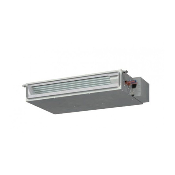
[ II Components and Functions ] II Components and Functions [1] Components and Functions 1. Indoor (Main) Unit - 2 - HWE1209A... -
Page 7: Specfications
[ III Specfications ] III Specfications [1] Specifications 1. Specfications Model PEFY- PEFY- PEFY- PEFY- WP10VMS1-E WP15VMS1-E WP20VMS1-E WP25VMS1-E Power supply Voltage 220-240 Frequency 50/60 Cooling capacity Heating capacity Power consumption Cooling 0.030 0.050 0.051 0.060 Heating 0.030 0.030 0.031 0.040 Current consumption Cooling... - Page 8 [ III Specfications ] Model PEFY-WP32VMS1-E PEFY-WP40VMS1-E PEFY-WP50VMS1-E Power supply Voltage 220-240 Frequency 50/60 Cooling capacity Heating capacity Power consumption Cooling 0.071 0.090 0.090 Heating 0.051 0.070 0.070 Current consumption Cooling 0.61 0.73 0.77 Heating 0.50 0.62 0.66 External finish (Munsel No.) Galvanized Dimensions Height...
-
Page 9: Electrical Component Specifications
[ III Specfications ] 2. Electrical component specifications Component Sym- PEFY- PEFY- PEFY- PEFY- WP10VMS1-E WP15VMS1-E WP20VMS1-E WP25VMS1-E Room temperature TH21 Resistance 0°C/15k , 10°C/9.6k , 20°C/6.3k , 25°C/5.4k , 30°C/4.3k , 40°C/3.0k thermistor Water inlet pipe therm- TH22 Resistance 0°C/15k , 10°C/9.6k , 20°C/6.3k , 25°C/5.4k , 30°C/4.3k , 40°C/3.0k istor Water outlet pipe... -
Page 10: Outlines And Dimensions
[ IV Outlines and Dimensions ] IV Outlines and Dimensions [1] Outlines and Dimensions 1. PEFY-WP10, 15, 20, 25, 32, 40, 50VMS1-E Unit : mm Space required for service and maintenance. Provide an access door for maintenance at the bottom. Note 1 Use M10 screw for the suspension bolt (field supply). - Page 11 [ IV Outlines and Dimensions ] Unit : mm - 7 - HWE1209A...
-
Page 12: Wiring Diagram
[ V Wiring Diagram ] V Wiring Diagram [1] Wiring Diagram 1. PEFY-WP10, 15, 20, 25, 32, 40, 50VMS1-E - 8 - HWE1209A... - Page 13 [ V Wiring Diagram ] Table.1 SYMBOL EXPLANATION SYM- NAME SYM- NAME SYM- NAME I.B. Indoor control board CN32 Connector (Remote switch) Switch (function setting) (I.B.) A.B. Address board CN41 Connector (HA terminal-A) Switch (function setting) (I.B.) Power supply terminal block CN51 Connector (Centralized con- Connector (emergency opera-...
-
Page 14: Refrigerant System Diagram
[ VI Refrigerant System Diagram ] VI Refrigerant System Diagram [1] Refrigerant system diagram Water outlet thermistor TH23 Water outlet Water inlet Screw connections Water inlet thermistor TH22 Heat exchanger Manual air purge valve Room temperature thermistor TH21 Capacity PEFY-WP10, 15, 20, 25, 32, 40, 50VMS1-E Water outlet Rc3/4 screw Water inlet... -
Page 15: Troubleshooting
[ VII Troubleshooting ] VII Troubleshooting [1] Troubleshooting 1. Check methods 1. Component and check points (1) Thermistor Room temperature thermistor (TH21) Water inlet thermistor (TH22) Water outlet thermistor (TH23) Disconnect the connector and measure the resistance between terminals with a tester. (Ambient temperature 10°C - 30°C) Normal Abnormal... - Page 16 [ VII Troubleshooting ] (4) Drain float switch (CN4F) Disconnect the connector, and measure the resistance between terminals with a tester. Moving part Switch Magnet Position of the moving part Normal Abnormal Short (any position but short) Down Open (any position but open) - 12 - HWE1209A...
-
Page 17: Dc Fan Motor (Fan Motor/Indoor Control Board)
[ VII Troubleshooting ] 2. DC fan motor (fan motor/indoor control board) 1. CAUTION A high voltage is applied to the connector for connection to the fan motor (CNMF). Do not unplug the connector CNMF with the unit energized to avoid damage to the indoor control board and fan motor. 2. -
Page 18: Address Switch Setting
[ VII Troubleshooting ] 3. Address switch setting Make sure that power to the unit is turned off. 9 10 Indoor unit control board Factory setting (all models) 1. When using an ME remote controller, set the address with the rotary switches (SW11, SW12). Address setting is not required when the unit remote controller is used. -
Page 19: Voltage Test Points On The Control Board
[ VII Troubleshooting ] 4. Voltage test points on the control board Fuse Fuse(AC 250V 6.3A) Power supply voltage (220 - Fuse 240VAC) CN2M For M-NET transmission cable connection (24 - 30VDC) Emergency operation Capacity setting Function setting CN42 For address board connection Function setting CN81 For address board connection... -
Page 20: Dipswitch Setting (Factory Setting)
[ VII Troubleshooting ] 5. Dipswitch setting (Factory setting) 1. Function setting (1) SW1 Switch position Function Switch setting Active Thermistor (Intake air Built-in thermistor on the remote Indoor unit thermistor) controller Filter clogging detection Available Unavailable Filter life 2500 hr 100 hr Outdoor air intake Enabled... - Page 21 [ VII Troubleshooting ] 2. Capacity code setting (1) SW2 1) Indoor control board Dipswitch settings must be made while the unit is stopped. Factory setting The switches are set to correspond to the unit capacity. PEFY-WP10VMS1-E PEFY-WP15VMS1-E PEFY-WP20VMS1-E PEFY-WP25VMS1-E PEFY-WP32VMS1-E PEFY-WP40VMS1-E PEFY-WP50VMS1-E...
-
Page 22: Instructions For Debris Removal Operation
[ VII Troubleshooting ] 6. Connection No. setting (1) SW14 (Rotary switch) This switch is used when the unit connected to an R2 series of outdoor unit. 1) Address board Factory setting Note: Changes to the dipswitches SW11, SW12, SW14, and SW15 must be made while the unit is stopped and the remote controller is OFF. -
Page 23: Disassembly Procedure
[ VIII Disassembly Procedure ] VIII Disassembly Procedure [1] Disassembly Procedure 1. Control box Exercise caution when removing heavy parts. 1. Removing the control box cover (1) Remove the two fixing screws on the cover (A) to remove Fig.1 Fig.2 - 19 - HWE1209A... -
Page 24: Thermistor (Intake Air)
[ VIII Disassembly Procedure ] 2. Thermistor (Intake air) Exercise caution when removing heavy parts. 1. Remove the control box cover according to the procedure in section 1. 2. Remove the thermistor. (1) Remove the two fixing screws on the metal base (B) to re- move it. -
Page 25: Drainpan
[ VIII Disassembly Procedure ] 3. Drainpan Exercise caution when removing heavy parts. 1. Removing the filter and the bottom plate (1) Push down the tab on the filter, and pull out the filter in the direction of the arrow 1. (2) Remove the fixing screws on the bottom plate (D), (E) to remove it. -
Page 26: Thermistor (Water Outlet) (Water Inlet)
[ VIII Disassembly Procedure ] 4. Thermistor (Water outlet) (Water inlet) Exercise caution when removing heavy parts. 1. Remove the drain pan according to the procedure in sec- tion 3. 2. Removing the Heat exchanger cover (1) Remove the four fixing screws on the heat exchanger cov- er (F) to remove it. -
Page 27: Fan And Fan Motor
[ VIII Disassembly Procedure ] 5. Fan and fan motor Exercise caution when removing heavy parts. 1. Removing the filter and the bottom plate (1) Push down the tab on the filter, and pull out the filter in the direction of the arrow 1. (2) Remove the fixing screws on the bottom plate (J) to re- move it. -
Page 28: Bearing
[ VIII Disassembly Procedure ] 6. Bearing P40, P50, P63 models only. Exercise caution when removing heavy parts. 1. Removeing the bearing (1) Remove the two fixing screws on the bearing cover (M) to remove it. Fig.14 (2) Remove the two bearing retainer screws to remove the bearing. -
Page 29: Heat Exchanger
[ VIII Disassembly Procedure ] 7. Heat exchanger Exercise caution when removing heavy parts. 1. Remove the drain pan according to the procedure in section 2. Remove the heat exchanger cover according to the proce- dure in section 4 2. 3. -
Page 30: Drain Pump
[ VIII Disassembly Procedure ] 8. Drain pump Exercise caution when removing heavy parts. 1. Remove the drain pan according to the procedure in section 2. Removing the air-vent pipe (1) Remove the air-vent pipe (a) from the cable strap (b). Fig.18 3. -
Page 31: Float Switch
[ VIII Disassembly Procedure ] 9. Float Switch Exercise caution when removing heavy parts. 1. Remove the drain pan according to the procedure in section 2. Removing the air-vent pipe (1) Remove the air-vent pipe (a) from the cable strap (b). Fig.20 3. - Page 32 New publication, effective Mar. 2017 Mar. 2017 HWE1209A Printed in Japan Specifications subject to change without notice...
- Page 33 Related Links Model Number: PEFY-WP20VMS1-E Hotel du Vin, Hybrid VRF, Warwickshire Hybrid VRF Brochure J D Wetherspoon Hotel, Hybrid VRF, Cambridgeshire PEFY-WP10-50VMS1-E (HVRF) Product Information Sheet PEFY-WP15-50VMS1-E Declaration of Conformity PEFY-WP15-50VMS1-E Installation Manual (KD79H957H01) PEFY-WP15-50VMS1-E Instruction Book (KD79H961H01) PEFY-WP15-50VMS1-E Parts Catalogue (BWE01301C) PEFY-WP15-50VMS1-E Service Manual (HWE1209A) Strand Palace, Hybrid VRF, London Trafalgar House, Hybrid VRF, Leeds...