Table of Contents
Table of Contents

Related Manuals for Yamaha M3000A


Summary of Contents for Yamaha M3000A
- Page 1 Owner’s Manual Mode d’emploi Bedienungsanleitung...
- Page 2 300 ohm ribbon lead, change the lead-in to coaxial type cable. If these corrective measures do not produce satisfactory results, please contact the local retailer authorized to distribute this type of product. If you can not locate the appropriate retailer, please contact Yamaha Corporation of America, Electronic Service Division, 6600 Orangethorpe Ave, Buena Park, CA 90620 The above statements apply ONLY to those products distributed by Yamaha Corporation of America or its subsidiaries.
-
Page 3: Table Of Contents
Contents Features of the system...5 Control panel...6 Input channel section... 6 Variable/fixed select section... 13 Mix section ... 14 VCA master fader section ... 16 STEREO A section... 16 STEREO B section... 18 Monitor section... 19 Talkback section ... 21 Meter select section ... - Page 4 Precautions • Connect the mixer power cord only to the power supply unit, and connect the power supply unit to an AC outlet of the type stated in this Owner’s Manual or as marked on the power supply unit. Failure to do so is a fire and electrical shock hazard.
-
Page 5: Features Of The System
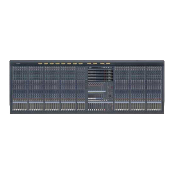
M3000A-24 provides 24 monaural). Stereo out- put, 16 mix outputs, and 8 matrix outputs are pro- vided in addition. The M3000A is suitable for use in a wide range of applications, such as the main mixer for sound reinforcement, as a monitor mixer, or in build- ing installations. -
Page 6: Control Panel
–15 –15 M13/ M15/ Mono input channels The M3000A-56C provides 56 input channels, the M3000A-40C provides 40 input channels, the M3000A-32 provides 32 input channels, and the M3000A-24 provides 24 input channels. All input channels have the same specifications. A Phantom power switch/ +48 V indicator This switch turns the +48 V phantom power on/off for each channel. - Page 7 I M1–M8 switches These switch on/off the signal which is sent from the input channel to MIX buses 1–8. Note: If these switches are off, no signal will be sent to the corresponding MIX bus from this input channel, regardless of the switch setting of the vari- able/fixed select section (page 13).
- Page 8 ST bus. S ON/EDIT switch/ ON , CHECK indicators The function of this switch and these indicators will depend on the mode of the M3000A. In normal mode The ON/EDIT switch will turn on the input channel.
-
Page 9: Channel Fader
U VCA GROUP select switches These switches select the VCA master fader(s) which will control the signal output level of this channel. When you select a VCA group 1–8, the indicator located at the left of each switch will light, and the corresponding VCA master fader (VCA master section 3) will control the channel. -
Page 10: Stereo Input Channels
M13/ M15/ Stereo input channels The M3000A provides four stereo input channels. Ste- reo sound sources such as sub-mixers, effect proces- sor, or CD players can be input to the INPUT A jacks (XLR connectors) or INPUT B jacks (RCA phono connectors) located on the rear panel. - Page 11 G M1–M8 mix level controls These controls combine the stereo signal from the ste- reo input channel into a mono signal, and send it to MIX buses 1–8. When the control is in the “ ” posi- tion, the level is nominal (0 dB). Use the PRE switch (M) to switch between pre/post fader.
- Page 12 ST bus. P ON/EDIT switch/ON, CHECK indicators The function of this switch and these indicators will depend on the mode of the M3000A. In normal mode The ON/EDIT switch will turn on the stereo input channel.
-
Page 13: Variable/Fixed Select Section
Variable/fixed select section The M3000A’s GA (Group/Aux) diversity function allows MIX buses 1–8 to function either as group buses or as AUX buses. In this section, you can switch each pair of MIX buses (1/2, 3/4, 5/6, 7/8) between functioning as group buses or as AUX buses. -
Page 14: Mix Section
MIX OUT will be sent to the ST bus. D ON/EDIT switches The function of these switches and indicators will depend on the mode of the M3000A. The ON/EDIT switches will turn each MIX OUT on/ off. When on, the ON indicator will light. MIX OUTs which are turned off will send no signal to the MIX OUT 1–16 jacks, the MAS AFL bus, the ST bus or the... - Page 15 MIX buses 1–8 (VARIABLE) (FIX) 11 13 15 1 2 3 4 5 6 7 8 10 12 14 16 VARIABLE MIX buses 9–12 (VARIABLE) (FIX) 11 13 15 1 2 3 4 5 6 7 8 10 12 14 16 from Ctrl Master MIX buses 13–16 (VARIABLE)
-
Page 16: Vca Master Fader Section
Control panel VCA master fader section The VCA master fader section allows the gain of input channels assigned to a VCA group to be controlled as a whole by the corresponding VCA fader. The VCA group(s) to which each input channel is assigned is specified by the VCA GROUP select switches (mono input channels (U), stereo input channels R). - Page 17 B ON/EDIT switch The function of this switch and indicator will depend on the mode of the M3000A. In normal mode The ON/EDIT switch will turn ST OUT A on/off. When on, the ON indicator will light. When off, no...
-
Page 18: Stereo B Section
Control panel STEREO B section This section controls the signal which is output from the rear panel ST OUT B jacks (page 27) Note: This section is not affected by the on/off switching of scene memory. LEVEL STEREO B A LEVEL control This controls the output level of the signal which is sent from the ST OUT B jacks. -
Page 19: Monitor Section
Monitor section INPUT MASTER MASTER 2TR IN In this section you can select the signal which will be monitored from the MONITOR OUT jacks and the PHONES jack. The following signals can be selected as monitor sources. Signals which can be selected as monitor sources Signals MASTER... -
Page 20: Phones Jack
Control panel LEVEL MONITOR PHONES to Meter INSERT I/O L INSERT I/O R CHECK ON CONTROL ON/EDIT G LEVEL control This control adjusts the level of the signal which is output from the MONITOR OUT jacks. It does not affect the PHONES jack. H ON switch This is an on/off switch for the signal which is output from the MONITOR OUT jacks. -
Page 21: Talkback Section
Talkback section M1-M2 M3-M4 M5-M6 M7-M8 M9-M12 M13-M16 PINK 10kHz 1kHz 100Hz OFF/ OSCILLATOR LEVEL TALKBACK A M1–M2 switch B M3–M4 switch C M5–M6 switch D M7–M8 switch E M9–M12 switch F M13–M16 switch G ST switch These switches send the talkback or test tone oscillator signal to MIX buses 1–2, MIX buses 3–4, MIX buses 5–6, MIX buses 7–8, MIX buses 9–12, MIX buses 13–... -
Page 22: Meter Select Section
Control section On the M3000A, on/off settings for the mono/stereo input channels, the output channels of the mix sec- tions, and STEREO A OUT can be stored as a “scene”... - Page 23 A UTILITY switch Press this switch to enter Utility mode, where you can make settings for scene memories and MIDI, etc. When you are in Utility mode (refer to page 34), the indicator located above the switch will light. B RECALL switch Use this switch to recall scenes from scene memory.
-
Page 24: Matrix Section
Control panel Matrix section The M3000A provides eight matrices which allow output signals from the MIX buses 1–16 or the ST bus, or input signals from MATRIX SUB IN to be mixed at the desired level. Matrix 1–8 are output in mono from MATRIX OUT jacks 1-8 respectively (page 27), and can be used as foldback or for an individual monitor system. -
Page 25: Meter Bridge
Meter bridge PEAK PEAK – – – M1/M9/MATRIX 1 IX 7 M8/M16/MATRIX 8 A M1/M9/MATRIX1–M8/M16/MATRIX8 level meters As selected by the switch settings of the METER SEL section (page 22), these meters indicate the output levels of MIX OUT 1–8/MIX OUT 9–16/MATRIX OUT 1–8. -
Page 26: Rear Panel
Rear panel Mono input channel input/out- put jacks ST CH 2 ST CH 1 INPUT A INPUT A INPUT INPUT INPUT INPU DIRECT OUT DIRECT OUT DIRECT OUT DIRECT 0 dB 0 dB 0 dB 0 dB INSERT I/O INSERT I/O INSERT I/O INSERT INPUT B... -
Page 27: Master Section Input/Output Jacks
Master section input/output jacks MIDI CONTROL PHANTOM MASTER THRU EXTERNAL I/O MASTER SLAVE MASTER/SLAVE CUE CONTROL DC POWER INPUT F MIX INSERT I/O jacks These are TRS phone jacks for inserting external sig- nal processors into MIX buses 1–16. Nominal input/ output level is 0 dB. - Page 28 VCA control functionality of the other device to which this connector is connected to be controlled from a single console. If the M3000A is to be the mas- ter for the VCA control, set the VCA MASTER/SLAVE switch (N) to the MASTER position. If the M3000A is to be the slave, set the VCA MASTER/SLAVE switch to the SLAVE position.
-
Page 29: Output Connector For Illumination Power Supply
If two or more M3000A consoles are connected via MIDI, a scene selection on one M3000A can simultaneously switch the scene on the other M3000A(s). -
Page 30: About The Ga Diversity Functionality
About the GA Diversity functionality The GA Diversity functionality of the M3000A allows you to switch the MIX buses 1–8 between acting as group buses (output level from the input channels will be fixed) or acting as AUX buses (output level from the input channels will be variable). -
Page 31: About The Scene Memory Function
When the M3000A is in Check mode, the indi- cator of the CHECK switch in the control section will light. -
Page 32: Operations In Normal Mode
About the Scene Memory function Operations in normal mode Storing a scene (normal mode) 1. Make sure that the M3000A is in normal mode, and use the ON/EDIT switches of the mono/ste- reo input channels, the mix section and the STE- REO A section to make the desired on/off settings. -
Page 33: Operations In Check Mode
CHECK switch in the control section. Verifying a scene before you recall (Check mode) 1. If the M3000A is in normal mode, press the con- trol section CHECK switch. The CHECK switch LED will light, and the M3000A will enter check mode. -
Page 34: Operations In Utility Mode
Bulk Out and Bulk Dump Request are also per- formed in this mode. Basic operation in utility mode 1. When the M3000A is in normal mode, press and immediately release the control section UTILITY switch. The UTILITY switch indicator will light, and the M3000A will enter utility mode. -
Page 35: Control Change Table
105–112 can also be used to switch mute groups 1–8 on/off.) Also, when the ON/EDIT switches of the M3000A are oper- ated, the corresponding control change will be trans- mitted. If this is set to “... -
Page 36: Using Mute Groups
About the Scene Memory function Control No. ON/EDIT Switch Control No. CH INPUT 56 MIX 1 OUT MIX 2 OUT MIX 3 OUT MIX 4 OUT MIX 5 OUT MIX 6 OUT MIX 7 OUT MIX 8 OUT STEREO A OUT MIX 9 OUT MIX 10 OUT MIX 11 OUT... -
Page 37: About The Local Control Circuit
DIRECT MUTE RECALL 1–8 switches will be defeated. About the local control circuit If an error occurs in the system of the M3000A, the on/off control of each input channel and bus will CHECK CHECK... -
Page 38: About The Vca Functionality
About the VCA functionality The VCA master section of the M3000A contains eight VCA master faders. These VCA master faders 1–8 can be used to control the overall input level of input channels assigned to the corresponding VCA groups 1–8. - Page 39 Using two or more VCA master faders to control a single channel As the opposite of the example on the previous page, it is also possible to assign a channel to two or more VCA groups. The following diagram shows an exam- ple of signal flow when channel 1 is assigned to VCA groups 1, 5, and 8.
- Page 40 About the VCA functionality • If the VCA MUTE switch of a VCA master fader is turned on (the indicator beside the switch will light), the post-fader signal of all input channels assigned to that VCA group will be muted. This is convenient when you wish to simultaneously mute or un-mute multiple channels without operating the faders.
-
Page 41: Error Messages
Error messages One of the following error messages may appear in the MEMORY display while operating the M3000A or when the power is turned on. If this occurs, refer to the following explanations and take the appropriate action. An error occurred while receiving MIDI data. -
Page 42: Specifications
Specifications General specifications 0 dB is referenced to 0.775 Vrms. Total Harmonic Distortion Less than 0.1% (THD+N) (Master output) 20 Hz–20 kHz @ +14 dB 600 Frequency Response 0+1, –3 dB (Master Output) 20 Hz–20 kHz @ +4 dB 600 Hum &... -
Page 43: Input/Output Characteristics
Input/output characteristics Input specifications Gain Actual Load Connection Trim Impedance –60 CH INPUT (1~24) (1~32) (1~40) (1~56) –16 –30 ST CH A INPUT [L, R] (1~4) –20 ST CH B INPUT 10 k [L, R] (1~4) TALKBACK IN 10 k 2TR IN 1 [L, R] 10 k 2TR IN 2 [L, R]... -
Page 44: Other
Specifications Other Connector wiring DC POWER INPUT Pin No. Signal name Power supply remote +15 V 15 V GND +48 V GND –15 V +12 V +12V GND/ power supply remote Power supply remote +48 V FRAME GND VCA EXTERNAL I/O Pin No. -
Page 45: Dimensions
Dimensions Units: mm... -
Page 46: Midi Data Format
The following bulk messages can be transmitted and received. (1) SCENE MEMORY No. BULK OUT FORMAT STATUS 11110000 F0h System Exclusive Message ID No. 01000011 43h Manufacturer's ID No.(YAMAHA) SUB STATUS 0000xxxx 0nh n=0~15(MIDI Channel) FORMAT No. 01111110 7Eh Universal Bulk Dump BYTE COUNT(HIGH) 00000000 00h 39(29+10)bytes... -
Page 47: Midi Implementation Chart
YAMAHA [MIXING CONSOLE] Model : M3000A IDI Implementation Function... Basic Default Chart Channel Changed Default Mode Messages Altered Note Number : True voice Velocity Note ON Note OFF After Key's Touch Ch's Pitch Bend 1-69 Control Change 73-78 105-112 Program...