Table of Contents
Quick Links
www.ti.com
User's Guide
MCT8316ZTEVM Evaluation Module
This document is provided with the MCT8316ZT customer evaluation module (EVM) as a supplement to the
MCT8316Zx data sheet
(MCT8316Z Three-Phase Sensored-Trapezoidal BLDC Motor Driver Data
User's Guide details the hardware implementation of the EVM and how to setup and power the board.
Warnings..........................................................................................................................................................2
2
Introduction.............................................................................................................................................................................3
Guide....................................................................................................................................................................4
4.2 Connection Details.............................................................................................................................................................
4.3 MSP430FR2355 Microcontroller........................................................................................................................................
Lights..........................................................................................................................................................................8
4.5 User-Configurable Settings................................................................................................................................................
Settings................................................................................................................................................11
5 Hardware Setup....................................................................................................................................................................
Application.............................................................................................................................................14
6.1 Downloading Code Composer Studio and Importing GUI Code......................................................................................
6.2 Using the eZ-FET to Program the MSP430FR2355........................................................................................................
6.3 Importing GUI into GUI Composer...................................................................................................................................
GUI......................................................................................................................................................17
7
Schematics............................................................................................................................................................................18
7.1 Main Supply and Pi Filter.................................................................................................................................................
Interface.................................................................................................................................................18
7.3 USB to UART...................................................................................................................................................................
7.5 MSP430FR2355 MCU.....................................................................................................................................................
7.7 3.3V Buck Regulator........................................................................................................................................................
7.8 Status LEDs.....................................................................................................................................................................
Settings................................................................................................................................................22
7.10 Switches and PWM Input...............................................................................................................................................
8 Revision History...................................................................................................................................................................
Figure 3-1. Reference for Quick Start Guide...............................................................................................................................
Figure 4-1. MCT8316ZTEVM Major Hardware Blocks................................................................................................................
Figure 4-2. Connections from Motor to MCT8316ZTEVM...........................................................................................................
Figure 6-1. MCT8316ZTEVM GUI Code in Code Composer Studio.........................................................................................
Figure 6-3. MCT8316ZTEVM GUI ............................................................................................................................................
Figure 7-2. Connectors and Interface Schematic......................................................................................................................
Schematic.........................................................................................................................................19
SNLU291A - MARCH 2021 - REVISED JUNE 2021
Submit Document Feedback
Table of Contents
Overview.........................................................................................................................................5
MCT8316ZTEVM.......................................................................................................5
Debug........................................................................................................................................19
List of Figures
MCT8316ZTEVM............................................................................................7
MCT8316ZTEVM.............................................................................................................8
LEDs.............................................................................................................................................9
™
Schematic.......................................................................................................................18
Copyright © 2021 Texas Instruments Incorporated
ABSTRACT
Driver.......................................................................................20
View)........................................................................................3
Variant)................................................................................11
.................................................................16
Table of Contents
Sheet). This
MCT8316ZTEVM Evaluation Module
5
7
9
13
14
15
16
18
19
20
21
21
22
22
4
5
6
15
17
18
1
Table of Contents

Related Manuals for Texas Instruments MCT8316ZT


Summary of Contents for Texas Instruments MCT8316ZT
-
Page 1: Table Of Contents
Table of Contents User’s Guide MCT8316ZTEVM Evaluation Module ABSTRACT This document is provided with the MCT8316ZT customer evaluation module (EVM) as a supplement to the MCT8316Zx data sheet (MCT8316Z Three-Phase Sensored-Trapezoidal BLDC Motor Driver Data Sheet). This User's Guide details the hardware implementation of the EVM and how to setup and power the board. -
Page 2: Cautions And Warnings
Table 4-1. Description of MCT8316ZTEVM LEDs (default in bold after powerup)..............Table 4-2. Description of User-Selectable Settings on MCT8316ZTEVM (Default in Bold)............9 Table 4-3. User-Adjustable Resistor Divider Settings for MCT8316ZT Variant (Defaults in Bold)..........Table 6-1. SPI-by-Wire Connections Needed to Program MSP430FR2355................15... -
Page 3: Introduction
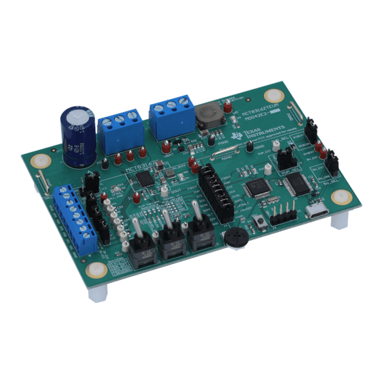
This document serves as a startup guide to supplement the MCT8316ZTEVM. It is intended for engineers to design, implement, and validate reference hardware for the MCT8316ZT (H/W variant) along with the device data sheet. Figure 2-1. MCT8316ZTEVM Printed Circuit Board (PCB - Top View) SNLU291A –... -
Page 4: Quick Start Guide
Optionally, use the GUI (as shown in Section 6) to monitor real-time speed of the motor, put the MCT8316ZT into a low-power sleep mode, and read status of the LEDs. Figure 3-1. Reference for Quick Start Guide MCT8316ZTEVM Evaluation Module SNLU291A –... -
Page 5: Hardware And Software Overview
HPx and HNx pins for each respective phase and remove jumpers J8-10. Otherwise, if using single-ended input from a Hall sensor, connect to only the HPx pins for each phase and populate jumpers R8–R10. SNLU291A – MARCH 2021 – REVISED JUNE 2021 MCT8316ZTEVM Evaluation Module Submit Document Feedback Copyright © 2021 Texas Instruments Incorporated... -
Page 6: Figure 4-2. Connections From Motor To Mct8316Ztevm
PC and the 3.3 V from the FTDI chip is limit to 30 mA. If the user wishes to supply more current to these rails, they may use the 5V_SEL jumper J3 and 3V3_SEL jumper J5 to connect external power rails. MCT8316ZTEVM Evaluation Module SNLU291A – MARCH 2021 – REVISED JUNE 2021 Submit Document Feedback Copyright © 2021 Texas Instruments Incorporated... -
Page 7: Msp430Fr2355 Microcontroller
This allows for microcontroller signal debugging or using the MCT8316ZTEVM as a standalone gate driver with an external microcontroller. SNLU291A – MARCH 2021 – REVISED JUNE 2021 MCT8316ZTEVM Evaluation Module Submit Document Feedback Copyright © 2021 Texas Instruments Incorporated... -
Page 8: Led Lights
Motor power is supplied to the board Green Used for UART or debugging MSP_LED0 MSP_LED1 Used for UART or debugging MCT8316ZTEVM Evaluation Module SNLU291A – MARCH 2021 – REVISED JUNE 2021 Submit Document Feedback Copyright © 2021 Texas Instruments Incorporated... -
Page 9: User-Configurable Settings
Enables pullup on Hall positive A J8 is inserted Pullup, use for (HPA) Digital Hall inputs J8 is removed Floating, use for Analog Hall inputs SNLU291A – MARCH 2021 – REVISED JUNE 2021 MCT8316ZTEVM Evaluation Module Submit Document Feedback Copyright © 2021 Texas Instruments Incorporated... - Page 10 (ILIM voltage limit 10 kΩ (R11) of AVDD to AVDD - 0.4 sets limit proportionally from 0 to 8 A) MCT8316ZTEVM Evaluation Module SNLU291A – MARCH 2021 – REVISED JUNE 2021 Submit Document Feedback Copyright © 2021 Texas Instruments Incorporated...
-
Page 11: Hardware Variant Settings
The MCT8316ZT device uses the configurable resistors to control the MODE, SLEW, ADVANCE, and VSEL_BUCK settings. When using the MCT8316ZT, the SPI enable resistors in the “Depop. if H/W Variant” silk screen box are to be depopulated (R13–R16) and the resistor dividers in the “H/W Variant Resistors” silk screen box are populated with the desired settings (R19–R22 and R26–R29). -
Page 12: Table 4-3. User-Adjustable Resistor Divider Settings For Mct8316Zt Variant (Defaults In Bold)
Hardware and Software Overview www.ti.com Table 4-3. User-Adjustable Resistor Divider Settings for MCT8316ZT Variant (Defaults in Bold) Setting Name Description Resistors Configuration Setting (AVDD and AGND) VSEL_BK V Buck regulator average R21 and R28 R28 = 0 Ω 3.3 V... -
Page 13: Hardware Setup
If using the MCT8316ZTEVM with an external microcontroller, remove all shunt jumpers from jumper bridge J6. Connect with external jumpers to the left side of the jumper bridge from the external MCU. SNLU291A – MARCH 2021 – REVISED JUNE 2021 MCT8316ZTEVM Evaluation Module Submit Document Feedback Copyright © 2021 Texas Instruments Incorporated... -
Page 14: Firmware And Gui Application
5. Select the “MCT8316ZTEVM_MSP430FR2355_Firmware_GUI” folder installed from step 1. 6. Import the project “MCT8316ZTEVM_MSP430FR2355_Firmware_GUI” into your workspace as shown in Figure 6-1. MCT8316ZTEVM Evaluation Module SNLU291A – MARCH 2021 – REVISED JUNE 2021 Submit Document Feedback Copyright © 2021 Texas Instruments Incorporated... -
Page 15: Using The Ez-Fet To Program The Msp430Fr2355
Table 6-1. SPI-by-Wire Connections Needed to Program MSP430FR2355 ™ MSP430 LaunchPad (eZ-FET Debug Probe Side) (J101) MCT8316ZTEVM 4-pin SPI-by-Wire Header (J4) 3.3V SBWTDIO SBWTDIO SBWTCK SBWTCK SNLU291A – MARCH 2021 – REVISED JUNE 2021 MCT8316ZTEVM Evaluation Module Submit Document Feedback Copyright © 2021 Texas Instruments Incorporated... -
Page 16: Importing Gui Into Gui Composer
3. Once the project is loaded, click on the Play button () to launch the MCT8316ZTEVM GUI as shown in Figure 6-3. MCT8316ZTEVM Evaluation Module SNLU291A – MARCH 2021 – REVISED JUNE 2021 Submit Document Feedback Copyright © 2021 Texas Instruments Incorporated... -
Page 17: Mct8316Ztevm Gui
To place the MCT8316Z into a low-power sleep mode, click the nSLEEP button into the right position. The MSP430 sends an active-low signal to nSLEEP on the device. SNLU291A – MARCH 2021 – REVISED JUNE 2021 MCT8316ZTEVM Evaluation Module Submit Document Feedback Copyright © 2021 Texas Instruments Incorporated... -
Page 18: Schematics
7.1 Main Supply and Pi Filter Figure 7-1. Main Supply and Pi Filter Schematic 7.2 Connectors and Interface Figure 7-2. Connectors and Interface Schematic MCT8316ZTEVM Evaluation Module SNLU291A – MARCH 2021 – REVISED JUNE 2021 Submit Document Feedback Copyright © 2021 Texas Instruments Incorporated... -
Page 19: Usb To Uart
7.3 USB to UART Figure 7-3. USB to UART Schematic 7.4 MCU Programming and Debug Figure 7-4. MCU Programming and Debug Schematic SNLU291A – MARCH 2021 – REVISED JUNE 2021 MCT8316ZTEVM Evaluation Module Submit Document Feedback Copyright © 2021 Texas Instruments Incorporated... -
Page 20: Msp430Fr2355 Mcu
7.5 MSP430FR2355 MCU Figure 7-5. MSP430FR2355 MCU Schematic 7.6 MCT8316ZT 3-Phase Sensored Trapezoidal Integrated Driver Figure 7-6. MCT8316ZT 3-Phase Sensored Trapezoidal Integrated Driver Schematic MCT8316ZTEVM Evaluation Module SNLU291A – MARCH 2021 – REVISED JUNE 2021 Submit Document Feedback Copyright © 2021 Texas Instruments Incorporated... -
Page 21: Buck Regulator
Schematics 7.7 3.3V Buck Regulator Figure 7-7. 3.3V Buck Regulator Schematic 7.8 Status LEDs Figure 7-8. Status LED Schematics SNLU291A – MARCH 2021 – REVISED JUNE 2021 MCT8316ZTEVM Evaluation Module Submit Document Feedback Copyright © 2021 Texas Instruments Incorporated... -
Page 22: Hardware Variant Settings
Changes from Revision * (March 2021) to Revision A (June 2021) Page • Added Cautions and Warnings section.......................2 • Corrected equation............................MCT8316ZTEVM Evaluation Module SNLU291A – MARCH 2021 – REVISED JUNE 2021 Submit Document Feedback Copyright © 2021 Texas Instruments Incorporated... - Page 23 STANDARD TERMS FOR EVALUATION MODULES Delivery: TI delivers TI evaluation boards, kits, or modules, including any accompanying demonstration software, components, and/or documentation which may be provided together or separately (collectively, an “EVM” or “EVMs”) to the User (“User”) in accordance with the terms set forth herein.
- Page 24 www.ti.com Regulatory Notices: 3.1 United States 3.1.1 Notice applicable to EVMs not FCC-Approved: FCC NOTICE: This kit is designed to allow product developers to evaluate electronic components, circuitry, or software associated with the kit to determine whether to incorporate such items in a finished product and software developers to write software applications for use with the end product.
- Page 25 www.ti.com Concernant les EVMs avec antennes détachables Conformément à la réglementation d'Industrie Canada, le présent émetteur radio peut fonctionner avec une antenne d'un type et d'un gain maximal (ou inférieur) approuvé pour l'émetteur par Industrie Canada. Dans le but de réduire les risques de brouillage radioélectrique à...
- Page 26 www.ti.com EVM Use Restrictions and Warnings: 4.1 EVMS ARE NOT FOR USE IN FUNCTIONAL SAFETY AND/OR SAFETY CRITICAL EVALUATIONS, INCLUDING BUT NOT LIMITED TO EVALUATIONS OF LIFE SUPPORT APPLICATIONS. 4.2 User must read and apply the user guide and other available documentation provided by TI regarding the EVM prior to handling or using the EVM, including without limitation any warning or restriction notices.
- Page 27 Notwithstanding the foregoing, any judgment may be enforced in any United States or foreign court, and TI may seek injunctive relief in any United States or foreign court. Mailing Address: Texas Instruments, Post Office Box 655303, Dallas, Texas 75265 Copyright © 2019, Texas Instruments Incorporated...
- Page 28 TI products. TI’s provision of these resources does not expand or otherwise alter TI’s applicable warranties or warranty disclaimers for TI products.IMPORTANT NOTICE Mailing Address: Texas Instruments, Post Office Box 655303, Dallas, Texas 75265 Copyright © 2021, Texas Instruments Incorporated...