Table of Contents
Quick Links
This user's guide describes the characteristics, operation, and use of the TPS630702EVM evaluation
module (EVM). The TPS630702EVM is designed to help the users easily evaluate and test the operation
and functionality of the TPS630702 Buck-Boost Converter. The TPS630702EVM uses the TPS630702
adjustable version with output discharge function. The output voltage is set to 3.3 V to 5 V. The user can
select the output voltage with the VSEL pin. The EVM operates from 2 V to 16 V input voltage. Output
currents can go up to 2 A in buck mode and boost mode. This document includes setup instructions for
the hardware, a schematic diagram, a bill of materials (BOM), and printed-circuit board (PCB) layout
drawings for the evaluation module. Throughout this document, the abbreviations EVM, TPS630702EVM,
and the term evaluation module are synonymous with the TPS630702, unless otherwise noted.
...................................................................................................................
1
1.1
1.2
1.3
..........................................................................................................................
2
2.1
2.2
Setup
3
3.1
4
4.1
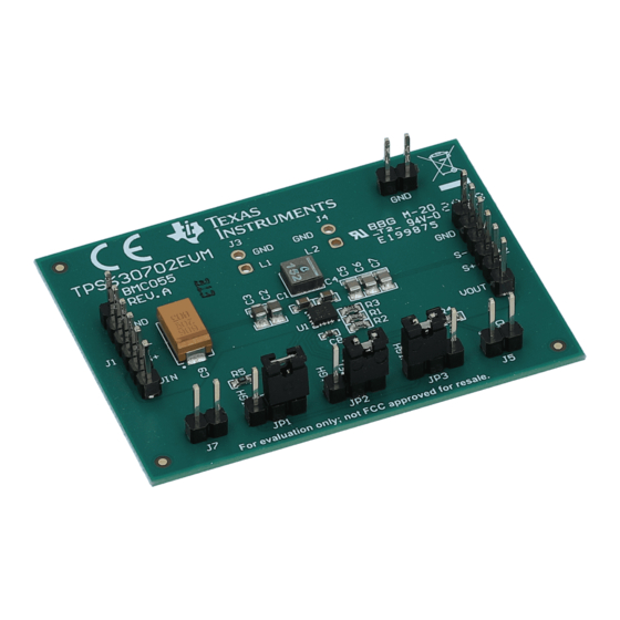
Figure 1. TPS63802 EVM Picture
..........................................................................................................
.........................................................................................
.........................................................................................................
.................................................................................................................
.................................................................................................................
...........................................................................................
............................................................................................
.......................................................................................
Copyright © 2019, Texas Instruments Incorporated
TPS630702EVM User's Guide
Contents
..............................................................
User's Guide
SLVUBR1 - August 2019
TPS630702EVM User's Guide
2
2
3
3
3
3
4
5
5
8
8
1
Table of Contents

Related Manuals for Texas Instruments TPS630702EVM


Summary of Contents for Texas Instruments TPS630702EVM
-
Page 1: Table Of Contents
This user’s guide describes the characteristics, operation, and use of the TPS630702EVM evaluation module (EVM). The TPS630702EVM is designed to help the users easily evaluate and test the operation and functionality of the TPS630702 Buck-Boost Converter. The TPS630702EVM uses the TPS630702 adjustable version with output discharge function. -
Page 2: Introduction
Background The TPS630702EVM uses the TPS630702 adjustable-output voltage and output discharge version of the integrated circuit (IC) and is set to a 3.3 V to 5 V output. The fixed-output version(s) can be evaluated on this EVM with minor modification as stated in section titled, Fixed Output Operation. The EVM operates with an input voltage between 2 V and 16 V. -
Page 3: Performance Specification
Introduction www.ti.com Performance Specification Table 1 provides a summary of the TPS630702EVM performance specifications. All specifications are given for an ambient temperature of 25°C. Table 1. Performance Specification Summary Specification Test Conditions Unit Input voltage Output voltage during operation V ≥... - Page 4 J1, pins 5 and 6; connect a load with the positive lead to J2, pins 1 and 2 and the negative lead to J2, pins 5 and 6; short EN and HIGH (pins 2 and 3) of JP1 with a shorting jumper. TPS630702EVM User's Guide SLVUBR1 – August 2019 Submit Documentation Feedback Copyright © 2019, Texas Instruments Incorporated...
-
Page 5: Board Layout
Board Layout www.ti.com Board Layout This section provides the TPS630702EVM board layout and illustrations. TPS630702EVM Layout Figure 2 through Figure 4 show the board layout for the TPS630702EVM PCB. Figure 2. Assembly Layer of TPS630702EVM SLVUBR1 – August 2019 TPS630702EVM User's Guide Submit Documentation Feedback Copyright ©... - Page 6 Board Layout www.ti.com Figure 3. Top Layer Routing of TPS630702EVM TPS630702EVM User's Guide SLVUBR1 – August 2019 Submit Documentation Feedback Copyright © 2019, Texas Instruments Incorporated...
- Page 7 Board Layout www.ti.com Figure 4. Bottom Layer Routing of TPS630702EVM SLVUBR1 – August 2019 TPS630702EVM User's Guide Submit Documentation Feedback Copyright © 2019, Texas Instruments Incorporated...
-
Page 8: Schematic And Bill Of Materials
Schematic and Bill of Materials www.ti.com Schematic and Bill of Materials This section provides the TPS630702EVM schematic and bill of materials. TPS630702EVM Schematic Figure 5. TPS630702EVM Schematic TPS630702EVM User's Guide SLVUBR1 – August 2019 Submit Documentation Feedback Copyright © 2019, Texas Instruments Incorporated... - Page 9 Schematic and Bill of Materials www.ti.com Bill of Materials Table 2. TPS630702EVM Bill of Materials Count RefDes Value Description Size Part Number C1,C4 10uF CAP, CERM, 10 µF, 25 V, +/- 20%, X5R, 0603 0603 GRM188R61E106MA73 Murata C2,C3 10uF CAP, CERM, 10 µF, 25 V, +/- 20%, X7S, 0805...
- Page 10 STANDARD TERMS FOR EVALUATION MODULES Delivery: TI delivers TI evaluation boards, kits, or modules, including any accompanying demonstration software, components, and/or documentation which may be provided together or separately (collectively, an “EVM” or “EVMs”) to the User (“User”) in accordance with the terms set forth herein.
- Page 11 www.ti.com Regulatory Notices: 3.1 United States 3.1.1 Notice applicable to EVMs not FCC-Approved: FCC NOTICE: This kit is designed to allow product developers to evaluate electronic components, circuitry, or software associated with the kit to determine whether to incorporate such items in a finished product and software developers to write software applications for use with the end product.
- Page 12 www.ti.com Concernant les EVMs avec antennes détachables Conformément à la réglementation d'Industrie Canada, le présent émetteur radio peut fonctionner avec une antenne d'un type et d'un gain maximal (ou inférieur) approuvé pour l'émetteur par Industrie Canada. Dans le but de réduire les risques de brouillage radioélectrique à...
- Page 13 www.ti.com EVM Use Restrictions and Warnings: 4.1 EVMS ARE NOT FOR USE IN FUNCTIONAL SAFETY AND/OR SAFETY CRITICAL EVALUATIONS, INCLUDING BUT NOT LIMITED TO EVALUATIONS OF LIFE SUPPORT APPLICATIONS. 4.2 User must read and apply the user guide and other available documentation provided by TI regarding the EVM prior to handling or using the EVM, including without limitation any warning or restriction notices.
- Page 14 Notwithstanding the foregoing, any judgment may be enforced in any United States or foreign court, and TI may seek injunctive relief in any United States or foreign court. Mailing Address: Texas Instruments, Post Office Box 655303, Dallas, Texas 75265 Copyright © 2019, Texas Instruments Incorporated...
- Page 15 TI products. TI’s provision of these resources does not expand or otherwise alter TI’s applicable warranties or warranty disclaimers for TI products. Mailing Address: Texas Instruments, Post Office Box 655303, Dallas, Texas 75265 Copyright © 2019, Texas Instruments Incorporated...