Sony DMX-R100 Operating Instructions Manual
Sony digital audio mixer dmx-r100 operating instructions
Hide thumbs
Also See for DMX-R100:
- Operating instructions manual (134 pages) ,
- Quick reference (121 pages) ,
- Automation operation (34 pages)

Related Manuals for Sony DMX-R100


Summary of Contents for Sony DMX-R100
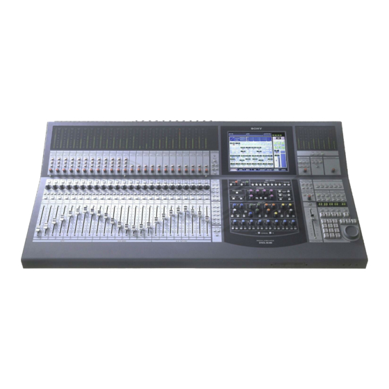
- Page 1 3-868-264-12 Digital Audio Mixer Operating Instructions Before operating the unit, please read this manual thoroughly and retain it for future reference. DMX-R100 1999 Sony Corporation...
- Page 2 Owner’s Record The model and serial numbers are located on the rear. Record the serial numbers in the spaces provided below. Refer to them whenever you call upon your Sony dealer regarding the product. Model No. DMX-R100 Serial No.______________ WARNING To prevent fire or shock hazard, do not expose the unit to rain or moisture.
-
Page 3: Table Of Contents
Table of Contents Chaper 1 Overview Chapter 2 Locations and Functions of Parts and Controls Chapter 3 Menu Overview ... 6 Connection Examples ... 7 Video Post Production ... 7 Music Production ... 8 Live Recording ... 9 Locations and Functions of Parts and Controls ... 10 Composition of the Front Panel ... - Page 4 MISC SETUP Window ... 84 KEYBOARD Window ... 86 For System Setup ... 87 Changing the Keyboard Type ... 87 Updating the DMX-R100 System ... 87 Memory Structure and Title ... 88 Structure of Snapshot and Automation Memory ... 88 About Titles ... 89 Basic Operation Procedure ...
- Page 5 Appendix Using the Automatic Isolate Function... 103 Using the Write Hold Mode ... 103 Punching In/Punching Out ... 104 Dialogues on the Window ... 107 Specifications ... 110 Input/Output Connectors ... 110 Audio Characteristics ... 112 Automation Function ... 113 Others ...
-
Page 6: Overview
Overview The DMX-R100 is a compact digital audio mixer for a post production house that creates digital media or digital broadcasting. High quality audio signal processing The unit allows you to select the sampling frequency to 44.1 kHz, 48 kHz, 88.2 kHz or 96 kHz. -
Page 7: Connection Examples
Connection Examples Video Post Production For the signal flow, see “Block Diagram” on page 121. Chaper 1 Overview... -
Page 8: Music Production
Connection Examples Music Production Chaper 1 Overview... -
Page 9: Live Recording
Live Recording Chaper 1 Overview... -
Page 10: Locations And Functions Of Parts And Controls
Locations and Functions of Parts and Controls Composition of the Front Panel For details, refer to pages indicated in parentheses. Channel Meter panel (11) Analog Head Amplifier panel (11) Channel Strip panel (12) Channel Fader Chapter 2 Locations and Functions of Parts and Controls Talk-Back panel (14) Display section (17) Assignment panel (16) -
Page 11: Analog Head Amplifier Panel
1 OVER (analog head amplifier peak) indicators Lights when the input level reaches the level where the analog head amplifier starts to clip. The clip level is about -6 dBFS. 2 SIGNAL (analog head amplifier signal) indicators Lights when the signal is input to the analog head amplifier. -
Page 12: Channel Strip Panel
Locations and Functions of Parts and Controls Channel Strip Panel Chapter 2 Locations and Functions of Parts and Controls... - Page 13 For example, the AUX 1 button is lit in the PANS section, this control operates as control for the send volume of AUX 1. For detailed information on the Assignment panel, see page Indication of the PAN control When the PAN controls are operating, the operation status is displayed on the control using the LEDs.
-
Page 14: Talk-Back Panel
Chapter 2 Locations and Functions of Parts and Controls... - Page 15 4 PGM button Press this button so that it lights, to route the talkback signal memorized on the OSC/TALK BACK window to the PGM output. 5 STUDIO button Press this button so that it lights, to route the talkback signal to the studio monitor output. 6 AUX button Press this button so that it lights, to route the talkback signal to the AUX bus memorized on the OSC/TALK...
-
Page 16: Assignment Panel
Locations and Functions of Parts and Controls Assignment Panel Chapter 2 Locations and Functions of Parts and Controls... -
Page 17: Parameter Setting Panel
5 MTR button Press this button so that it lights. The channel faders on the Channel strip panel function as the send-volume controls for the MTR bus. 6 TRIM button Press this button so that it lights. The channel faders on the Channel strip panel function as the trimming volume controls. - Page 18 Locations and Functions of Parts and Controls INPUT Section and BUS ASSIGN section INPUT section This section allows you to adjust the digital input signal. When the signal input is analog, you can adjust the converted digital signal. Buttons and controls in the INPUT section are only available for snapshot automation and not dynamic automation.
- Page 19 1 DYNAMICS IN button Press this button to make the dynamics section active. The settings on the DYNAMICS section are displayed on the DYNAMICS window (page 47). 2 Dynamics access section Selects the functions of dynamics parameter section ACCESS button for EXPAND/GATE: Press this button so that the corresponding DYNAMICS window opens.
- Page 20 Locations and Functions of Parts and Controls EQUALIZER section Chapter 2 Locations and Functions of Parts and Controls...
- Page 21 7 High-cut filter section FREQ control: Sets the cut-off frequency of the high- cut filter. IN button: Press this button to activate the high-cut filter. AUX SEND section and CHANNEL button 1 AUX SEND control 2 ON button 3 PRE button 4 CHANNEL buttons 1 AUX SEND control 2 ON button 3 PRE button...
-
Page 22: Master Panel
Locations and Functions of Parts and Controls Master Panel Master meter/studio monitor/solo mode sections SOLO button on the channel strip panel Headphones connector Buttons and controls in this section are not used for the automation functions. 1 Master meters Indicate the level of the signal selected by master meter button 2. - Page 23 4 SOLO MODE section Changes the function of the channel SOLO buttons. SOLO button: When this button is lit, the SOLO buttons on the channel strip panel function as ‘destructive solo’ buttons and cause all other channels to cut. For detailed information on how to set SOLO disabled, see “SOLO buttons”...
- Page 24 Locations and Functions of Parts and Controls Control room monitor section and PGM bus section SOURCES 2T-1 2T-2 CR MONITOR SETUP ACCESS PROGRAM Chapter 2 Locations and Functions of Parts and Controls...
-
Page 25: Automation Panel
Automation Panel SELECT MACHINE TC AUTOMATION SNAPSHOT SAFE HOURS MINUTES SECONDS FRAMES SNAPSHOT Chapter 2 Locations and Functions of Parts and Controls... - Page 26 Locations and Functions of Parts and Controls A button: Recalls automation data stored in the A buffer. B button: Recalls automation data stored in the B buffer. By using the A and B buttons, you can copy stored data between the A/B buffers as explained below. To copy the data stored in the A buffer to the B buffer Press and hold the A button for more than 2...
- Page 27 RECALL button: Press this button so that it lights, to recall the snapshot data or the cue currently displayed on the SNAPSHOT display window depending on the set condition of the TC LINK button. UNDO button: Press this button so that it lights, to clear the last snapshot operation.
-
Page 28: Elements Of The Rear Panel
Locations and Functions of Parts and Controls Elements of the Rear Panel Chapter 2 Locations and Functions of Parts and Controls... -
Page 29: Control Signal Connectors
Control Signal Connectors For connection examples, see page 7, for detailed information on connectors, see “Specifications” on page 110, and for signal flow, see “Block Diagram” on page 121. Control signal connectors (part 1) 1 FOOT SW connector (Phone jack) Connect the foot switch (not supplied) to control the remote automation functions. - Page 30 For expansion use in future. qa SERIAL connector (D-sub 9-pin) For expansion use in future. qs MONITOR connector (D-sub high density 15- pin) Used for connecting a standard computer’s monitor to repeat the DMX-R100 on board display. switch AUX SEND 2TR IN PUSH...
-
Page 31: Analog Signal Connectors
Analog Signal Connectors For connection examples, see page 7, for detailed information on connectors, see “Specifications” on page 110, and for signal flow, see “Block Diagram” on page 121. Analog Connectors (part 1) PUSH PUSH PUSH PUSH PUSH 1 IN A (analog input A) connectors 1 to 12 (XLR 3-pin) These connectors are enabled when the INPUT B button on the analog head amplifier panel is not... - Page 32 Locations and Functions of Parts and Controls Chapter 2 Locations and Functions of Parts and Controls...
-
Page 33: Digital Signal Connectors
Outputs the 2-channel digital PGM signal. 5 Slots 1 to 4 (slots for optional boards) Insert the optional boards here. For details of how to insert these boards, contact your Sony dealer. For detailed information on optional boards, see the next page. -
Page 34: Optional Boards
Locations and Functions of Parts and Controls Optional Boards DMBK-R101 8CH Analog Line In Board Inputs balanced analog signals (+4 dB standard). The input channels are selected on the AUDIO INPUT ROUTING screen. PUSH PUSH DMBK-R102 8CH Analog Line Out Board Outputs balanced analog signals (+4 dB standard). - Page 35 DMBK-R106 Interface Board for ADAT Connects external devices such as ADAT interface boards, or external devices such as tape recorders that have an ADAT interface. DMBK-R106 INTERFACE BOARD FOR ADAT DO 1-8 DI 1-8 DMBK-R107 INTERFACE BOARD FOR TDIF DI/O Chapter 2 Locations and Functions of Parts and Controls...
-
Page 36: Menu Structure
Menu Structure The window based operating menus of the DMX- R100 are organized in the following structure. For detailed information on each menu, refer to the pages indicated in parentheses. Menus related to automation (placed on the top bar on the display) •... -
Page 37: Basic Components And Functions Of The Windows
0 AUDIO button qa SNAPSHOT button Top bar 1 TITLE button “TITLE” is the term used in DMX-R100 for storing and recalling all the mixer’s automation and housekeeping functions for a project. The current title’s name is displayed in the TITLE button. - Page 38 Basic Components and Functions of the Windows • After executing KEEP, do not turn off the power while the cursor indication changes to an arrow showing that the data has been processed or while the LED on the floppy disk drive is on. In such a case, the unit is writing the data in the flash memory or is storing in the floppy disk.
- Page 39 WRITE buttons on the channel strips: Whenever you press the WRITE button, all of the controls that can be dynamically automated in the channel are READY’ed (i.e. are in READY status). Notes • The READY SETUP is automatically switched off when the timecode is run at PLAY speed.
- Page 40 Basic Components and Functions of the Windows 8 MASTER DROP IN button Under normal conditions (where there are no items subject to automation in WRITE mode), this button is displayed in dark red. If you touch the button while it is dark red, the button turns light red and controls in the automation READY status are ‘DROPed’...
-
Page 41: Operating The Touch Panel
Operating the Touch Panel Changing the channel “CH XX” which is displayed next to the window name indicates the number of the channel. To change the channel, press the ACCESS button on the corresponding channel strip. Example: To change the channels to be displayed from CH-1 to CH-48 Press the 25 to 48 button on the Assignment panel to switch the faders to channels 25 to 48. - Page 42 Basic Components and Functions of the Windows Writing data in the snapshot and automation data When READY SETUP button is light yellow All of the appropriate channel processing controls on the display can be switched into READY status by touching the button icons by or parameter numeric value window.
-
Page 43: Menu Windows
Menu Windows CHANNEL Window To open this window, touch the CHANNEL button on the bottom menu bar to open the menu, then select [CHANNEL]. The CHANNEL window displays the status of the By touching the item, the window corresponding to the item opens. By touching the display window, the item corresponding to the display window drops in or drops out, or switches between READY and SAFETY. -
Page 44: Input/Pan/Assign Window
Menu Windows INPUT/PAN/ASSIGN Window To open this window, touch the CHANNEL button on the bottom menu bar, then select “INPUT/PAN/ ASSIGN.” Or, when the CHANNEL window is displayed, touch any point of the INPUT/PAN/ ASSIGN display. 1 INPUT section Mode button Unit selection button 2 ASSIGN section 1 INPUT section... - Page 45 MS DECODE button: Inserts a middle/side decoder to convert the odd numbered chanel ( M - Mid- capsule) and even numbered channel (S - Side- capsule) to Left and Right. This is only active in STEREO mode. These signals are converted to right and left signals before the channel faders.
-
Page 46: Menu Equalizer/Filter Window
Menu Windows EQUALIZER/FILTER Window To open this window, touch the CHANNEL button on the bottom menu bar, then select “EQUALIZER/ FILTER.” Or, when the CHANNEL window is displayed, touch any point on the EQ/FIL display section. 1 Frequency characteristics graph 2 LF/LMF/HMF/HF equalizer section 3 LF/HF filter section... -
Page 47: Dynamics Window
DYNAMICS Window To open this window, touch the CHANNEL button on the bottom menu bar, then select “DYNAMICS”. Or when the CHANNEL window is displayed, touch any point of the DYNAMICS display. 1 Gain reduction meter 2 Dynamics characteristics 3 Parameter display section 4 Function selectors 5 DYNAMICS IN button 6 INSERTION POINT section... - Page 48 Menu Windows 4 Function selectors Switch the function to be displayed on the Parameter display section 3 between Expander/Gate and Compressor/Duck. EXPANDER/GATE tab: Touch this tab to select the Expander/Gate function. COMPRESSOR/DUCK tab: Touch this tab to select the Compressor/Duck function. 5 DYNAMICS IN button This puts the dynamics in the signal path.
-
Page 49: Aux Send Window
AUX SEND Window To open this window, touch the CHANNEL button on the bottom menu bar, then select “AUX SEND.” Or, when the CHANNEL window is displayed, touch any point on the AUX SEND display. This window allows you to display and control the settings for AUX SEND 1 to 8. -
Page 50: Audio Overview Window
Menu Windows AUDIO OVERVIEW Window To open this window, touch the AUDIO button on the bottom menu bar, then select “OVERVIEW”. This window allows you to see the settings performed on the unit at glance. To change channels from the page for CH 1 to CH 24 to the page for CH 25 to CH 48, touch the PAGE button on the window. -
Page 51: Audio Fader Window
AUDIO FADER Window To open this window, touch the AUDIO button on the bottom menu bar, then select “FADER.” This window allows you to see the fader levels of channels 1 to 48, the MTR busses, the AUX send busses and the AUX return busses. 1 Fader operation level 2 Automation level 1 Fader operation level... -
Page 52: Audio Fader Grouping Window
Menu Windows AUDIO FADER GROUPING Window To open this window, touch the AUDIO button on the bottom menu bar, then select “FADER GROUPING.” This window allows you to set the fader group and cut 1 Group selection area 2 Mode button 3 ON/OFF button 4 Channel buttons 1 Group selection area... - Page 53 To assign or remove the channel to or from the group, proceed as follows. Setting the GANG fader group Touch the desired group button. Example: To set GP 1 to the GANG mode: Touch the GROUP 1 button. Touch the mode button for the group selected in step 1 until GANG appears on the mode button.
- Page 54 Menu Windows Setting the CUT group You can set the CUT group with the same operation procedure as the ones for setting the GANG group except that you have to display CUT on the mode button in step 2. The cut group number is displayed on the lower part of the channel button.
-
Page 55: Audio Input Routing Window
AUDIO INPUT ROUTING Window To open this window, touch the AUDIO button on the bottom menu bar, then select “INPUT ROUTING.” This window allows you to assign the desired input signal to the desired channel. 1 Destination select buttons 2 V button 3 Source select button 2 v button 4 DEFAULT button... - Page 56 Menu Windows The display of the block list buttons corresponding to SLOT 1 to SLOT 4 depends on the board inserted. • When the DMBK-R101 is inserted: SLOTxADC1 to • When the DMBK-R102 is inserted: SLOTxDAC1 to • When the DMBK-R103 is inserted: SLOTxDIO1 to •...
-
Page 57: Audio Output Routing Window
AUDIO OUTPUT ROUTING Window To open this window, touch the AUDIO button on the bottom menu bar, then select “OUTPUT ROUTING”. This window allows you to assign the bus output signal to the desired output connector. 2 V button 1 Bus select button 2 v button 3 DEFAULT button 1 Bus select button... - Page 58 Menu Windows 4 Output connector select buttons SLOT 1 to 4, AUX SEND 1 to 8, PGM, MONI OUT Selects the output connector to which the bus block is routed. Each of SLOT 1 to SLOT 4 has 8 output connectors. 5 INSERTION buttons BUS buttons: Assigning an insert to an output bus is a 2 stage process.
-
Page 59: Monitor Window
MONITOR Window To open this window, perform one of the following: • Touch the AUDIO button on the bottom menu bar, then select “MONITOR.” • Press the SETUP button on the STUDIO LS section or the CR MONITOR section of the front panel. 1 STUDIO LS tab 2 CR MONITOR tab 3 MONITOR MODE buttons... - Page 60 Menu Windows 4 CUT ENABLE buttons When the CUT button on the CR MONITOR section is lit, you can cut the monitor signal by touching the desired CUT buttons, L, R, SURR L to SURR RS on the window. The SURROUND L, C, SW, R. LS and PS buttons are active only in the surround mode.
- Page 61 When DIS is displayed, the execution of the SOLO function is prohibited. Note In DMX-R100, the SOLO mode is the listening mode which cuts all other channels. So SOLO affects the monitor and other mixer outputs. The AFL and PFL are the non-destructive listening modes that do not affect the other mixer outputs.
-
Page 62: Osc/Talkback Window
Menu Windows OSC/TALKBACK Window To open this window, perform one of the following: • Touch the AUDIO button on the bottom menu bar, then select “OSC/TALKBACK”. • Press the SETUP button on the Talkback panel on the unit. 6 FREQUENCY SET buttons/GANG button/ display window 1 OSC (oscillator) tab... - Page 63 5 Output select buttons Touch the corresponding button to select the desired signal path for the oscillator signal. 6 FREQUENCY SET buttons/GANG button/ display window L SET/R SET buttons: Touch the SET button so that you can set the frequency of the L or R oscillator signal using the jog dial on the unit.
-
Page 64: Snapshot Window
Menu Windows SNAPSHOT Window To open this window, perform one of the following: • Touch the SNAPSHOT button on the bottom menu bar. • Press the SETUP button from among SNAPSHOT buttons on the Automation panel. 1 Page select button 2 Row select button 3 Snapshot list 2 Row select button... - Page 65 4 NEW button Touch this button to store the current mixer settings as a new snapshot data. The lowest unused number is used for the new snapshot and it is temporarily named “# + xx” (xx is the snapshot number). 5 STORE button Touch this button to store the current mixer setting to the snapshot data selected on the snapshot list 3.
-
Page 66: Cue Window
Menu Windows CUE Window To open this window, touch the CUE button on the bottom menu bar. This window allows you to control the cue function. For detailed information on cue operation, see page 96. TIMECODE button NUMBER button 1 Page select button 2 Row select button 3 LOCATE button 1 Page select button... - Page 67 Note Do not recall snapshots linked to continuous cues that have duration lower than 5 frames each other. Otherwise, only the snapshot linked with the last cue may be recalled. Automation data for duration of remaining cues may not be recalled and saved. 5 STORE button Touch this button to save a cue.
-
Page 68: Automation Window
Menu Windows AUTOMATION Window To open this window, touch the AUTOMATION button on the bottom menu bar. This window allows you to control aspects of the dynamic automation. 1 FREE MEMORY display 2 A/B BUFFER ROTATION section 3 AUTO RETURN TIME section 4 PUNCH IN/OUT section 1 FREE MEMORY display Displays the remaining amount of memory available... - Page 69 A Automation return mode button Touch this button to select the mode that returns to the previous data. BUTT: Returns to the previous data quickly after the DROP OUT. RAMP: Ramps back to the previous position after the DROP OUT. HOLD TO NEXT: Holds the position after the DROP OUT until the next automation move is replayed.
-
Page 70: Machine Control Window
To open this window, touch the MACHINE CONTROL button on the bottom menu bar. This window allows you to set up the mixer to control devices that use MIDI machine control (MMC), Sony 9-pin and timecode chase. Note There may be machines which cannot be controlled... - Page 71 Note The tape time may not be displayed depending on the machines connected. 5 LOCATE TIME display window and SET button Displays the time the machine locates when the LOCATE button 9 is touched. Touching the SET button allows you to enter the locate time using the ten key pad.
-
Page 72: Title Manager Window
This window allows you to create, store and load the mixer’s titles. 1 Title list In the DMX-R100, data related to a project (snapshot data, dynamic automation data, settings for sampling frequency, timecode mode, etc.) is called “Title.” There are two types of titles: •... - Page 73 2 SAVE button Touch this button to store the current title into the selected title on the list. Select the media where the current title is to be saved by the STORAGE MEDIA buttons 7 before attempting to save. Notes •...
- Page 74 Menu Windows 0 INFORMATION section The following information is displayed for the tile selected on the title list. You can enter the name and a memo in those rows. NAME row: Displays the name of the title. To enter the title name, touch the NAME row, and then enter the name using the keyboard connected to the unit or on the KEYBOARD window.
-
Page 75: Midi Window
MIDI Window To open this window, touch the SYSTEM button on the bottom menu bar, then select “MIDI” on the menu. This window allows you to perform the assignment of 1 MIDI CHANNEL section 2 CONTROL CHANGE section 3 PROGRAM CHANGE section 4 PC PORT MODE section 1 MIDI CHANNEL section RX channel display and channel increment and... -
Page 76: Sync/Time Code Window
Menu Windows SYNC/TIME CODE Window To open this window, touch the SYSTEM button on the bottom menu bar, then select “TIME CODE” on the menu. 1 SAMPLING FREQUENCY buttons 6 MEASURE/TEMPO section 5 TIME CODE READER section Synchronous signal section 1 SAMPLING FREQUENCY buttons Touch the button corresponding to the desired sampling frequency from 44.1 kHz, 48 kHz, 88.2 kHz... - Page 77 Touch this button to use the built-in word clock generator as the reference signal. When this button is selected, external digital audio equipment must be synchronized with the DMX-R100 that is the sync master. B VIDEO button The unit synchronizes using the video signal connected to the REF VIDEO connector on the unit.
- Page 78 Menu Windows B MAIN PLL status Displays the status of PLL which generates clock signals used internally by the unit. LOCK: Operating correctly. UNLOCK: Synchronization is lost. When the word clock signal is selected as the reference signal, check the setting of the terminated resistor or if the word clock selector is set correctly.
- Page 79 6 MEASURE/TEMPO section When the BARS button is lit on the timecode input section on the Automation panel, the beats and bars are calculated on the settings entered in this section. A MEASURE selector B TEMPO display window C OFFSET display window A MEASURE selector Selects the measures of a tune.
- Page 80 Menu Windows B PRESET button Touch this button to set ON. You can enter and display the preset time on the PRESET/GENERATE TIME display window. When the LOCAL mode is selected, touching START will generate timecode from the preset time. Enter the timecode using the keyboard connected to the unit or on the KEYBOARD window after touching the PRESET/GENERATE TIME display window.
-
Page 81: I/O Status Window
I/O STATUS Window To open this window, touch the SYSTEM button on the bottom menu bar, then select the I/O STATUS on the menu. This window allows you to check the performance of the digital audio input/output. 1 SLOT 1 to 4 section 2 DA 88 button 3 BUILD-IN DIGITAL I/O section 4 INFORMATION section... - Page 82 OFF. If this button is not turned on (lit in green) with a DA- 88 inserted into the slot, it is necessary to replace the ROM in the DMBK-R107 slot. Contact your Sony dealer. 3 BUILT-IN DIGITAL I/O section Displays the status of the signal of the built-in digital input/output connectors.
- Page 83 SLIP: Asynchronization causes interpolation or cropping of data. This results in noise or distortion. Check that the unit synchronizes with each unit correctly. However, when the sampling converter is effective on the DMBK-R104, there is no problem even if SLIP is displayed. •...
-
Page 84: Misc Setup Window
Menu Windows MISC SETUP Window To open this window, touch the SYSTEM button on the bottom menu bar, then select “MISC SETUP” on the menu. 1 DATE/TIME section 2 CHANNEL METERS section 1 DATE/TIME section Sets the built-in clock. YEAR MONTH HOUR (24-hour time display system) MINUTE... - Page 85 PST (post fader) button: Selects the signal of the point located before the pan of the input signal path. For AUX send, MTR bus and PGM, the signal after the master fader is selected. PEAK HOLD button Selects the method used to display the peak hold level of the input signals.
-
Page 86: Keyboard Window
Menu Windows KEYBOARD Window To open this window, touch the KEYBOARD button on the SNAPSHOT, CUT, TITLE MANAGER, MACHINE CONTROL, SYNC/TIMECODE or I/O STATUS window. 1 Entry display area 4 CAPS LOCK button 1 Entry display area Displays the characters entered. When the item is already named on the window opened before the KEYBOARD window opens, that name is displayed here. -
Page 87: For System Setup
The keyboard type indication on the bottom left of the window changes to the one selected. When you turn on the power of the DMX-R100, the starting-up window opens. After the starting-up window closed once, the bar indication [–] starts to blink on the left top of the LED window. -
Page 88: Memory Structure And Title
Memory Structure and Title Structure of Snapshot and Automation Memory Floppy disk Title config Saved into the floppy disk Snapshot Loaded from the floppy disk Automation Buffer A or B LOAD Title #10 Title #1 Title config Snapshot Automation Buffer A or B Built in flash memory Chapter 4 Operation Tips SAVE... -
Page 89: About Titles
About Titles Titles when turning on the power of the unit In operating the unit, data such as snapshots, dynamic automation data, sampling frequencies and timecode required for the mixing operation are stored in ‘Titles’. There are two types of titles: One is the “current title” automatically created in the flash memory, the other is the title stored as a file. - Page 90 Memory Structure and Title Default setting of the unit Item Setting Input routing • Connect AD 1 to 24 to CH-1 to CH-24. • When the DMBK-R105 is inserted in the option slot, connect each input channel of the DMBK-R105 to Insertion return 1 to 8. •...
-
Page 91: Basic Operation Procedure
Basic Operation Procedure Basic Mixer Operation Flow from Turning On to Monitoring Turning on the power Loading the existing title or creating a new title. Confirming/changing the sampling frequency and timecode Disabling automation operation Routing the input signal Routing the output signal To the next page The basic mixer operation is explained in the following operation flow chart. - Page 92 Basic Operation Procedure From the previous page Confirming/setting monitoring Setting the analog head amplifier Setting the channel Storing the channel settings as data Chapter 4 Operation Tips • Select the CR MONITOR tab on the MONITOR window (page 59) and confirm that CUT L/CUT R buttons are set to OFF.
- Page 93 Using the stereo signal When setting PAN of the channel to OFF Display “STEREO” on the MODE button by touching it on the INPUT/PAN/ASSIGN window (page 44). Set the PAN button to OFF on the INPUT/PAN ASSIGN window. Perform settings for the PROGRAM L/R buttons on the BUS ASSIGN section on the Parameter setting panel.
-
Page 94: Snapshot Automation Procedure
Basic Operation Procedure Snapshot Automation Procedure Storing/updating a snapshot data Chapter 4 Operation Tips The unit can memorize up to 99 control settings (snapshots). By linking the stored snapshot settings with the timecode, the snapshot automation operations are performed as explained below. Since the snapshot data is stored in the working memory when storing it by using the STORE button on the SNAPSHOT window, data stored in the work memory is cleared when restarting the unit or turning off the power... - Page 95 Recalling a snapshot data Changing the name of the snapshot data Deleting snapshot data To update the snapshot data: 1 Touch the number of the data that you want to update on the snapshot list on the window. At this time, you cannot select a not-registered snapshot. 2 Touch the STORE button on the window.
-
Page 96: Cue Operation Procedure
Basic Operation Procedure Cue Operation Procedure Initial cue Storing a cue point Chapter 4 Operation Tips Since the cue data is stored in the work memory when storing it by using the STORE button on the CUE window, data stored in the work memory is cleared when restarting the unit or turning off the power of the unit. - Page 97 Changing a timecode of a cue point Changing the snapshot data linked with the cue point Press the STORE button on the unit. A cue point with the specified cue number (02 in this example) is stored and automatically linked with the new snapshot data. To store the cue point on the CUE window Open the CUE window.
-
Page 98: Automation Procedure
Basic Operation Procedure Changing the name of the cue point Deleting a cue point Automation Procedure Chapter 4 Operation Tips Open the CUE window. Touch the CUE NAME display corresponding to the cue point that you want to change on the cue list. Enter a new name for the cue point on the KEYBOARD window or using the keyboard connected to the unit. - Page 99 Writing automation data at the first time (in ABS mode) Clear the current tile on the TITLE MANAGER window. Or clear the automation data by touching the MAKE STATIC EXECUTE button on the AUTOMATION window. All items subject to automation data are cleared. Even if the timecode advances and automation is set to the RUN status (where automation is being executed), data will not be recalled.
- Page 100 Basic Operation Procedure Updating automation data Fader operation and its results The following figures show the fader operation and the results of the fader operation. When operating the faders in ABS mode Manupulating the fader When operating the faders in trim mode Manupulating the fader Chapter 4 Operation Tips...
- Page 101 To update automation in ABS mode Set the tape recorder to play and set the desired automation items in READY status. The method used to set in READY status depends on faders, controls and buttons. When any processing control in a channel is in READY status, the channel’s WRITE button flashes.
- Page 102 Basic Operation Procedure ON/OFF of the CUT button: Press Release Cut data previsouly stored. Cut data currently stored. trigger trigger When shifting the stored Cut ON/OFF timing to an earlier time: When shifting the stored Cut ON/ OFF timing to a later time: Press the button before the change and release the button after timing.
-
Page 103: Using The Automatic Isolate Function
Using the Automatic Isolate Function Using the Write Hold Mode The automatic isolate function allows you to remove automation control from selected channel or function. Using this automatic isolate function, you can manually adjust the level, regardless of the stored automation data. Even if the automation item is set to the isolate function, the control will write automation data if dropped in. -
Page 104: Punching In/Punching Out
Basic Operation Procedure Punching In/Punching Out Punching in/punching out using the automation function Chapter 4 Operation Tips Drop in the item selected in step 4. Adjust the level. Repeat the adjustment by rewinding the tape as required. Set the SAFE button to OFF after adjusting the level to the proper one. Start the tape recorder. - Page 105 Performing punch in/punch out using the foot switch During the duration specified by the punch in/out function, the minimum level is stored as automation data for the corresponding fader. At the punch in point, the current fader level is stored. At the punch out point, the fader level of the previous data is stored.
- Page 106 Basic Operation Procedure Chapter 4 Operation Tips Locate the tape recorder at a point a little before the PUNCH IN time and start to play. Slide the faders up to the desired level. Set the foot switch to ON at the desired time. Stop the tape recorder at the proper timing.
-
Page 107: Dialogues On The Window
Dialogues on the Window In the following cases, a dialogue box appears on the window to confirm the operation and indicate the status of the unit. Selecting the [YES] or [CANCEL] button on the box gives the result shown in parenthesis. Cases When you touch the DELETE button on the SNAPSHOT window. - Page 108 Dialogues on the Window Cases The title files are corrupted. The storage space is insufficient to save the current title. Load error occurs. While saving a title, a write error occurs. The current title is corrupted when starting up the unit. The file of the title to be loaded is corrupted.
- Page 109 Cases When you execute to load or save the title while automation is being run: The tape recorder does not start operation even though 2 seconds have elapsed when MIDI controlling the tape recorder. When you copy data between the buffers A and B: When you execute MAKE STATIC function: When you try to change the initial cue while automation is being run:...
-
Page 110: Appendix
Specifications Input/Output Connectors Digital audio input/output Digital input connectors Connector Number of inputs AUX RET 5/6, 7/8 2TR IN 2 Digital output connectors Connector Number of outputs Number of channels AUX SEND 5/6, 7/8 2 Analog audio input/output Analog input connectors Number of Number channels... - Page 111 2, BNC type (loop through) (75 ) NTSC Color/ B & W XLR-3-32, Balanced/XLR-3-31, SMPTE/EBU Balanced DIN 5-pin, female MIDI standard D-sub 9-pin, female Sony 9-pin Mini DIN 8-pin, female Phone jack Make-point Mini DIN 6-pin, female PS/2 Mini DIN 6-pin, female PS/2...
-
Page 112: Audio Characteristics
Specifications Audio Characteristics Signal processing characteristics Characteristics Signal processing High frequency range Equalizer High-mid frequency range Low-mid frequency range Low frequency range High cut filter Filter Low cut filter Compressor/Ducking Dynamics Expander/Gate Oscillator Level meter Appendix Specification 32/40 bit floating point Frequency range : 622 Hz to 19.9 kHz (61 points) : 622 Hz to 39.8 kHz (73 points) -
Page 113: Automation Function
Another audio characteristics Characteristics Specifications Line input (LINE IN to PGM OUT) Frequency response Mic input (MIC IN to PGM OUT) Harmonic distortion Line input (LINE IN to PGM OUT) Mic input (MIC IN to PGM OUT) Noise level Mic input Mic input Crosstalk Between input and output channels... -
Page 114: Others
Others Power requirements DMX-R100 (UC): AC120 V, 60 Hz DMX-R100 (CE): AC 220 to 240 V -, 50/60 Hz Power consumption 200 W Peak inrush current (1) Power ON, current probe method: 50 A (240V) (2) Hot switching inrush current,... -
Page 115: Midi
MIDI MIDI Implementation Chart Function Transmitted Basic: At power on 1 to 16, OFF Channel: Assignable 1 to 16, OFF Mode: At power on Message Altered ********** Note Number True voice ********** Velocity: Note ON Note OFF After touch Keys Channels Pitch Bend Control change... -
Page 116: Control Change Table
MIDI Control Change Table Parameter Mode 1 Mode 2 change No. Function Function —— —— CH1 Fader CH1 Fader CH2 Fader CH2 Fader CH3 Fader CH3 Fader CH4 Fader CH4 Fader CH5 Fader CH5 Fader CH6 Fader CH6 Fader CH7 Fader CH7 Fader CH8 Fader CH8 Fader... - Page 117 Parameter Mode 1 Mode 2 change No. Function Function CH6 PAN CH7 CUT CH7 PAN CH8 CUT CH8 PAN CH9 CUT CH9 PAN CH10 CUT CH10 PAN CH11 CUT CH11 PAN CH12 CUT CH12 PAN CH13 CUT CH13 PAN CH14 CUT CH14 PAN CH15 CUT CH15 PAN...
-
Page 118: Index
Index Analog head amplifier Analog head amplifier panel ... 11 Setting operation flow ... 92 Analog signal Analog head amplifier panel ... 11 Analog signal connectors ... 31 Selecting the input connectors... 11 Assigning the bus ... 58 Assigning the input source ... 56 Automation Automation panel ... - Page 119 Memory Dynamic RAM ... 88 Flash memory ... 88 Memory structure ... 88 Menu Bottom menu bar ... 40 Menu structure ... 36 Menu windows AUDIO FADER window ... 51 AUDIO INPUT ROUTING window ... 55 AUDIO OUTPUT ROUTING window ... 57 AUDIO OVERVIEW window ...
- Page 120 Index Source AUDIO INPUT ROUTING window ... 55 Changing/selecting the source... 44 INPUT/PAN/ASSIGN window ... 44 Routing a source signal to a channel ... 55 Specifications Analog audio input/output ... 110 Audio characteristics ... 112 Automation function... 113 Control signal input/output ...
-
Page 121: Block Diagram
Block Diagram Fs = 44.1/48 kHz (1 fs) Appendix... - Page 122 Block Diagram Fs = 88.2/96 kHz (2 fs) Appendix...
- Page 124 Sony Corporation Printed in Japan...