Quick Links
opis
Supervised Power Supply Station
Installation guide
INTRODUCTION
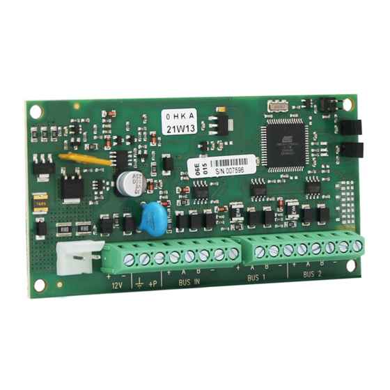
opis is a device that allows to extend the BUS on two additional branches. The power supply to the
branches it is provided by the same opis, protected by an 1.5 A auto restoring thermal fuse.
The device is fully supervised by the panel, with BUS status, power supply voltage and battery charge
information.
The opis power station is supplied already wired in the large metal cabinet (325 x 400 x 90 mm) with key
lock, equipped with a 2A / 220V fuse and a 3A switching power supply.
PCBA TECHNICAL DATA
•
Battery management: 18 Ah
•
Power supply: 14.2 Vdc
•
Consumption: 50 mA stand-by; 950 mA max
•
Operating temperature range: +5 +40 °C; 95% Humidity
•
Dimensions: 115x60x20 mm (PCBA)
•
Weight: 50 g
•
Maximum current available for external devices: 1400mA grade 2 - 200mA grade 3
code R30015.110en
ed. 01/2021
www.kseniasecurity.com

Related Manuals for Ksenia opis KSI2400000.300


Summary of Contents for Ksenia opis KSI2400000.300
- Page 1 opis Supervised Power Supply Station Installation guide INTRODUCTION opis is a device that allows to extend the BUS on two additional branches. The power supply to the branches it is provided by the same opis, protected by an 1.5 A auto restoring thermal fuse. The device is fully supervised by the panel, with BUS status, power supply voltage and battery charge information.
- Page 2 DESCRIPTION OF PCBA CONNECTIONS 14.2V LEGEND TEMINALS DESCRIPTION 1. Reserved Terminals + / - : Power supply input 14.2Vdc 2. Microswitch tamper 3. Signalation LEDs (M-B-S) : Protection ground see description in the : Output 12V power supply (1.5 A max) following table 4.
- Page 3 LEDs SIGNALATION (M - B - S) detail of PCBA: LEDs Power Supply status Steady: Correctly working Off: Power supply fault or missing AC network Battery Voltage status Steady: Correctly working Off: Fault or low battery level System Status Steady: Correctly working Flashing: Tamper and/or BUS IN connection fault POWER SUPPLY STATION TECHNICAL DATA •...
- Page 4 DESCRIPTION OF POWER SUPPLY STATION CONNECTIONS LEGEND 1. Metal bottom 2. Holes for passing cables 3. Bottom securing holes 4. opis PC board brackets 5. Trimmer to adjust the voltage at 14.2 6. Holes for cables fixing 7. Backup battery (Flammability class UL94-HB) 8.
-
Page 5: Installation
INSTALLATION Installing opis PCBA inside the metallic box (accessory code KSI7403130.010 or KSI7404130.010) with power station (adjust it at 14.2V): 1. Fix the metal cabinet to the wall using Ø 0.32 inch screws (options) 2. Place the opis PCBA in the metallic box with power supply charger 3.