ABB ACS580-01 +C135 Series Original Instructions Manual
Hide thumbs
Also See for ACS580-01 +C135 Series:
- Quick installation manual (2 pages) ,
- Quick installation manual (2 pages)

Related Manuals for ABB ACS580-01 +C135 Series


Summary of Contents for ABB ACS580-01 +C135 Series
- Page 1 — ABB DRIVES ACS580-01…, ACH580-01… and ACQ580-01… +C135 drives with flange mounting kit Supplement...
- Page 3 ACS580-01…, ACH580-01… and ACQ580-01… +C135 drives with flange mounting kit Supplement Table of contents 3. Mechanical installation – General 3AXD50000349821 Rev B Original instructions EFFECTIVE: 2022-06-17...
-
Page 5: Table Of Contents
Table of contents 5 Table of contents Introduction to the supplement Contents of this chapter ..................Applicability ....................... Target audience ......................Purpose of the supplement ..................Related documents ....................2 Hardware description Contents of this chapter ..................Product overview ...................... Layout and mounting position ................ - Page 6 6 Table of contents 5 Mechanical installation – Frames R4 and R5 Contents of this chapter ..................Unpacking and examining the delivery ..............Transport package contents ................Flange mounting kit package contents ............Mounting template ................Installation procedure ..................... Installing the drive on the mounting plate ..........6 Mechanical installation –...
-
Page 7: Introduction To The Supplement
Introduction to the supplement 7 Introduction to the supplement Contents of this chapter This chapter describes the supplement. Applicability This supplement is applicable to ACS580-01...+C135, ACH580-01...+C135 and ACQ580-01...+C135 drives with flange mounting kit. Target audience This supplement is intended for people who plan the installation and install the drive with the flange mounting kit. -
Page 8: Related Documents
8 Introduction to the supplement Related documents www.abb.com/drives/documents for all manuals on the Internet. The code below opens an online listing of the manuals applicable to the product: ACS580-01 manuals ACH580-01 manuals ACQ580-01 manuals... -
Page 9: Hardware Description
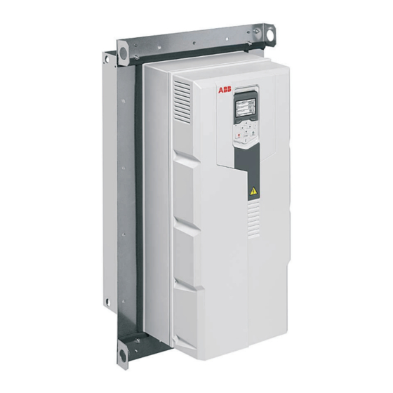
Hardware description 9 Hardware description Contents of this chapter This chapter describes the flange mounting kit. Product overview The flange mounting kit contains brackets for attaching the drive onto a mounting plate. The heatsink of the drive can be located in the cooling air channel, and the front part of the drive on the other side of the mounting plate. -
Page 10: Example: Tilted Position, Frames R1 To R3
10 Hardware description ■ Example: tilted position, frames R1 to R3 Mounting plate Side flange bracket Top flange bracket Bottom flange bracket Lifting hole Drive heatsink in the cooling air channel... -
Page 11: Example: Upright Position, Frames R4 To R9
Hardware description 11 ■ Example: upright position, frames R4 to R9 Hood (in the cooling air channel; required for UL Type 12) Top flange bracket Mounting plate Lifting hole Drive heatsink in the cooling air channel Side flange bracket Drive front side Bottom flange bracket Degree of protection The degree of protection of the back of the drive (heatsink) is always IP55 (UL... -
Page 12: Ordering Codes
12 Hardware description Ordering codes The flange mounting kit is a plus code option (+C135) or can be ordered separately with these ordering codes. Frame size Ordering code of flange mounting kit 3AXD50000105311 (IP21, UL Type 1) 3AXD50000105328 (IP21, UL Type 1) 3AXD50000105335 (IP21 and IP55, UL Type 1 and UL Type 12) 3AXD50000031460 (IP21, UL Type 1) 3AXD50000031461 (IP21, UL Type 1) -
Page 13: Mechanical Installation - General
Mechanical installation – General 13 Mechanical installation – General Contents of this chapter This chapter generally describes how to mechanically install the drive with the flange mounting kit. Safety instructions Obey the general safety instructions in the hardware manual and the task-specific instructions in this supplement. - Page 14 14 Mechanical installation – General • There is enough free space above and below the drive for cooling air flow, service and maintenance. There is enough free space in front of the drive for operation, service and maintenance. See section Free space requirements (page 15) When you install drives above one another, make sure that the outlet cooling...
-
Page 15: Free Space Requirements
Mechanical installation – General 15 Free space requirements The flange-mounted drives can be installed side by side. The free space requirements above and below the drives are shown below. For additional requirements, refer to sections Examining the installation site (page 13) Additional requirements for cabinet installations (page 16). -
Page 16: Additional Requirements For Cabinet Installations
16 Mechanical installation – General Additional requirements for cabinet installations Make sure that the cooling air gratings of the drive will not be covered. Make sure that the required cooling air flow is achieved. In a totally closed cabinet with no forced ventilation, a fan for circulating the air inside the cabinet may be needed. -
Page 17: Mechanical Installation - Frames R1 To R3
Mechanical installation – Frames R1 to R3 17 Mechanical installation – Frames R1 to R3 Contents of this chapter This chapter describes how to install drive frame sizes R1 to R3 with the flange mounting kit mechanically. Unpacking and examining the delivery ■... -
Page 18: Flange Mounting Kit Package Contents
18 Mechanical installation – Frames R1 to R3 ■ Flange mounting kit package contents The drawings below show the layout of the flange mounting kit packages. Examine that all items are present and there are no signs of damage. Straps Grounding plate (In frame R3 different) Side brackets Quick guide... -
Page 19: Mounting Template
Mechanical installation – Frames R1 to R3 19 Mounting template The flange mounting kit package includes a template in actual size for drilling the attaching holes and cutting the hole in the mounting plate. An example template is shown below. -
Page 20: Installation Procedure
20 Mechanical installation – Frames R1 to R3 Installation procedure For IP21 (UL Type 1): To remove the fan assembly, push the retaining clips. Lift the assembly up. 2. For IP21 (UL Type 1): Insert the sealing plug (a) to the hole. - Page 21 Mechanical installation – Frames R1 to R3 21 3. For IP21 (UL Type 1): Reinstall the fan assembly. 4. For IP21 (UL Type 1): To install the internal fan, see the hardware manual section Replacing the auxiliary cooling fan, IP55 (UL Type 12) frames R1 …R2 or Replacing the auxiliary cooling fan, IP55 (UL Type 12) frame R3.
- Page 22 22 Mechanical installation – Frames R1 to R3 6. Attach the U-brackets (b and c) to the back of the drive. (4.4 lbf·ft)
- Page 23 Mechanical installation – Frames R1 to R3 23 7. First attach the side brackets (d) to the U-brackets which were attached in step 5 using M6 nuts finger-tight. Then use the tightening brackets (e, M5×20 screws) to press the side brackets against the module. Tighten the side bracket nuts.
- Page 24 24 Mechanical installation – Frames R1 to R3 8. Attach the top (f) and bottom (g) brackets to the side brackets, first the inner sides (1) (the sides that touch the drive), then the outer sides (2). Remove the tightening bracket (e) from the top to enable replacement of the cooling fan. 8 ×...
-
Page 25: Optional Steps
Mechanical installation – Frames R1 to R3 25 ■ Optional steps Grounding plate For R1 and R2: If you wish to install the grounding plate, push it onto the alignment pins of the bottom bracket and attach it. (1.1 lbf·ft) (1.1 lbf·ft) - Page 26 26 Mechanical installation – Frames R1 to R3 For R3: To attach the grounding plate to the bottom plate use the cable entry plate screw (h). (1.1 lbf·ft)
-
Page 27: Power Cable Grounding Shelf
Mechanical installation – Frames R1 to R3 27 Power cable grounding shelf If you wish to install the power cable grounding shelf lower on the bottom bracket, first remove the cover and the cable entry plate. - Page 28 28 Mechanical installation – Frames R1 to R3 2. Detach the power cable shelf (screws i). Reinstall the screws (1.5 N·m/1.1 lbf·ft) to avoid moisture exchange through the empty holes! Attach the cable shelf to the bottom bracket with M4 nuts. Frame R3 is shown as an example. The cable shelf varies in different frame sizes.
-
Page 29: Installing The Drive On The Mounting Plate
Mechanical installation – Frames R1 to R3 29 ■ Installing the drive on the mounting plate See chapter Dimension drawings (page 55) for the dimensions of the flange and the required opening in the mounting plate. Attach the mounting template from the flange mounting kit package onto the mounting plate. - Page 30 30 Mechanical installation – Frames R1 to R3 2. To fulfill UL Type 12 requirements at the backside of the drive, attach the hood to the cooling channel. This is not required for IP55. R1…R2: 2 × M6 nuts 3 × M6 nuts 6 N·m (4.4 lbf·ft) Front Front...
- Page 31 Mechanical installation – Frames R1 to R3 31 3. Attach chains to the drive lifting holes and lift the drive with a lifting device onto the opening in the mounting plate. 4. Attach the bottom bracket with one screw. 5. Attach the top bracket with one screw. 6.
- Page 32 32 Mechanical installation – Frames R1 to R3...
-
Page 33: Mechanical Installation - Frames R4 And R5
Mechanical installation – Frames R4 and R5 33 Mechanical installation – Frames R4 and R5 Contents of this chapter This chapter describes how to install drive frame sizes R4 and R5 with the flange mounting kit mechanically. Unpacking and examining the delivery ■... -
Page 34: Flange Mounting Kit Package Contents
34 Mechanical installation – Frames R4 and R5 ■ Flange mounting kit package contents The drawings below show the layout of the flange mounting kit packages. Examine that all items are present and there are no signs of damage. Tightening brackets Bottom bracket Top and bottom U-brackets Side brackets... -
Page 35: Mounting Template
Mechanical installation – Frames R4 and R5 35 Mounting template The flange mounting kit package includes a template in actual size for drilling the attaching holes and cutting the hole in the mounting plate. An example template is shown below. -
Page 36: Installation Procedure
36 Mechanical installation – Frames R4 and R5 Installation procedure For R4, IP21 (UL Type 1): To remove the fan assembly, push the retaining clip with a flat screwdriver. Lift the assembly up. 2. For R4, IP21 (UL Type 1): Insert the sealing plug (a) to the hole. - Page 37 Mechanical installation – Frames R4 and R5 37 3. For R4, IP21 (UL Type 1): Reinstall the fan assembly 4. For R4, IP21 (UL Type 1): To install the internal fan for IP21 drives, first remove the covers. R4, IP21 (UL Type 1) R5, IP21, UL Type 1 R5, IP21, UL Type 1 To install the fan, see section Replacing the auxiliary cooling fan, IP55 (UL Type...
- Page 38 38 Mechanical installation – Frames R4 and R5 5. For IP 55 (UL Type 12): To remove the cover, remove the tightening screws with T20 Torx screwdriver (a). Lift the cover up (b) and lift it off (c). Recycle the cover according to ACS580-01, ACQ580-01 and ACH580-01 drives recycling instructions and environmental information (3AXD50000040612 [English]).
- Page 39 Mechanical installation – Frames R4 and R5 39 7. For R4, R5: Attach the side brackets (d) to the U-brackets using M6 nuts finger-tight. Then use the tightening brackets (e, 4 × M5×20 screws) to press the side brackets against the module.Tighten the side bracket nuts. (2.2 lbf·ft) (4.4 lbf·ft)
- Page 40 40 Mechanical installation – Frames R4 and R5 8. For R4, R5: Attach the top (f) and bottom (g) brackets to the side brackets, first the inner sides (1) (the sides that touch the drive), then the outer sides (2). 2 x M6 nut 6 N·m (4.4 lbf·ft) 8 ×...
- Page 41 Mechanical installation – Frames R4 and R5 41 9. For R4, R5: Remove the tightening bracket (e) from the front of the fan. 10. For R5: Attach the clamp plate. (4.4 lbf·ft)
-
Page 42: Installing The Drive On The Mounting Plate
42 Mechanical installation – Frames R4 and R5 ■ Installing the drive on the mounting plate See chapter Dimension drawings (page 55) for the dimensions of the flange and the required opening in the mounting plate. Attach the mounting template from the flange mounting kit package onto the mounting plate. - Page 43 Mechanical installation – Frames R4 and R5 43 2. To fulfill UL Type 12 requirements at the backside of the drive, attach the hood to the cooling channel. This is not required for IP55. (4.4 lbf·ft)
- Page 44 44 Mechanical installation – Frames R4 and R5 3. Attach the chains to the lifting holes of the flange and lift the drive with a lifting device onto the opening in the mounting plate. 4. Attach the bottom bracket with one screw. 5.
-
Page 45: Mechanical Installation - Frames R6 To R9
Mechanical installation – Frames R6 to R9 45 Mechanical installation – Frames R6 to R9 Contents of this chapter This chapter describes how to install drive frames sizes R6 to R9 with the flange mounting kit mechanically. Safety WARNING! For frame sizes R6 to R9: Use the lifting eyes of the drive when you lift the drive. -
Page 46: Unpacking And Examining The Delivery
46 Mechanical installation – Frames R6 to R9 Unpacking and examining the delivery ■ Transport package contents The flange mounting kit package is on the side of the drive package or sent separately. Examine that all items are present and there are no signs of damage. Read the data on the type designation label of the drive to make sure that the drive is of the correct type. -
Page 47: Flange Kit Contents
Mechanical installation – Frames R6 to R9 47 ■ Flange kit contents Quick guide Screw package: • M6 nut (11 pcs) Mounting template • M6×10 T30 (12 pcs) * • M6×25 T25 (R6…R8: 16 pcs, R9: 18 Top bracket pcs) Bottom bracket Side brackets Top cardboard cover... -
Page 48: Mounting Template
48 Mechanical installation – Frames R6 to R9 Mounting template The flange mounting kit package includes a template in actual size for drilling the attaching holes and cutting the hole in the mounting plate. An example template is shown below. -
Page 49: Installation Procedure
Mechanical installation – Frames R6 to R9 49 Installation procedure For IP 55 (UL Type 12): To remove the cover, remove the tightening screws with a T20 Torx screwdriver (a). Lift the cover up (b) and lift it off (c). Recycle the cover according to ACS580-01, ACQ580-01 and ACH580-01 drives recycling instructions and environmental information (3AXD50000040612... - Page 50 50 Mechanical installation – Frames R6 to R9 3. Attach the top and bottom brackets. (4.4 lbf·ft)
-
Page 51: Installing The Drive On The Mounting Plate
Mechanical installation – Frames R6 to R9 51 ■ Installing the drive on the mounting plate See chapter Dimension drawings (page 55) for the dimensions of the flange and the required opening in the mounting plate. Attach the mounting template from the flange mounting kit package onto the mounting plate. - Page 52 52 Mechanical installation – Frames R6 to R9 2. To fulfill UL Type 12 requirements at the backside of the drive, attach the hood to the cooling channel. This is not required for IP55. (4.4 lbf·ft)
- Page 53 Mechanical installation – Frames R6 to R9 53 3. Attach the chains to the lifting holes of the flange and lift the drive with a lifting device onto the opening in the mounting plate. 4. Attach the bottom bracket with one screw. 5.
-
Page 55: Dimension Drawings
Dimension drawings 55 Dimension drawings Contents of this chapter This chapter contains the dimension drawings of the flange mounting kits and required openings in the mounting plate. -
Page 56: Frame R1
56 Dimension drawings Frame R1... - Page 57 Dimension drawings 57 Hood is needed for UL Type 12 installation only.
-
Page 58: Attaching Points And Hole Dimensions
58 Dimension drawings ■ Attaching points and hole dimensions... -
Page 59: Frame R2
Dimension drawings 59 Frame R2... - Page 60 60 Dimension drawings Hood is needed for UL Type 12 installation only.
-
Page 61: Attaching Points And Hole Dimensions
Dimension drawings 61 ■ Attaching points and hole dimensions... -
Page 62: Frame R3
62 Dimension drawings Frame R3... - Page 63 Dimension drawings 63 Hood is needed for UL Type 12 installation only.
-
Page 64: Attaching Points And Hole Dimensions
64 Dimension drawings ■ Attaching points and hole dimensions... -
Page 65: Frame R4
Dimension drawings 65 Frame R4... - Page 66 66 Dimension drawings Hood is needed for UL Type 12 installation only.
-
Page 67: Attaching Points And Hole Dimensions
Dimension drawings 67 ■ Attaching points and hole dimensions... -
Page 68: Frame R5
68 Dimension drawings Frame R5... - Page 69 Dimension drawings 69 Hood is needed for UL Type 12 installation only.
-
Page 70: Attaching Points And Hole Dimensions
70 Dimension drawings ■ Attaching points and hole dimensions... -
Page 71: Frame R6
Dimension drawings 71 Frame R6... - Page 72 72 Dimension drawings Hood is needed for UL Type 12 installation only.
-
Page 73: Attaching Points And Hole Dimensions
Dimension drawings 73 ■ Attaching points and hole dimensions... -
Page 74: Frame R7
74 Dimension drawings Frame R7... - Page 75 Dimension drawings 75 Hood is needed for UL Type 12 installation only.
-
Page 76: Attaching Points And Hole Dimensions
76 Dimension drawings ■ Attaching points and hole dimensions... -
Page 77: Frame R8
Dimension drawings 77 Frame R8... - Page 78 78 Dimension drawings Hood is needed for UL Type 12 installation only.
-
Page 79: Attaching Points And Hole Dimensions
Dimension drawings 79 ■ Attaching points and hole dimensions... -
Page 80: Frame R9
80 Dimension drawings Frame R9... - Page 81 Dimension drawings 81 Hood is needed for UL Type 12 installation only.
-
Page 82: Attaching Points And Hole Dimensions
82 Dimension drawings ■ Attaching points and hole dimensions... -
Page 83: Further Information
Product and service inquiries Address any inquiries about the product to your local ABB representative, quoting the type designation and serial number of the unit in question. A listing of ABB sales, support and service contacts can be found by navigating to www.abb.com/searchchannels. - Page 84 3AXD50000349821 B © Copyright 2022 ABB. All rights reserved. Specifications subject to change without notice.