Table of Contents
Quick Links
Table of Contents

Related Manuals for Moog MAVIS


Summary of Contents for Moog MAVIS
- Page 1 MAVIS USER’S MANUAL...
- Page 3 “Everything has some consciousness, and we tap into that. It is about energy at its most basic level.” - Dr. Robert Moog -...
- Page 4 Important Safety Instructions WARNING: WHEN USING ELECTRIC PRODUCTS, THESE BASIC PRECAUTIONS SHOULD ALWAYS BE FOLLOWED. Read and follow all the instructions before using the product. Heed all warnings and keep these instructions for later reference. Do not use apparatus near water—for example, but not limited to, near a bathtub, washbowl, or kitchen sink;...
- Page 5 Mavis should be stored in temperatures above 32 degrees Fahrenheit (0 degrees Celsius) but never greater than 135 degrees Fahrenheit (57 degrees Celsius). Do not leave Mavis in a vehicle on a hot day with the windows closed. Temperatures in a vehicle can exceed 175 degress Fahrenheit (80 degrees Celsius).
-
Page 6: Table Of Contents
The Envelope Generator (EG) The Voltage Controlled Amplifier (VCA) The Keyboard The Utilities (UTL) The Patchbay Patchbay Module Functions Wave Folding The Mixer MULT Attenuator Sample + Hold Using Mavis as a Eurorack Module Calibration Signal Flow Specifications Warranty & Service Information... -
Page 7: Assembly Instructions
Assembly Instructions... - Page 8 This is called electrostatic discharge, and it can be harmful to electronic components. To protect the circuitry when you are assembling your Mavis, leave the circuit board in its protective anti-static sleeve until you are ready to install it. Also, take a moment to ground yourself by touching a metal surface or grounded object before you handle the circuit board.
- Page 9 ATTACH THE FEET The square self-adhesive Rubber Feet should be placed on the corresponding square areas on the bottom side of the Chassis. Remove the protective film from each foot, apply, and hold firmly for a few seconds. SECURE PCB TO FRONT PANEL Carefully remove the Printed Circuit Board (PCB) from the sleeve.
- Page 10 ATTACH THE LID Mavis includes a protective Lid that keeps dust and debris off of your instrument. Place the Lid on top of Mavis when not in use, while in transit, and for the next assembly step. APPLY THE SERIAL NUMBER Now that you’ve built your new instrument, it’s...
-
Page 11: Setup & Connections
NOTE: There is no power switch on your Mavis. Once connected to the power supply, the unit is On. Mavis is an analog instrument and should be allowed to warm up before use. In cases where it has been left in a cold car overnight, for example, it may take even longer for the oscillator tuning to stabilize. -
Page 12: About Mavis
This is the basis for the term Modular Synthesizer. The first Moog synthesizers were modular synthesizers. In this diagram of Mavis modules, the solid lines represent audio signals, and the dotted lines represent control signals. The definitions and functions of each module are described later in the "Panel Controls &... -
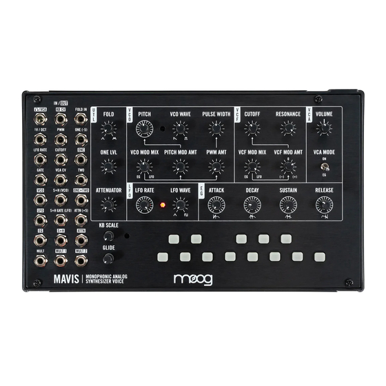
Page 13: Meet Mavis
Meet Mavis... -
Page 14: Default Settings
Now that your Mavis is assembled and fully functional, here are a couple of quick exercises that allow you to become more familiar with how it works. Be sure that Mavis is connected to an AC power source using the included adapter, and connect a set of headphones to /VCA output jack. -
Page 15: Listening To Wave Shapes
LISTENING TO THE FILTER Mavis is equipped with a low-pass audio filter to further shape the timbre of your sound. The CUTOFF knob sets the frequency of the filter. Simply put, sonic... -
Page 16: Applying Modulation
PULSE WIDTH knob and the CUTOFF knob noticeably affected the sound. In a voltage-controlled analog synthesizer such as Mavis, we can apply a modulation source (Control Voltage) to automatically change the value of these parameters. Mavis contains two hardwired modulation sources. -
Page 17: Patching Examples
Mavis is the first Moog instrument to ever feature a wave folder. The wave folder is not part of the Mavis signal chain by default, and must be patched in to use. -
Page 18: Mult
MULT The MULT is a simple module that allows you to route one signal to two different destinations. Continuing from the SAMPLE + HOLD example above, you may want to route the S+H effect to change the frequency of the VCO in addition to the filter cutoff. -
Page 19: One+Two Mixer
ONE input jack (R3; C3) and associated ONE LVL knob with a signal in the TWO input jack (R4; C3). One of the most powerful uses of this mixer is to turn Mavis into a two-oscillator synthesizer by using the LFO at audio rate. -
Page 20: Panel Controls & Functions
Panel Controls & Functions... -
Page 21: The Voltage Controlled Oscillator (Vco)
Sound begins with an object moving back and forth; this could be a guitar string, a clarinet reed, the vocal cords, or—in the case of a synthesizer—an Oscillator. Mavis uses a single Voltage Controlled Oscillator (VCO) to generate sound. The top row of knobs control Oscillator parameters related to pitch and timbre;... - Page 22 VCO WAVE (Oscillator Wave Shape) Each wave shape has its own particular timbre, based on its harmonic content. Mavis allows you to select a SAW wave, a PULSE wave, or any mix of these two waves using the VCO WAVE knob. Rotating this knob fully counterclockwise will create a Saw wave, and rotating this knob fully clockwise will create a Pulse wave.
- Page 23 PITCH MOD AMT (Pitch Modulation Amount) This knob determines the amount of modulation being applied to the PITCH parameter. The shape of this modulation is determined by the position of the VCO MOD MIX knob. Rotate the PITCH MOD AMT knob clockwise to increase the amount of modulation being applied to the PITCH parameter.
-
Page 24: The Voltage Controlled Filter (Vcf)
The top row of knobs controls the Filter parameters; the second row of knobs are used to apply modulation to the Cutoff frequency. NOTE: The Filter is of the classic 4-Pole Moog Ladder design, providing -24 dB of attenuation (per octave) to harmonic content above the Cutoff frequency. - Page 25 Cutoff and Resonance can be heard with more clarity. FILTER MODULATION PARAMETERS As with Oscillator Modulation, Mavis contains two modulation sources that can be applied to vary the Cutoff frequency of the Filter. The first is the LFO (Low Frequency Oscillator). This provides a repeating, cyclic change based on the current settings of the LFO RATE and LFO WAVE parameters.
-
Page 26: The Low Frequency Oscillator (Lfo)
LFO speed. TIP: The Mavis LFO has an upper frequency of around 550 Hz—well within the audio range. This ability allows the LFO to be used as an audio source, but also to create rich and unusual sounds when modulating the VCO PITCH or other parameters. - Page 27 LFO WAVE (LFO Wave Shape) The Mavis LFO creates two distinct wave shapes—triangle and square. This knob allows you to mix these two waves together to create a greater variety of modulation waves. Rotating the knob to the full clockwise position selects the square wave.
-
Page 28: The Envelope Generator (Eg)
The Envelope Generator (EG) The four stages of an Envelope Generator—Attack, Decay, Sustain, and Release—combine to create one continuous control voltage that changes over time. By default, the EG modulates the VCA, articulating the amplitude of your sound every time a key is pressed. Via the patchbay, this control voltage can also be used as a modulation source to control other parameters. - Page 29 ENVELOPE PARAMETERS TIP: In order to explore the EG controls, be sure the VCA MODE switch is set to EG. Press any key on the keyboard to trigger new envelopes as you explore different settings of these parameters. ATTACK (Attack Time) The ATTACK knob determines the amount of time required for the control signal to rise from zero to its maximum level once a key is pressed.
-
Page 30: The Voltage Controlled Amplifier (Vca)
VCA PARAMETERS VOLUME The output level of Mavis is affected by a number of factors—Sustain Level, Cutoff Frequency, etc. The /VCA output jack is used either for headphone monitoring or as an output to a recording interface, mixer, or to connect with other equipment. -
Page 31: The Keyboard
Mavis is equipped with a one-octave, C to C keyboard. The keyboard uses soft-touch buttons, as opposed to traditional keys, but the layout is the same. Mavis may be played directly from this onboard keyboard, or from an external keyboard, a sequencer, or a controller using the 1V/OCT input jack (R2;... - Page 32 KB SCALE (Keyboard Scaling) With the KB SCALE knob rotated to the full counterclockwise position, the difference between the low C on the keyboard and the high C on the keyboard will be one octave, as you would expect. This change is also equivalent to one volt, or one volt per octave in modular synthesis terminology.
-
Page 33: The Utilities (Utl)
The Utilities (UTL) There are a number of very powerful synthesis modules integrated into Mavis. While some of the features and functions reside under the hood and in the patchbay, this Utilities section brings several important controls to the surface. - Page 34 ONE LVL (Mixer Channel one Level) Mavis is home to a two-input/one-output utility mixer. The level of the signal connected to the ONE (-5) input jack (R2; C3) is controlled by the ONE LVL knob. This knob can then act as a balance between the signal connected to the ONE (-5) input jack and the TWO input jack (R4;...
-
Page 35: The Patchbay
The Patchbay... - Page 36 Eurorack synthesizers, as well as with other electronic music devices that rely on voltage control. Mavis comes equipped with a set of five patch cables to get you started. Should you need more, packs of 6” and 12” Moog patch cables are available for purchase from your authorized Moog dealer.
- Page 37 KB CV (Keyboard Control Voltage output) R1; C2 This output carries a voltage equivalent to the voltage of the key being pressed on the Mavis keyboard. This voltage is determined by the key pressed and the value of the KB SCALE knob.
- Page 38 ONE (Mixer Channel 1 output), R3; C3 This jack is the output for Channel 1 of the internal mixer. The level of this output is controlled by the ONE LVL knob in the Utilities section. For more information, refer to "The Mixer"...
- Page 39 GATE (External Gate input), R4; C1 The control signal received at this input will trigger the EG, and hold the EG at the Sustain level until the control signal falls to 0. CV INPUT: 0 OFF (OFF threshold 1.5 V); +5 V ON (ON threshold 3.5 V) VCA CV (Voltage Controlled Amplifier input), R4;...
- Page 40 S+H (Sample + Hold output) R7; C2 The output of the Sample + Hold generator is available via this output. For more information, refer to "Sample+Hold" (page 44). CV OUTPUT: -5 V to +5 V LFO (Low Frequency Oscillator output) R6; C1 This output carries the LFO signal, based on all the LFO parameter knobs and settings, as well as any patching, such as to the LFO RATE input.
- Page 41 MULT (Mult Jack input) R8; C1 This jack acts as the input to the Mult jacks. This signal connected to this input jack will be available at both of the MULT output jacks. This allows the same signal to be sent to two different destinations. For more information, refer to "MULT"...
-
Page 42: Patchbay Module Functions
Using the Wave Folder, this truncated peak is inverted and added to the crest of the wave as a series of folds. Mavis employs a circuit design that uses LEDs to carry out the triple-folding process. The Wave Folder will be applied to any signal connected to the FOLD IN input jack (R1;... -
Page 43: The Mixer
THE MIXER Mavis is home to a two-channel utility mixer. The level of the signal connected to the ONE (-5) input jack (R2; C3) is controlled by the ONE LVL knob. This knob can then act as a balance between the signal connected to the ONE (-5) input jack and the TWO input jack (R4;... -
Page 44: Attenuator
By default, Mavis uses the VCO as the sample source. When using the VCO as the Sample + Hold source, keep in mind that the saw wave will provide a much broader range of voltages to sample from than the square wave—as the saw... -
Page 45: Using Mavis As A Eurorack Module
Lift the Front Panel slowly to remove Mavis from its Chassis. Look at the back of Mavis. There is a 10-pin Eurorack power header on the left side of the back of the PCB near the top. Connect the 10-pin side of a 10-pin to 16-pin Eurorack ribbon power cable to the power header on Mavis, following the diagram printed on the PCB and orienting Pin 1 (-12 V)—the red stripe on the... -
Page 46: Calibration
Calibration... - Page 47 1mV error per octave) KEYBOARD CALIBRATION Make sure Mavis has been powered on for at least 15 minutes, and that it is in a place where the temperature will not change drastically while performing the calibration. Remove all patch cables from the patchbay.
-
Page 48: Signal Flow
Mavis Signal Flow PULSE SHAPING S+H IN S+H OUT CORE RESONANCE S+H GATE INPUT SELECT VOLUME TRIM 1V/OCT LINE TRIM CUTOFF - 5V DRONE GAIN/ FOLD AMT CUTOFF EXT AUDIO/ WAVEFOLDER IN ONE+TWO GATE EG CIRCUITS GLIDE ATTN EG OUT... -
Page 49: Specifications
Specifications SOUND SOURCE MODULATION SOURCES Output: ATTN: Attenuator Output VCO (Voltage Controlled Oscillator) LFO (Low Frequency Oscillator) Range: 8 Hz–16 kHz Controllers: Sample + Hold Controllers: RATE knob: Modulation Frequency (.1 Inputs: Hz–550 Hz) VCO WAVE knob: Variable mix from S+H IN (VCO): Sample Voltage Source Saw to Pulse LFO WAVE knob: Variable mix from... -
Page 50: Warranty & Service Information
The Warranty Period is one year from the date of purchase. If, in Moog’s determination, it has been more than five years since the product shipped from our factory, it will be at Moog’s discretion whether to honor the warranty without regard to the date of the purchase. - Page 51 Clean Mavis with a soft, dry cloth only—do not use solvents or abrasive detergents. Heed the safety warnings at the beginning of the manual. Do not drop the unit. AN IMPORTANT NOTE ABOUT SAFETY: There are no user serviceable parts in Mavis. Refer all servicing to qualified personnel only.
- Page 52 MOOG, MOOG (stylized with design), and the MOOG logo are trademarks of Moog Music, Inc. Registered in U.S. Patent and Trademark Office and elsewhere. MAVIS is a trademark of Moog Music, Inc. MAVIS is part of the WERKSTATT family of instruments. Mavis User Manual Version 1 For the most up-to-date user manual and firmware updates, go to www.moogmusic.com/mavis.
- Page 53 Moog Music Inc is an Employee-Owned Company Located in Asheville, NC, USA...