Table of Contents
Quick Links
TABLE OF CONTENTS
1 Specifications ----------------------------------------------------- 2
2 Location of Controls and Components ------------------- 3
3 Troubleshooting Guide ----------------------------------------- 5
4 Disassembly and Assembly Instructions ---------------- 6
4.1. Main body and the dust box separation-------------- 6
4.2. Motor removal ---------------------------------------------- 6
4.3. Air outlet cover unit removal ---------------------------- 8
4.4. Main switch (with fuse) removal ----------------------- 8
4.5. Fuse replacement ----------------------------------------- 9
4.6. Power cord replacement--------------------------------- 9
4.7. Indicator pipe unit removal ------------------------------ 9
4.8. Cloth bag unit removal ----------------------------------10
5 Wiring Connection Diagram ---------------------------------11
6 Schematic Diagram ---------------------------------------------11
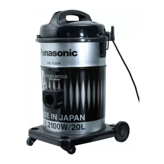
Model No.
Product Color : Black &Silver
Destination
PAGE
7 Exploded View and Replacement Parts List ----------- 12
7.1. EXPLODED VIEW (ATTACHMENTS) -------------- 12
7.2. PARTS LIST (ATTACHMENTS) ---------------------- 12
7.3. EXPLODED VIEW (BODY UNIT)-------------------- 13
7.4. PARTS LIST (BODY UNIT)---------------------------- 14
7.5. PACKING INSTRUCTIONS --------------------------- 15
7.6. PACKING LIST ------------------------------------------- 16
© Panasonic Corporation 2009 Unauthorized copy-
ing and distribution is a violation of law.
Order Number VCB0905004CE
Vacuum Cleaner
MC-YL699-S146
MC-YL699-S346
MC-YL699-S149
MC-YL699-S747
MC-YL699-S147
: 1.General --------------YL699-S146
2.Egypt -----------------YL699-S346
3.Iran --------------------YL699-S149
4.Saudi Arabia --------YL699-S747
Kuwait
5.UAE -------------------YL699-S147
PAGE
Table of Contents

Related Manuals for Panasonic MC-YL699-S146


Summary of Contents for Panasonic MC-YL699-S146
-
Page 1: Table Of Contents
4.6. Power cord replacement--------------------------------- 9 4.7. Indicator pipe unit removal ------------------------------ 9 4.8. Cloth bag unit removal ----------------------------------10 5 Wiring Connection Diagram ---------------------------------11 6 Schematic Diagram ---------------------------------------------11 © Panasonic Corporation 2009 Unauthorized copy- ing and distribution is a violation of law. -
Page 2: Specifications
1 Specifications Model No. MC-YL699 Motor power 2100W Dust capacity 20.0L Cord Length 8.0m Weight (With Attachments) 7.2kg METAL × 2 Extension Wand Blower Operation Floor Nozzle 2-Step Dimensions (WxLxH) 584mm x 340mm x 366mm Attachments Crevice Tool / Upholstery Nozzle Specifications are subject to change without notice for further improvement. -
Page 3: Location Of Controls And Components
2 Location of Controls and Components... -
Page 5: Troubleshooting Guide
3 Troubleshooting Guide CONDITION CHECKPOINT METHOD OF INSPECTION CAUSE / REMEDY Motor fails to rotate when it is Meltdown of fuse unit Check fuse continuity. Replace the main switch (with switched on (Visual and conduction check) fuse). *Check the motor at same time. -
Page 6: Disassembly And Assembly Instructions
4 Disassembly and Assembly Instructions Caution: 1. When disassembling, check the component fitting state and wirings. After repairing, always restore them to the original state. 2. Carefully handle the removed components, packing, etc. If they are damaged, then replace them with new ones. 3. -
Page 7
4. Remove the noise suppressor unit, the motor support When mounting, align form of the motor support rub- rubber (front), and the motor support rubber (rear) unit. ber (rear) unit with form of the body cover connection 3. Remove the lead wires by shifting the noise suppressor unit. -
Page 8: Air Outlet Cover Unit Removal
4.3. Air outlet cover unit removal 4.4. Main switch (with fuse) removal 1. Peel off the exhaust packing unit and remove the air out- let cover unit. 1. Remove the 2 screws mounting the handle. 2. Flip the body cover and remove the handle. * Locations of parts mounted to air outlet cover unit 3. -
Page 9: Fuse Replacement
4.5. Fuse replacement 2. Place the new power cord between the ribs of the body cover unit, and connect the wires with crimp contact. * Fuse is supplied by the main switch (with fuse) * Use the dedicated tool to crimp the crimp contact * Wrap the crimp contact with the protection tape B (glass tape). -
Page 10: Cloth Bag Unit Removal
4.8. Cloth bag unit removal 1. Remove the cloth bag unit from the expander. -
Page 11: Wiring Connection Diagram
5 Wiring Connection Diagram 6 Schematic Diagram... -
Page 12: Exploded View And Replacement Parts List
7 Exploded View and Replacement Parts List 7.1. EXPLODED VIEW (ATTACHMENTS) 7.2. PARTS LIST (ATTACHMENTS) Safety Ref.No Service Parts No. Part Name & Description Q'TY Remarks AMC84P-DD0V HOSE U AMC84P7X000J HOSE U UAE only AMC24P-0R0V HOSE SUPPORTER AMC98P4Y000J CURVED PIPE UNIT AMV09P99000J JOINT PIPE UNIT AMC99PDE000J... -
Page 13: Exploded View (Body Unit)
7.3. EXPLODED VIEW (BODY UNIT) -
Page 14: Parts List (Body Unit)
7.4. PARTS LIST (BODY UNIT) Safety Ref.No Service Parts No. Part Name & Description Q'TY Remarks AMV01B810K0J HANDLE (Carrying handle) AMV92A990K0J BODY COVER UNIT (Moter Housing) AMV85L81000J EXHAUST PACKING UNIT AMV98E8100CJ MAIN SWITCH With Fuse 12A AMC96L-DD0V BLOWER OUTLET UNIT With Cover Spring AMC51E-BY0 CORD BUSHING... -
Page 15: Packing Instructions
7.5. PACKING INSTRUCTIONS... -
Page 16: Packing List
7.6. PACKING LIST Safety Ref.No Service Parts No. Part Name & Description Q'TY Remarks AMV61Z990S0J Individual Carton AMV61Z990SXJ Individual Carton Egypt only AMC63Z-QN0 Bottom Plate AMC56Z-QN0 Cushion Bottom AMC70Z-QN0 Cushion B AMC69Z-QN0 Cushion A AMC98Z-QN0 Cushion Unit AMC68Z-QN0 Rear Protector AMC78Z-QN0 Supporter AMC72Z-QN0...