Table of Contents
Quick Links
GEN-LOCK PHASE
H
Before attempting to connect, operate or adjust this product, please
read these instructions completely.
Model No.
POWER
WIPE PATTERN
ON
WH1
WH2
WH3
OFF
S F 0
S F 1
S F 2
YLW
CYN
GRN
INCOM
MWR
I N T
F R Z
MGT
RED
BLE
I N V
LEVEL
SETTING
COLOR
SC
SC FINE
N
N / R
R
FRZ
A
5
1
2
3
4
FMEM
B
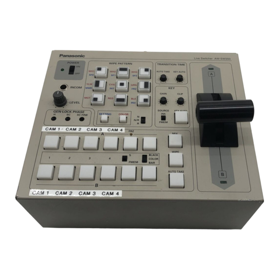
AW-SW350P
Live Switcher AW-SW350
TRANSITION TIME
AUTO TAKE
KEY AUTO
A
KEY
GAIN
CLIP
SOURCE
KEY AUTO
IN5
FMEM
MIX
WIPE
BLACK
COLOR
BAR
AUTO TAKE
B
Live Switcher
Table of Contents

Related Manuals for Panasonic AW-SW350P


Summary of Contents for Panasonic AW-SW350P
- Page 1 S F 0 INCOM LEVEL GEN-LOCK PHASE SC FINE Before attempting to connect, operate or adjust this product, please read these instructions completely. AW-SW350P Live Switcher AW-SW350 WIPE PATTERN TRANSITION TIME AUTO TAKE KEY AUTO S F 1 S F 2...
- Page 2 INTERFERENCE, USE THE RECOMMENDED ACCESSORIES ONLY. CAUTION: TO REDUCE THE RISK OF FIRE OR SHOCK HAZARD, REFER CHANGE OF SWITCH SETTING INSIDE THE UNIT TO QUALIFIED SERVICE PERSONNEL. Note: The rating plate (serial number plate is on the bottom of the unit.
-
Page 3: Table Of Contents
CONTENTS WARNING/CAUTION FOR SAFETY ... 5 PREFACE ... 6 FEATURES ... 6 PRECAUTIONS ... 7 MAJOR OPERATING CONTROLS AND THEIR FUNCTIONS ... 8 TOP (CONTROL PANEL) ... 8 REAR PANEL ... 15 IMAGE TRANSFER FUNCTION ... 20 FUNCTIONS ... 20 SPECIFICATIONS ... -
Page 4: Preface
• Care Switch power off and wipe the switcher with a dry cloth. If it is difficult to remove the dirt, dip a cloth into a diluted solution of kitchen detergent, squeeze it hard, and wipe the product carefully. -
Page 5: Major Operating Controls And Their Functions
Q Power Indicator [POWER] Lights (green) when power is supplied to DC Power Input Terminal L and Power Switch W set to the ON position, and goes out when Power Switch W is set to the OFF position. W Power Switch [POWER ON/OFF] Power is switched on and Power Indicator Q lights when this switch is set to the ON position, provided that power is supplied to DC Power Input Terminal L. - Page 6 Use the inversion mode when the input is black text on a white base. When the INV function is used with VIDEO IN 5 selected for the key source and with the FS switch in the OFF position, only the Video Input 5 signal will be set to the FS ON status.
- Page 7 B-Bus Input Selection Switches These are used to select the B-bus video signals. When a switch is pressed, it lights to indicate that the corresponding signal is selected. Depending on the operation mode, the switches may light with full or half brightness.
-
Page 8: Rear Panel
Auto Take will not work unless the lever is fully moved to A or B. i Fader Lever [A/B] This lever is used to switch the signal selected with A-Bus Input Selection Switch } to the signal selected with B-Bus Input Selection Switch q or vice versa by the wipe or mix effect. - Page 9 A-bus output D Genlock Input/BB Output Connector [GLIN/BBOUT] In compliance with the setting of the SETUP switch K, either the genlock input or BB output is selected. Genlock input: To apply genlock to the switcher, connect this signal to the signal generator...
- Page 10 In this case, the output is the same as the BBOUT F signal. EIntercom Switch [INCOM 3/4] The 3-wire or 4-wire type can be selected by setting the switch to the position appropriate to your system. (Set the switch to the 3-wire position if you are using the WV-RC700A or WV-RC550.) RBus Selector Switch [BUS A/B /F.F.]...
-
Page 11: Image Transfer Function
IMAGE TRANSFER FUNCTION The AW-SW350 Live Switcher comes with a function for transferring images from the host computer using the USB (Universal Serial Bus). The image data transferred from the host computer can be used as the key input signals or main input signals of the AW-SW350. When the image transfer function is to be used for the first time, the dedicated device driver and application program must be installed in the host computer. -
Page 12: Installing The Device Driver
(In this example, E: is the drive used.) Set the AW-SW350's Power Switch to ON, check that the Power Indicator has lighted, and connect one end of the A-B type USB cable to the USB port on the rear panel of the AW-SW350 and the other end to the USB port on the host computer. -
Page 13: Installing The Application Program
In order to confirm that the device driver has been installed successfully, it is recommended that you open the Device manager as shown in Fig.5, and check that “AW-SW USB Device:AW-SW350” is displayed. Fig.5 Device manager screen INSTALLING THE APPLICATION PROGRAM This section describes how to install the application program used with the USB image transfer program for the AW-SW350. -
Page 14: Operation Method
The installer program shown in Fig.7 now starts. Proceed with the installation by following the installer instructions. Fig.7 Application program installer start screen This completes the installation of the application program. Fig.8 Application program installation completion screen OPERATION METHOD This section describes how to operate the application program used with the USB image transfer program for the AW-SW350. - Page 15 When the target image appears in the image display area, specify the start or cutout position of the image. Which position is to be specified is determined by the number of pixels in the image file. • No. of pixels that can be displayed: 720 (H) x 487 (V) •...
- Page 16 Click the “RAM” radio button or “RAM+ROM” radio button to select the type of memory in which the data will be saved. (Fig.13) If “RAM” is selected, the image data is saved only in the frame memory and so it cannot be used after the AW-SW350 power has been turned off and back on again.
-
Page 17: Connections
For installation and connection, be sure to ask the store where you purchased the product. Before making any connection, switch off all the components of the system. Carefully read the manuals for the individual devices connected to the Live Switcher. -
Page 18: Connection To Personal Computer
VIDEO GLIN PGM OUT /BBOUT TALLY & INCOM AUTO Y / C IN Y / C SET UP TAKE AW-SW350 These switches operate whether the FS switch is in the ON or OFF position. Windows PC Connected with USB cable... -
Page 19: Example For The Connection With Pan/Tilt Heads And Control Panel
AW-RP505 The FS switch may be in either the ON or OFF position. If high picture quality is desired, set the FS switch to OFF and adjust each camera for horizontal and color phases. (Refer to the instruction manual for the camera.) -
Page 20: Rack Mounting
RACK MOUNTING RACK MOUNTING Do not mount the Live Switcher on a closed rack or bookshelf. (Otherwise, heat will build up inside and may cause a fire.) Keep the ventilation port open to secure good flow of air. Connecting plate Mounting screw Holes for... -
Page 21: Specifications/Standard Accessories
SPECIFICATIONS/STANDARD ACCESSORIES SPECIFICATIONS Power supply: 12 V DC (+10.8 ~ 16.0V) Power consumption: 16 W indicates safety information. Video Inputs Composite video signal: VBS: 1.0 V[p-p]/75 !5 (BNC connector, automatic termination) Y/C: 1.0 V[p-p]/75 0.286 V[p-p]/75 !5 (S connector) Video Outputs Composite video output: VBS: 1.0 V[p-p]/75 !2 (BNC connector) Y/C:... - Page 22 Memo...
- Page 23 DIVISION OF MATSUSHITA ELECTRIC CORPORATION OF AMERICA Executive Office: 3330 Cahuenga Blvd W., Los Angeles, CA 90068 (323) 436-3500 EASTERN ZONE: One Panasonic Way 4E-7, Secaucus, NJ 07094 (201) 348-7621 Southeast Region: 1225 Northbrook Parkway, Ste 1-160, Suwanee, GA 30024 (770) 338-6835 Central Region:...