Table of Contents
Quick Links
SERVICE MANUAL
Be sure to read this manual before servicing. To assure safety from fire, electric shock, injury, harmful radiation
and materials, various measures are provided in this Hitachi liquid crystal projector. Be sure to read cautionary
items described in the manual to maintain safety before servicing.
1. When replacing the lamp, avoid burns to your fingers. The lamp becomes very hot.
2. Never touch the lamp bulb with a finger or anything else. Never drop it or give it a shock. They may cause
bursting of the bulb.
3. This projector is provided with a high voltage circuit for the lamp. Do not touch the electric parts of power unit
(main), when turning on the projector.
4. Do not touch the exhaust fan, during operation.
5. The LCD module ass'y is likely to be damaged. If replacing the LCD module ass'y, do not hold the FPC of
the LCD module ass'y.
SPECIFICATIONS AND PARTS ARE SUBJECT TO CHANGE FOR IMPROVEMENT.
Liquid Crystal Projector
Caution
Service Warning
Contents
2
2
3
8
13
21
25
February 2000
SM0503
PJL1035 2
CPX940WB
CPX940E
26
27
29
47
48
50
Table of Contents

Related Manuals for Hitachi PJL1035 2


Summary of Contents for Hitachi PJL1035 2
-
Page 1: Table Of Contents
Be sure to read this manual before servicing. To assure safety from fire, electric shock, injury, harmful radiation and materials, various measures are provided in this Hitachi liquid crystal projector. Be sure to read cautionary items described in the manual to maintain safety before servicing. -
Page 2: Features
1. Features High brightness, High resolution Compact size, light weight for portability RGB output terminal RS232C Communication Mouse emulation Complies with VESA DDC1/2B specifications Auto-adjustment function 2. Specifications Drive system TFT active matrix Liquid crystal Panel size 0.9 inches panel Number of pixels 1024 (H) x 768 (V) Lamp... -
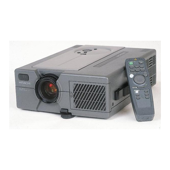
Page 3: Names Of Each Part
3. Names of Each Part Main Unit ON indicator This blinks in the standby mode and lights in the operation mode. STANDBY / ON button STANDBY/ON Power ON/OFF button. INPUT button OFF sets the unit in standby mode. INPUT To select the input source. Each time this button is pressed, the input MUTE source is changed in sequence as shown... - Page 4 Remote control sensor MAIN POWER switch Main power ON/OFF switch. : OFF : ON VIDEO input terminal (on video-equipped models only) S-VIDEO input terminal AC IN socket Mini DIN 4pin connector Connect the provided power cord. VIDEO input terminal RCA Jack AUDIO L/R input terminal RCA Jack S-VIDEO IN...
- Page 5 Remote Control Transmitter MUTE button STANDBY / ON button Silences the sound. (Cancels the mute when Power ON/OFF button. the unit is set in mute mode.) OFF sets the unit in standby mode. STANDBY/ON MUTE VOLUME button FREEZE Button Adjusts volume. The sound is loud or low Pressing this button displays a still picture FREEZE while pressing the "+"...
- Page 6 Function for Service Function Operation Press the RESET button of the projector or the TIMER Displayed the operating time of the lamp button of the remote control, for 3 seconds. Press the RESET button of the projector or the remote Reset the operating time of the lamp control MENU.
- Page 7 Message Table On-screen display The following messages are displayed on the screen. MESSAGE Action CHANGE THE LAMP The lamp has been in service for long. Replacement with a new lamp is AFTER REPLACING LAMP, recommended. The lamp will go off automatically when the lamp replacement RESET THE LAMP TIMER.
-
Page 8: Adjustment
4. Adjustment 4 - 1 Before adjusting. 4-1-1 ADJUSTMENT menu. The ADJUSTMENT menu is needed at all adjust- ADJUSTMENT menu ments. How to set up ADJUSTMENT menu follow these; a. Push the MENU button. PICTURE b. Keep the RESET button pushing for a several menu seconds while the PICTURE menu is displayed. - Page 9 PJL1035-2 4 - 2 P.O.filter adjustment. Before adjusting, input the 0.0Vp-p signal to check the 6. Slide the P.O.filter for GREEN on its base to find black image. If the image is not as dark as other set, out where a whole image is darkest by visual continue this procedure.
- Page 10 4 - 3 White balance adjustment Preparations for adjustment 4-3-1 Flicker adjustment. Refer to the attached drawing (Fig.4-4). 1. Use the XGA VESA(60) timing signal to input a 4. Use DAC_P - V.COM - G in the adjustment menu 0.35Vp-p R primary color signal for every other line. to adjust until flicker is minimum on a whole image.
- Page 11 4-3-3 The luminance adjustment. Use Minolta CL-100 at measurement and adjustment. 6. Return to procedure 4 to check the luminance is 1. Maximize CONTRAST and BRIGHT in the picture within the specification. If it is out of the menu. specification, repeat the procedure 4 - 5. 2.
- Page 12 4-3-4. Adjustment of the white balance. Use Minolta CL-100 at measurement and adjustment. b. Adjust DAC_P - BLACK POSI - R and DAC_P - 1. Low brightness white balance. BLACK POSI - B so that the chromaticity at the a. Input gray pattern at 0.21Vp-p with a timing signal center of the picture is of XGA VESA(60).
-
Page 13: Troubleshooting
SPEAKER I211 IS02 SPEAKER ETEP I201 ELCO EBLF EBAF EDS1 P701 P801 P901 PWB ass'y input EDI1 terminal video EVS1 I510 R244 EBOF EBAR PANEL TERMINAL < SIDE VIEW > < TOP VIEW > without upper case & I/O DECO PANEL without upper case... - Page 14 Power can not be turned on voltage input at pins of EDS1 on the PWB ass'y drive at standby mode? +12.5V Power unit (circuit) AC inlet Power switch FUSE +6.6V +16.5V Disconnect voltage ETEP for sensor from at R244 on the PWB ass'y drive.
- Page 15 Lamp does not light Check after trying to get on the projector Blinks Light Is the Lamp cover What is the state of Set the Lamp cover set correctly? LAMP indicator? Not light Change the lamp. Does Lamp light? Lamp Is the Lamp Set the Lamp again connection?
- Page 16 No picture is displayed although there is the RGB signal input. Check at operating mode picture displayed either selected RGB1 or RGB2 ? the 1/2 selected signal changed at pin of I211 on the PWB ass’y drive PWB ass’y drive "L"=RGB1, "H"=RGB2 ("H"=5V) PWB ass’y input terminal RGB...
- Page 17 No picture is displayed although there is the VIDEO signal input. Check at operating mode a voltage input at pin EVSI on the PWB ass’y input terminal VIDEO? Power unit PWB ass’y signal (circuit) Are the input signals output at pins EVSI on the PWB ass’y input terminal VIDEO?(*)
- Page 18 Picture is not displayed (both RGB and VIDEO input) Check at operating mode with RGB1 or 2 input voltage input at pins of EDS1 on the PWB ass'y drive? +6.6V +16.5V PWB ass'y signal PWB ass'y input terminal RGB Power unit (circuit) Are signal input at these pins of EDI1 on the...
- Page 19 No sound Check at operating mode No sound when VIDEO signal input (Sound is heard when RGB signal input) the audio signal output at pins of EVS1 on the PWB PWB ass'y input terminal VIDEO ass'y input terminal VIDEO? Audio L, Audio R PWB ass'y signal No sound both RGB and...
- Page 20 Signal Waveforms of P701, P801 and P901 (Input signal is VGA3) 3 ~ 14 VIDEO SIGNAL 1 PSIG (Uniformity Signal) 3.0 ~ 5.0V 4.5V 1.9V 7.8V 7.8V 1.9V 3.0 ~ 5.0V 4.5V 1H(17 s) 1H(17 s) 18, 19 HCK1,HCK2 17 HST 360 s 180ns 1H(17 s)
-
Page 21: Service Points
Therefore, regarding these parts, you can either replace part , LCD / Lens Prism Ass'y, or send the whole unit LCD / Lens Prism Ass'y back to Hitachi, where we will replace the malfunctioning part, recondition the device and send it back to you. In that case please contact our distributor. - Page 22 6 - 2 Service point of principal parts (1) Removing the UPPER CASE ASS'Y. 1. Remove 9 screws and remove the UPPER CASE ASS'Y. (2) Removing the PWB ASS'Y DRIVE. 1. Remove the UPPER CASE ASS'Y.(Refer to item 6-2(1)) 2. Release the lock of the connector housing and disconnect the FPC of the LCD module ass'y. 3.
- Page 23 6 - 3 About Lamp Replacement Light source lamp has a service life. The picture will become dark or color will be poor when the lamp is used for a long time. If usage of lamp is continued in such cases, it could cause a malfunction. Replace lamp with new one. As reference for replacement time, indicator will operate or message will be displayed when the power is turned on, as shown on page 6, 7.
- Page 24 4. Replace the lamp with new one and fix it using the same two screws. • Firmly tighten the lamp screws. Loose screws may cause bad Screw connection of the connector which in turn may result in malfunctioning. Lamp 5. Install the lamp cover and fix it using screws. •...
-
Page 25: Dust Cleaning
7. Dust Cleaning (1) Check dust condition 1. Show the white picture on the screen (whose size is 60") to check dust condition. 2. If dust condition is not good, should be clean the LCD module ass'y, the Multilenses and the Air filter. (2) Clean the LCD module ass'y (Don't remove the LCD ass'y) 1. -
Page 27: Wiring Diagram
Caution Be a wiring together in the top so that it may not be caught in the case because a cable is long. Caution PWB SIGNAL CNVID ESV1 EVS1 Fix the cable with an ESD1 adhesive tape so that VIDEO it may not be caught POWER UNIT in the rib. - Page 28 CNRGB Slider CNRGB PWB ASS'Y DRIVE EDI1 1. It turns it to lift the cable side of Slider (a white part). (Be careful because it breaks easily.) 2. After a CNRGB cable is POWER UNIT inserted, it turns it to (BALLAST) push both sides in both hands, and it closes...
-
Page 29: Basic Circuit Diagram
PWB ass'y COLOR... - Page 30 AUTO SETUP IC PWB ass'y DIGITAL...
- Page 31 PWB ass'y SIGNAL...
- Page 32 PWB ass'y VIDEO...
- Page 33 POWER UNIT (CIRCUIT) 1/2...
- Page 34 POWER UNIT (CIRCUIT) 2/2...
- Page 35 PWB ass'y DRIVE ( 1 / 9 )
- Page 36 PWB ass'y DRIVE ( 2 / 9 )
- Page 37 (DAGND BLOCK) PWB ass'y DRIVE ( 3 / 9 )
- Page 38 PWB ass'y DRIVE ( 4 / 9 )
- Page 39 PWB ass'y DRIVE ( 5 / 9 )
- Page 40 PWB ass'y DRIVE ( 6 / 9 )
- Page 41 PWB ass'y DRIVE ( 7 / 9 )
- Page 42 PWB ass'y DRIVE ( 8 / 9 )
- Page 43 PWB ass'y DRIVE ( 9 / 9 )
- Page 44 PWB ass'y RGB (1/3)
- Page 45 (female) (female) (female) PWB ass'y RGB (2/3)
- Page 46 (male) SERIAL MOUSE RS232C PWB ass'y RGB (3/3)
-
Page 47: Connector Connection Diagram
11. Connector Connection Diagram Fan(exhaust) Fan(intake) PWB ass’y digital (Lamp) (Power) EK01 EK01 EK01 EK01 EBAF EBLF EPOF EBOF 1 2 3 4 1 2 3 PWB ass’y TEMP 1 1 1 1 2 2 2 2 TEMPERATURE ETEP VCC(+12V) 1 1 1 1 PWB ass’y 2 2 2 2... -
Page 48: Disassembly Diagram
12. Disassembly Diagram 3X10 3X10 3X12 3X35 3X10 3X10 3X10 3X16 3X10 3X10 3X20 3X10 3X10 3X30 – 48–... - Page 49 3X12 – 49–...
-
Page 50: Replacement Parts List
THE UPDATED PARTS LIST FOR THIS MODEL IS AVAILABLE ON ESTA... - Page 51 Fax: +46 (0) 8 562 711 13 Tel: +39 02 38073415 Servizio Clienti Email: [email protected] Fax: +39 02 48786381/2 Email: [email protected] HITACHI EUROPE S.A.S HITACHI EUROPE LTD (Norway) AB Lyon Office STRANDVEIEN 18 B.P. 45, 69671 BRON CEDEX 1366 Lysaker FRANCE...