
Related Manuals for HP HPE ProLiant DL365 Gen10 Plus


Summary of Contents for HP HPE ProLiant DL365 Gen10 Plus
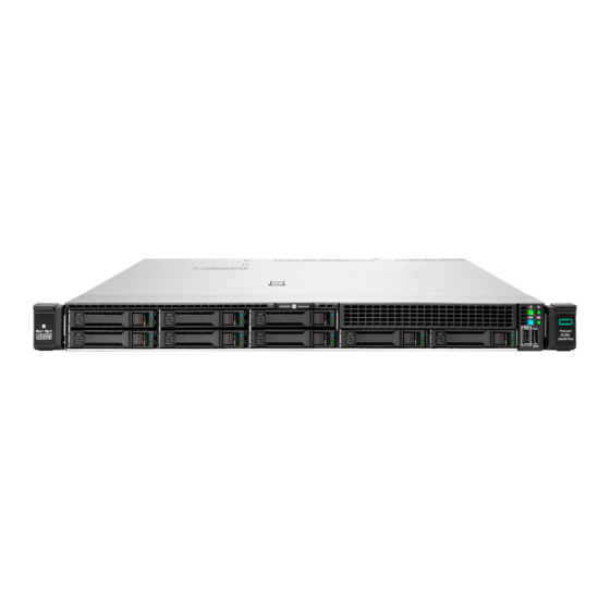
- Page 1 HPE ProLiant DL365 Gen10 Plus Server Maintenance and Service Guide HPE ProLiant DL365 Gen10 Plus Server Maintenance and Service Guide Part Number: 30-11CA689F-003 Published: October 2021 Edition: 3...
- Page 2 HPE ProLiant DL365 Gen10 Plus Server Maintenance and Service Guide HPE ProLiant DL365 Gen10 Plus Server Maintenance and Service Guide Abstract Abstract This document is for the person who installs, administers, and troubleshoots server and storage systems. Hewlett Packard Enterprise assumes you are qualified in the servicing of computer equipment and trained in recognizing hazards in products with hazardous energy levels.
-
Page 3: Table Of Contents
Table of contents Table of contents 1 Illustrated parts catalog 1.1 Mechanical components 1.1.1 Access panel spare part 1.1.2 PCIe riser cage spare part 1.1.3 PCIe riser blank spare parts 1.1.4 Server ear spare parts 1.1.5 Rack mounting hardware spare parts 1.1.6 DIMM guard spare part 1.1.7 Cable management arm spare parts 1.2 System components... - Page 4 3.3.3 Extend the server from the rack 3.3.4 Remove the server from the rack 3.3.5 Remove the access panel 3.3.6 Install the access panel 3.3.7 Release the cable management arm 3.4 Removing and replacing the bezel 3.5 Removing and replacing the cable management arm 3.6 Removing and replacing the easy install rails 3.7 Removing and replacing the ball bearing rails 3.8 Removing the hard drive blank...
- Page 5 5.1.1 Selecting the boot mode 5.1.2 Secure Boot 5.1.3 Launching the Embedded UEFI Shell 5.2 iLO Service Port 5.3 Intelligent Provisioning 5.4 HPE Insight Remote Support 5.5 HPE InfoSight for servers 5.6 USB support 5.6.1 External USB functionality 5.7 Smart Storage Administrator 6 Component identification 6.1 Front panel components 6.2 Front panel LEDs and buttons...
- Page 6 8.4 Hot-plug power supply calculations 9 Websites 10 Support and other resources 10.1 Accessing Hewlett Packard Enterprise Support 10.2 Accessing updates 10.3 Remote support 10.4 Warranty information 10.5 Regulatory information 10.6 Documentation feedback...
-
Page 7: Illustrated Parts Catalog
Illustrated parts catalog Illustrated parts catalog Illustrated parts catalog... -
Page 8: Mechanical Components
Mechanical components Mechanical components Hewlett Packard Enterprise continually improves and changes product parts. For complete and current supported parts information, see the Hewlett Packard Enterprise PartSurfer website Hewlett Packard Enterprise PartSurfer website . Item Item Description Description Access panel spare parts PCIe riser cage spare parts PCIe riser blank spare parts Server ear spare parts... -
Page 9: Access Panel Spare Part
Access panel spare part Access panel spare part Customer self repair: Mandatory Mandatory Description Description Spare part number Spare part number Access panel P42617-001 Access panel spare part... -
Page 10: Pcie Riser Cage Spare Part
PCIe riser cage spare part PCIe riser cage spare part Customer self repair: Optional Optional Description Description Spare part Spare part number number RISER, Tertiary, x16FH P31223-001 RISER, x16LP P31222-001 RISER, PCIe x16/x8/M.2 P28340-001 For primary riser board spares, see PCI riser board spare parts PCIe riser cage spare part... -
Page 11: Pcie Riser Blank Spare Parts
PCIe riser blank spare parts PCIe riser blank spare parts Customer self repair: Mandatory Mandatory Description Description Spare part Spare part number number PCIe riser blank, slotted 875537-001 PCIe riser blank spare parts... -
Page 12: Server Ear Spare Parts
Server ear spare parts Server ear spare parts Customer self repair: Mandatory Mandatory Table : Table : Description Description Spare part number Spare part number SFF left ear P38894-001 Right ear P38895-001 Server ear spare parts... -
Page 13: Rack Mounting Hardware Spare Parts
Rack mounting hardware spare parts Rack mounting hardware spare parts Customer self repair: Mandatory Mandatory Description Description Spare part number Spare part number 1U Easy Install SFF P38898-001 Rack mounting hardware spare parts... -
Page 14: Dimm Guard Spare Part
DIMM guard spare part DIMM guard spare part Customer self repair: Mandatory Mandatory Description Description Spare part number Spare part number 2U DIMM guard, left/right P24307-001 DIMM guard spare part... -
Page 15: Cable Management Arm Spare Parts
Cable management arm spare parts Cable management arm spare parts Customer self repair: Mandatory Mandatory Description Description Spare part Spare part number number 1U Cable Management Arm P38900-001 Cable management arm spare parts... -
Page 16: System Components
System components System components Hewlett Packard Enterprise continually improves and changes product parts. For complete and current supported parts information, see the Hewlett Packard Enterprise PartSurfer website Hewlett Packard Enterprise PartSurfer website . Item Item Description Description DIMM spare parts Processor spare parts Heatsink spare parts Smart array controller spare parts... -
Page 17: Dimm Spare Parts
DIMM spare parts DIMM spare parts Customer self repair: Mandatory Mandatory Description Description Spare part number Spare part number 3200 MT/s DIMMs 3200 MT/s DIMMs — 8 GB, single-rank x8 PC4-3200AA-R P20499-001 16 GB, dual-rank x4 PC4-3200AA-R P20500-001 16 GB, single-rank x8 PC4-3200AA-R P20501-001 32 GB, single-rank x4 PC4-3200AA-R P39381-001... -
Page 18: Processor Spare Parts
Processor spare parts Processor spare parts Processor spare parts... -
Page 19: Amd Epyc 7Xx2 Processor Spare Parts
AMD EPYC 7xx2 processor spare parts AMD EPYC 7xx2 processor spare parts Customer self repair: Optional Optional Description Description Spare part number Spare part number 3.20 GHz AMD EPYC 7262 processor, 8C, 155 W P17341-001 3.00 GHz AMD EPYC 7302 processor, 16C, 155 W P17339-001 2.35 GHz AMD EPYC 7452 processor, 32C, 155 W P17338-001... -
Page 20: Amd Epyc 7Xx3 Processor Spare Parts
AMD EPYC 7xx3 processor spare parts AMD EPYC 7xx3 processor spare parts Customer self repair: Optional Optional Description Description Spare part number Spare part number 3.70 GHz AMD EPYC 72F3 processor P39063-001 2.90 GHz AMD EPYC 7313 processor P39053-001 3.10 GHz AMD EPYC 7343 processor P39054-001 3.50 GHz AMD EPYC 73F3 processor P39064-001... -
Page 21: Heatsink Spare Parts
Heatsink spare parts Heatsink spare parts Customer self repair: Optional Optional Description Description Spare part number Spare part number Standard heatsink 1U P00248-001 High-performance heatsink 1U P24556-001 Heatsink spare parts... -
Page 22: Smart Array Controller Spare Parts
Smart Array controller spare parts Smart Array controller spare parts Customer self repair: Mandatory Mandatory Description Description Spare part Spare part number number HPE Smart Array E208i-a SR Gen10 Controller 836259-001 HPE Smart Array P408i-a SR Gen10 Controller 836260-001 HPE Smart Array E208i-p SR Gen10 Controller 836266-001 HPE Smart Array E208e-p SR Gen10 Controller 836267-001... -
Page 23: Pci Riser Board Spare Parts
PCI riser board spare parts PCI riser board spare parts Customer self repair: Optional Optional Description Description Spare part number Spare part number Primary PCIe riser P31228-001 x16/x8 M.2 riser P28340-001 Secondary riser x16 LP P31222-001 x16FH tertiary riser P31223-001 PCI riser board spare parts... -
Page 24: Network Adapter Spare Parts
Network adapter spare parts Network adapter spare parts Network adapter spare parts... -
Page 25: Ethernet Adapter Spare Parts
Ethernet adapter spare parts Ethernet adapter spare parts Customer self repair: Mandatory Mandatory Description Description Spare part number Spare part number HPE Ethernet 1Gb 4-port BaseT I350-T4 adapter P22200-001 HPE Ethernet 10Gb 2-port SFP+ QL41132 adapter P22199-001 HPE Ethernet 10Gb 4-port SFP+ QL41134 adapter P13346-001 HPE Ethernet 10Gb 2-port BaseT QL41132 adapter P11688-001... -
Page 26: Fibre Channel Host Bus Adapter Spare Parts
Fibre channel host bus adapter spare parts Fibre channel host bus adapter spare parts Customer self repair: Mandatory Mandatory Description Description Spare part number Spare part number HPE SN1600Q 32Gb 1p FC HBA 868140-001 HPE SN1600Q 32Gb 2p FC HBA 868141-001 HPE SN1600E 32Gb 1p FC HBA 869999-001... -
Page 27: Converged Network Adapter Spare Parts
Converged network adapter spare parts Converged network adapter spare parts Customer self repair: Mandatory Mandatory Description Description Spare part number Spare part number HPE CN1100R 2P Converged Network Adapter 706801-001 HPE StoreFabric CN1100R-T 10Gb Converged Network Adapter 872605-001 HPE StoreFabric CN1200E 10Gb Converged Network Adapter 767078-001 HPE StoreFabric CN1200E-T 10Gb Converged Network Adapter 827607-001 Converged network adapter spare parts... -
Page 28: Ocp 3.0 Adapter Spare Parts
OCP 3.0 adapter spare parts OCP 3.0 adapter spare parts Customer self repair: Optional Optional Description Description Spare part Spare part number number 1GbE 4-port BaseT I350-T4 OCP 3.0 adapter P14487-001 10GbE 2-port BT BCM 57416 OCP3 adapter P13640-001 OCP 3.0 adapter spare parts... -
Page 29: Infiniband Adapter Spare Parts
InfiniBand adapter spare parts InfiniBand adapter spare parts Customer self repair: Mandatory Mandatory Description Description Spare part number Spare part number HPE InfiniBand HDR100/Ethernet 1-port 940QSFP56 x16 P08356-001 Adapter HPE InfiniBand HDR100/Ethernet 100Gb 2-port 940QSFP56 x16 P08355-001 Adapter HPE InfiniBand HDR/Ethernet 200Gb 1-port 940QSFP56 x16 P08354-001 Adapter InfiniBand adapter spare parts... -
Page 30: System Board Spare Parts
System board spare parts System board spare parts Customer self repair: Optional Optional Description Description Spare part number Spare part number System board with sub-pan P40453-001 System board spare parts... -
Page 31: System Battery Spare Part
System battery spare part System battery spare part Customer self repair: Mandatory Mandatory Description Description Spare part number Spare part number System battery 319603-001 System battery spare part... -
Page 32: Server Options
Server options Server options Hewlett Packard Enterprise continually improves and changes product parts. For complete and current supported parts information, see the Hewlett Packard Enterprise PartSurfer website Hewlett Packard Enterprise PartSurfer website . Item Item Description Description Fan spare parts Power supply spare parts Battery and capacitor spare parts Hot-plug drive spare parts... -
Page 33: Fan Spare Parts
Fan spare parts Fan spare parts Customer self repair: Mandatory Mandatory Description Description Spare part number Spare part number Standard fan P31214-001 Max performance fan for Gen10 Plus P31213-001 Fan spare parts... -
Page 34: Power Supply Spare Parts
Power supply spare parts Power supply spare parts Customer self repair: Mandatory Mandatory Description Description Spare part Spare part number number 800W Flex-slot 48VDC 866728-001 500W Flex-slot Platinum 866729-001 800W Flex-slot Platinum 866730-001 800W Flex-slot High Efficiency Titanium 96% 866793-001 1600W Flex-slot Platinum 863373-001 1600W Flex-slot -48 VDC... -
Page 35: Battery And Capacitor Spare Parts
Battery and capacitor spare parts Battery and capacitor spare parts Customer self repair: Mandatory Mandatory Description Description Spare part Spare part number number HPE Smart Storage Hybrid Capacitor P07473-001 HPE Smart Storage Battery 878643-001 Battery and capacitor spare parts... -
Page 36: Hot-Plug Drive Spare Parts
Hot-plug drive spare parts Hot-plug drive spare parts Customer self repair: Mandatory Mandatory SFF drives SFF drives Description Description Spare part number Spare part number 300GB SAS 10k SFF SC HDD 785410-001 300GB SAS 10K SFF SC DS HDD 872735-001 300GB SAS 15K SFF SC HDD 759546-001 300GB SAS 15K SFF SC DS HDD... -
Page 37: Cable Kit Spare Parts
Cable kit spare parts Cable kit spare parts Customer self repair: Mandatory Mandatory Description Description Spare part number Spare part number PWR, SAS/SATA/H BRD, 8SFF P38905-001 SAS/SATA,2SFF BP,P816i-a,10P P38909-001 2SFF BP/NVMe/MLB to port8a/10P P42988-001 8SFF BP,S/S,P450/P850ar,10P P42987-001 2SFF U.3 BP, Pri NVMe, 10P P38920-001 2SFF U.3 BP, NVMe, 10P P38924-001... -
Page 38: Thermal Grease Spare Part
Thermal grease spare part Thermal grease spare part Customer self repair: Mandatory Mandatory Description Description Spare part number Spare part number 2.0g thermal grease (1g per processor) 777298-001 Thermal grease spare part... -
Page 39: Customer Self Repair
Customer self repair Customer self repair Hewlett Packard Enterprise products are designed with many Customer Self Repair (CSR) parts to minimize repair time and allow for greater flexibility in performing defective parts replacement. If during the diagnosis period Hewlett Packard Enterprise (or Hewlett Packard Enterprise service providers or service partners) identifies that the repair can be accomplished by the use of a CSR part, Hewlett Packard Enterprise will ship that part directly to you for replacement. - Page 40 remplacer ces pièces, les coûts de déplacement et main d'œuvre du service vous seront facturés. Riparazione da parte del cliente Riparazione da parte del cliente Per abbreviare i tempi di riparazione e garantire una maggiore flessibilità nella sostituzione di parti difettose, i prodotti Hewlett Packard Enterprise sono realizzati con numerosi componenti che possono essere riparati direttamente dal cliente (CSR, Customer Self Repair).
- Page 41 Ihre Hewlett Packard Enterprise Garantie umfasst möglicherweise einen Parts-only Warranty Service (Garantieservice ausschließlich für Teile). Gemäß den Bestimmungen des Parts-only Warranty Service stellt Hewlett Packard Enterprise Ersatzteile kostenlos zur Verfügung. Für den Parts-only Warranty Service ist das CSR-Verfahren zwingend vorgegeben. Wenn Sie den Austausch dieser Teile von Hewlett Packard Enterprise vornehmen lassen, werden Ihnen die Anfahrt- und Arbeitskosten für diesen Service berechnet.
- Page 42 Packard Enterprise moet worden geretourneerd. Als het defecte onderdeel aan Hewlett Packard Enterprise moet worden teruggezonden, moet u het defecte onderdeel binnen een bepaalde periode, gewoonlijk vijf (5) werkdagen, retourneren aan Hewlett Packard Enterprise. Het defecte onderdeel moet met de bijbehorende documentatie worden geretourneerd in het meegeleverde verpakkingsmateriaal.
- Page 43 Customer self repair...
- Page 44 Customer self repair...
- Page 45 Customer self repair...
- Page 46 Customer self repair...
-
Page 47: Removal And Replacement Procedures
Removal and replacement procedures Removal and replacement procedures Removal and replacement procedures... -
Page 48: Required Tools
Required tools Required tools The following tools might be required to perform some procedures: T-10/T-15/T-30 Torx screwdriver HPE Insight Diagnostics software Required tools... -
Page 49: Safety Considerations
Safety considerations Safety considerations Before performing service procedures, review all the safety information. Safety considerations... -
Page 50: Electrostatic Discharge
Electrostatic discharge Electrostatic discharge Be aware of the precautions you must follow when setting up the system or handling components. A discharge of static electricity from a finger or other conductor may damage system boards or other static-sensitive devices. This type of damage may reduce the life expectancy of the system or component. -
Page 51: Server Warnings And Cautions
Server warnings and cautions Server warnings and cautions WARNING: WARNING: This server is heavy. To reduce the risk of personal injury or damage to the equipment: Observe local occupational health and safety requirements and guidelines for manual material handling. Get help to lift and stabilize the product during installation or removal, especially when the product is not fastened to the rails. -
Page 52: Rack Warnings
Rack warnings Rack warnings WARNING: To reduce the risk of personal injury or damage to the equipment, be sure that: WARNING: The leveling jacks are extended to the floor. The full weight of the rack rests on the leveling jacks. The stabilizing feet are attached to the rack if it is a single-rack installation. -
Page 53: Preparation Procedures
Preparation procedures Preparation procedures To access some components and perform certain service procedures, you must perform one or more of the following procedures: Extend the server from the rack . If you are performing service procedures in a Hewlett Packard Enterprise, Compaq branded, Telco, or third-party rack cabinet, you can use the locking feature of the rack rails to support the server and gain access to internal components. -
Page 54: Power Up The Server
Power up the server Power up the server To power up the server, use one of the following methods: Press the Power On/Standby button. Use the virtual power button through iLO. Power up the server... -
Page 55: Power Down The Server
Power down the server Power down the server Before powering down the server for any upgrade or maintenance procedures, perform a backup of critical server data and programs. IMPORTANT: IMPORTANT: When the server is in standby mode, auxiliary power is still being provided to the system. To power down the server, use one of the following methods: Press and release the Power On/Standby button. -
Page 56: Extend The Server From The Rack
Extend the server from the rack Extend the server from the rack NOTE: NOTE: If the cable management arm option is installed, you can extend the server without powering down the server or disconnecting peripheral cables and power cords. These steps are only necessary with the standard cable management solution. -
Page 57: Remove The Server From The Rack
Remove the server from the rack Remove the server from the rack To remove the server from a Hewlett Packard Enterprise, Compaq-branded, Telco, or third-party rack: Procedure Procedure 1. Power down the server. 2. Extend the server from the rack . 3. -
Page 58: Remove The Access Panel
Remove the access panel Remove the access panel WARNING: To reduce the risk of personal injury from hot surfaces, allow the drives and the WARNING: internal system components to cool before touching them. CAUTION: Do not operate the server for long periods with the access panel open or removed. Operating the server in CAUTION: this manner results in improper airflow and improper cooling that can lead to thermal damage. -
Page 59: Install The Access Panel
Install the access panel Install the access panel Procedure Procedure 1. Place the access panel on top of the server with the latch open. Allow the panel to extend past the rear of the server approximately 1.25 cm (0.5 in). 2. -
Page 60: Release The Cable Management Arm
Release the cable management arm Release the cable management arm Release the cable management arm and then swing the arm away from the rack. Release the cable management arm... -
Page 61: Removing And Replacing The Bezel
Removing and replacing the bezel Removing and replacing the bezel Removing and replacing the bezel... -
Page 62: Removing And Replacing The Cable Management Arm
Removing and replacing the cable management arm Removing and replacing the cable management arm CAUTION: Support the CMA during the removal/replacement procedure. Do not allow the CMA to hang by its own CAUTION: weight during the procedure. Procedure Procedure 1. Extend the server from the rack . 2. - Page 63 To replace the component, reverse the removal procedure. Removing and replacing the cable management arm...
-
Page 64: Removing And Replacing The Easy Install Rails
Removing and replacing the easy install rails Removing and replacing the easy install rails WARNING: WARNING: To reduce the risk of personal injury or damage to the equipment, you must adequately support the enclosure during installation and removal. Prerequisites Prerequisites Before you begin, be sure that you have appropriate screwdriver for the screws in the rack. - Page 65 To replace the component, reverse the removal procedure. Removing and replacing the easy install rails...
-
Page 66: Removing And Replacing The Ball Bearing Rails
Removing and replacing the ball bearing rails Removing and replacing the ball bearing rails WARNING: WARNING: To reduce the risk of personal injury or damage to the equipment, you must adequately support the enclosure during installation and removal. Prerequisites Prerequisites Before you begin, be sure that you have the following items: Appropriate screwdriver for the screws in the rack. - Page 67 7. Secure the cables. Removing and replacing the ball bearing rails...
- Page 68 To replace the component, reverse the removal procedure. Removing and replacing the ball bearing rails...
-
Page 69: Removing The Hard Drive Blank
Removing the hard drive blank Removing the hard drive blank Remove the component as indicated. Removing the hard drive blank... -
Page 70: Removing And Replacing A Hot-Plug Sas, Sata Or Nvme Drive
Removing and replacing a hot-plug SAS, SATA or NVMe drive Removing and replacing a hot-plug SAS, SATA or NVMe drive CAUTION: To prevent improper cooling and thermal damage, do not operate the server unless all bays are populated CAUTION: with either a component or a blank. Prerequisites Prerequisites Determine the status of the drive from drive LED definition . -
Page 71: Removing And Replacing An M.2 Ssd
Removing and replacing an M.2 SSD Removing and replacing an M.2 SSD This procedure is for drives on the system board, riser, or expansion card. Do not use this procedure on uFF drives. Procedure Procedure 1. Power down the server. 2. -
Page 72: Removing And Replacing A Power Supply Blank
Removing and replacing a power supply blank Removing and replacing a power supply blank WARNING: To reduce the risk of personal injury from hot surfaces, allow the power supply or WARNING: power supply blank to cool before touching it. CAUTION: To prevent improper cooling and thermal damage, do not operate the server unless all bays are populated CAUTION: with either a component or a blank. -
Page 73: Removing And Replacing A Hot-Plug Ac Power Supply
Removing and replacing a hot-plug AC power supply Removing and replacing a hot-plug AC power supply WARNING: WARNING: To reduce the risk of electric shock or damage to the equipment: Do not disable the power cord grounding plug. The grounding plug is an important safety feature. - Page 74 4. Disconnect the power cord from the power supply. 5. Remove the power supply. Removing and replacing a hot-plug AC power supply...
- Page 75 To replace the component, reverse the removal procedure. Removing and replacing a hot-plug AC power supply...
- Page 76 Removing and replacing the HPE Removing and replacing the HPE 800 W Flex Slot -48 VDC hot-plug power supply 800 W Flex Slot -48 VDC hot-plug power supply The DC power supply option kits do not ship with a Power Supply DC cable Kit and may not include a Power Supply Cable Lug kit. The optional DC Cable kit or the optional DC Cable Lug Kit may be purchased directly from Hewlett Packard Enterprise or an authorized HPE reseller.
-
Page 77: Removing And Replacing The Hpe 800 W Flex Slot -48 Vdc Hot-Plug Power Supply
5. Detach the ground (earthed) cable from the power supply. 6. Remove the terminal block connector from the power supply. Removing and replacing the HPE 800 W Flex Slot -48 VDC hot-plug power supply... - Page 78 To replace the component, reverse the removal procedure. Removing and replacing the HPE 800 W Flex Slot -48 VDC hot-plug power supply...
-
Page 79: Removing And Replacing A Fan
Removing and replacing a fan Removing and replacing a fan CAUTION: Do not operate the server for long periods with the access panel open or removed. Operating the server in CAUTION: this manner results in improper airflow and improper cooling that can lead to thermal damage. IMPORTANT: For optimum cooling, install fans in all primary fan locations. -
Page 80: Removing And Replacing A Fan Blank
Removing and replacing a fan blank Removing and replacing a fan blank CAUTION: Do not operate the server for long periods with the access panel open or removed. Operating the server in CAUTION: this manner results in improper airflow and improper cooling that can lead to thermal damage. IMPORTANT: For optimum cooling, install fans in all primary fan locations. -
Page 81: Removing And Replacing A Pcie Blank
Removing and replacing a PCIe blank Removing and replacing a PCIe blank CAUTION: To prevent damage to the server or expansion boards, power down the server and remove all AC power CAUTION: cords before removing or installing the PCI riser cage. Procedure Procedure 1. - Page 82 To remove blanks from the secondary riser: a. Lift the rear wall latch. Half-height b. Remove the riser blank. Removing and replacing a PCIe blank...
- Page 83 Full-height To replace the component, reverse the removal procedure. Removing and replacing a PCIe blank...
-
Page 84: Removing And Replacing A Riser Cage
Removing and replacing a riser cage Removing and replacing a riser cage CAUTION: To prevent damage to the server or expansion boards, power down the server and remove all AC power CAUTION: cords before removing or installing the PCI riser cage. Procedure Procedure 1. - Page 85 c. Remove any expansion boards. d. Remove the riser cage. To replace the component, reverse the removal procedure. Removing and replacing a riser cage...
-
Page 86: Removing And Replacing An Expansion Board
Removing and replacing an expansion board Removing and replacing an expansion board Use these instructions to remove and replace expansion boards such as Smart I/O cards (such as the Pensando DSP DSC-25 2p SFP28 card), solid state NVMe/PCIe Add-In-Cards, HBAs, CNAs, InfiniBand adapters, and accelerators. WARNING: To reduce the risk of personal injury, electric shock, or damage to the equipment, WARNING: remove power from the server by removing the power cord. - Page 87 To replace the component, reverse the removal procedure. Removing and replacing an expansion board...
-
Page 88: Removing And Replacing A 940Qsfp56 X16 Adapter And Auxiliary Card
Removing and replacing a 940QSFP56 x16 adapter and auxiliary card Removing and replacing a 940QSFP56 x16 adapter and auxiliary card Procedure Procedure 1. Power down the server. 2. Remove all power: a. Disconnect each power cord from the power source. b. - Page 89 The cable latch door must be open when connecting the cables. CAUTION: CAUTION: The connector pins are fragile and easily damaged. To avoid damaging the connector pins, do not use excessive force when connecting the cables. 3. Install the retention clip. 4.
- Page 90 7. Install the auxiliary card into expansion slot 3. 8. Install the retaining screw, if removed. 9. Install the 940QSFP56 x16 adapter into expansion slot 2. 10. Install the retaining screw, if removed. 11. Install the riser cage. 12. Install the access panel. 13.
- Page 91 14. Connect each power cord to the power source. 15. Power up the server. Removing and replacing a 940QSFP56 x16 adapter and auxiliary card...
-
Page 92: Removing And Replacing A Primary Riser Card
Removing and replacing a primary riser card Removing and replacing a primary riser card Secondary risers are spared with the riser cage. CAUTION: To prevent damage to the server or expansion boards, power down the server and remove all AC power CAUTION: cords before removing or installing the PCI riser cage. - Page 93 7. Remove the riser. To replace the component, reverse the removal procedure. Removing and replacing a primary riser card...
-
Page 94: Removing And Replacing The Serial Port
Removing and replacing the serial port Removing and replacing the serial port Procedure Procedure 1. Power down the server. 2. Remove all power: a. Disconnect each power cord from the power source. b. Disconnect each power cord from the server. 3. -
Page 95: Removing And Replacing The Chassis Intrusion Detection Switch
Removing and replacing the chassis intrusion detection switch Removing and replacing the chassis intrusion detection switch Procedure Procedure 1. Power down the server. 2. Remove all power: a. Disconnect each power cord from the power source. b. Disconnect each power cord from the server. 3. -
Page 96: Removing And Replacing A Gpu In The Primary Riser
Removing and replacing a GPU in the primary riser Removing and replacing a GPU in the primary riser Procedure Procedure 1. Observe the following warning: WARNING: To reduce the risk of personal injury from hot surfaces, allow the drives and the WARNING: internal system components to cool before touching them. - Page 97 8. If replacing the system board, remove the GPU support bracket. To replace the component, reverse the removal procedure. Removing and replacing a GPU in the primary riser...
-
Page 98: Removing And Replacing A Gpu In The Secondary Riser
Removing and replacing a GPU in the secondary riser Removing and replacing a GPU in the secondary riser This procedure applies to 3/4 length GPUs. Some GPUs might not have a power cable or a support bracket. Be sure to reuse the power cable or bracket from the existing GPU, if needed. - Page 99 To replace the component, reverse the removal procedure. Removing and replacing a GPU in the secondary riser...
-
Page 100: Removing And Replacing A Storage Controller
Removing and replacing a storage controller Removing and replacing a storage controller Procedure Procedure 1. Power down the server. 2. Remove all power: a. Disconnect each power cord from the power source. b. Disconnect each power cord from the server. 3. -
Page 101: Removing And Replacing A Dimm
Removing and replacing a DIMM Removing and replacing a DIMM To identify DIMMs installed in the server, see "DIMM slot locations." Prerequisites Prerequisites Before replacing memory, read the memory configuration and population guidelines in the server user guide. Procedure Procedure 1. -
Page 102: Dimm-Processor Compatibility
DIMM-processor compatibility DIMM-processor compatibility The installed processor determines the type of DIMM that is supported in the server: AMD EPYC processors support DDR4-3200 DIMMS. Mixing DIMM types is not supported. Install only the supported DDR4-3200 DIMMs in the server. DIMM-processor compatibility... -
Page 103: Removing And Replacing The System Battery
Removing and replacing the system battery Removing and replacing the system battery The system battery provides power to the real-time clock. If the server no longer automatically displays the correct date and time, you might need to replace the system battery. WARNING: The computer contains an internal lithium manganese dioxide, a vanadium WARNING: pentoxide, or an alkaline battery pack. - Page 104 provider. Removing and replacing the system battery...
-
Page 105: Removing And Replacing The Smart Storage Battery Or Hybrid Capacitor
Removing and replacing the Smart Storage Battery or Hybrid Capacitor Removing and replacing the Smart Storage Battery or Hybrid Capacitor NOTE: System ROM and firmware messages might display "energy pack" in place of "Smart Storage Battery." Energy NOTE: pack refers to both HPE Smart Storage batteries and HPE Smart Storage Hybrid capacitors. Procedure Procedure 1. -
Page 106: Removing And Replacing A Heatsink
Removing and replacing a heatsink Removing and replacing a heatsink This procedure shows a standard heatsink as an example. The replacement process is the same for both the standard and high- performance heatsinks. Hewlett Packard Enterprise recommends identifying the processor and socket components before performing this procedure. Prerequisites Prerequisites Before you perform this procedure, make sure that you have the following items available:... - Page 107 c. Place the heatsink on a flat work surface with its contact side facing up. 8. Use an alcohol wipe to remove the existing thermal grease from the processor. Allow the alcohol to evaporate before continuing. 9. Apply new thermal grease to the processor in the pattern shown in the following illustration. Use the full contents of the thermal grease syringe.
- Page 108 CAUTION: CAUTION: To prevent thermal failure or component damage, do not move the heatsink once the bottom of its base plate touches the top of the processor. Excessive heatsink movement can cause the thermal grease to smear and become uneven. Voids in the compound can adversely impact the transfer of heat away from the processor. CAUTION: CAUTION: Heatsink screws must be tightened and loosened in alternating sequence.
-
Page 109: Removing And Replacing A Processor
Removing and replacing a processor Removing and replacing a processor Hewlett Packard Enterprise recommends identifying the processor and socket components before performing this procedure. Prerequisites Prerequisites Before you perform this procedure, make sure that you have the following items available: T-20 screwdriver 1.0 gm (0.5 ml) or two 0.5 gm (0.25 ml) of thermal grease Alcohol wipe... - Page 110 c. Place the heatsink on a flat work surface with its contact side facing up. 8. Use an alcohol wipe to remove the existing thermal grease from the processor. Allow the alcohol to evaporate before continuing. 9. Use a screwdriver to loosen the three captive screws in the sequence shown and then pivot the force frame up. 10.
- Page 111 11. Install the processor: a. Hold the processor by its carrier handle and slide the processor into the rail frame until it engages with a click sound. b. Remove the pin field cover cap. CAUTION: CAUTION: To prevent the risk of damaging the pins in the processor socket, do not reinstall the pin field cover cap after removing it.
- Page 112 Do not overtighten the screws as this might damage the system board or the processor socket. 13. Apply new thermal grease to the processor in the pattern shown in the following image. Use the full contents of the thermal grease syringe.
- Page 113 15. Install the access panel. 16. Install the server into the rack. 17. Connect each power cord to the server. 18. Connect each power cord to the power source. 19. Power up the server. Removing and replacing a processor...
-
Page 114: Removing And Replacing The System Board
Removing and replacing the system board Removing and replacing the system board Procedure Procedure 1. Power down the server. 2. Remove all power: a. Disconnect each power cord from the power source. b. Disconnect each power cord from the server. 3. -
Page 115: Replacing The System Board
Replacing the system board Replacing the system board Prerequisites Prerequisites Before you perform this procedure, make sure that you have the following items available: T-15 screwdriver (for system board screws) T-20 screwdriver for processor and heatsink screws Alcohol wipe Thermal grease (spare part number 777298-001) Procedure Procedure 1. - Page 116 are being used. 11. Re-enter any Secure Boot Keys that were previously added in the Secure Boot configuration. 12. Re-enter the server serial number and product ID . Replacing the system board...
-
Page 117: Re-Entering The Server Serial Number And Product Id
Re-entering the server serial number and product ID Re-entering the server serial number and product ID After you replace the system board, you must re-enter the server serial number and the product ID. Procedure Procedure 1. During the server startup sequence, press the F9 key to access UEFI System Utilities. 2. -
Page 118: Removing And Replacing The Sff Optical Disk Drive/Display Port/Usb
Removing and replacing the SFF optical disk drive/display port/USB Removing and replacing the SFF optical disk drive/display port/USB Procedure Procedure 1. Power down the server. 2. Remove all power: a. Disconnect each power cord from the power source. b. Disconnect each power cord from the server. 3. - Page 119 7. Remove the component. To replace the component, reverse the removal procedure. Removing and replacing the SFF optical disk drive/display port/USB...
-
Page 120: Removing And Replacing The Systems Insight Display Power Module
Removing and replacing the Systems Insight Display power module Removing and replacing the Systems Insight Display power module Procedure Procedure 1. Power down the server. 2. Remove all power: a. Disconnect each power cord from the power source. b. Disconnect each power cord from the server. 3. - Page 121 To replace the component, reverse the removal procedure. Removing and replacing the Systems Insight Display power module...
-
Page 122: Removing And Replacing The 8 Sff Drive Backplane
Removing and replacing the 8 SFF drive backplane Removing and replacing the 8 SFF drive backplane Procedure Procedure 1. Power down the server ( Power down the server). 2. Remove all power: a. Disconnect each power cord from the power source. b. -
Page 123: Hpe Trusted Platform Module 2.0 Gen10 Plus Option
HPE Trusted Platform Module 2.0 Gen10 Plus option HPE Trusted Platform Module 2.0 Gen10 Plus option The option is not a customer-removable part. CAUTION: If the TPM is removed from the original server and powered up on a different server, data stored in the TPM CAUTION: including keys will be erased. -
Page 124: Troubleshooting
Troubleshooting Troubleshooting Troubleshooting... -
Page 125: Troubleshooting Resources
Troubleshooting resources Troubleshooting resources Troubleshooting resources are available for HPE Gen10 and Gen10 Plus server products in the following documents: Troubleshooting Guide for HPE ProLiant Gen10 and Gen10 Plus servers provides procedures for resolving common problems and comprehensive courses of action for fault isolation and identification, issue resolution, and software maintenance. Error Message Guide for HPE ProLiant Gen10 Plus servers and HPE Synergy provides a list of error messages and information to assist with interpreting and resolving error messages. -
Page 126: Diagnostic Tools
Diagnostic tools Diagnostic tools Diagnostic tools... -
Page 127: Uefi System Utilities
UEFI System Utilities UEFI System Utilities The UEFI System Utilities is embedded in the system ROM. Its features enable you to perform a wide range of configuration activities, including: Configuring system devices and installed options. Enabling and disabling system features. Displaying system information. -
Page 128: Selecting The Boot Mode
Selecting the boot mode Selecting the boot mode This server provides two Boot Mode configurations: UEFI Mode and Legacy BIOS Mode. Certain boot options require that you select a specific boot mode. By default, the boot mode is set to UEFI Mode. The system must boot in UEFI Mode to use certain options, including: Secure Boot, UEFI Optimized Boot, Generic USB Boot, IPv6 PXE Boot, iSCSI Boot, NVMe Boot and Boot from URL Fibre Channel/FCoE Scan Policy... -
Page 129: Secure Boot
Secure Boot Secure Boot Secure Boot is a server security feature that is implemented in the BIOS and does not require special hardware. Secure Boot ensures that each component launched during the boot process is digitally signed and that the signature is validated against a set of trusted certificates embedded in the UEFI BIOS. -
Page 130: Launching The Embedded Uefi Shell
Launching the Embedded UEFI Shell Launching the Embedded UEFI Shell Use the Embedded UEFI Shell option to launch the Embedded UEFI Shell. The Embedded UEFI Shell is a preboot command-line environment for scripting and running UEFI applications, including UEFI boot loaders. The Shell also provides CLI-based commands you can use to obtain system information, and to configure and update the system BIOS. -
Page 131: Ilo Service Port
iLO Service Port Service Port When you have physical access to a server, you can use the Service Port to do the following: Download the Active Health System Log to a supported USB flash drive. When you use this feature, the connected USB flash drive is not accessible by the host operating system. Connect a client (such as a laptop) with a supported USB to Ethernet adapter to access the following: iLO web interface Remote console... -
Page 132: Intelligent Provisioning
Intelligent Provisioning Intelligent Provisioning Intelligent Provisioning is a single-server deployment tool embedded in ProLiant servers and HPE Synergy compute modules. Intelligent Provisioning simplifies server setup, providing a reliable and consistent way to deploy servers. Intelligent Provisioning prepares the system for installing original, licensed vendor media and Hewlett Packard Enterprise-branded versions of OS software. -
Page 133: Hpe Insight Remote Support
HPE Insight Remote Support HPE Insight Remote Support Hewlett Packard Enterprise strongly recommends that you register your device for remote support to enable enhanced delivery of your Hewlett Packard Enterprise warranty, HPE support services, or Hewlett Packard Enterprise contractual support agreement. Insight Remote Support supplements your monitoring continuously to ensure maximum system availability by providing intelligent event diagnosis, and automatic, secure submission of hardware event notifications to Hewlett Packard Enterprise, which will initiate a fast and accurate resolution, based on your product’s service level. -
Page 134: Hpe Infosight For Servers
HPE InfoSight for servers HPE InfoSight for servers The HPE InfoSight portal is a secure web interface hosted by HPE that allows you to monitor supported devices through a graphical interface. HPE InfoSight for servers: Combines the machine learning and predictive analytics of HPE InfoSight with the health and performance monitoring of Active Health System (AHS) and HPE iLO to optimize performance and predict and prevent problems Provides automatic collection and analysis of the sensor and telemetry data from AHS to derive insights from the behaviors of the install base to provide recommendations to resolve problems and improve performance... -
Page 135: Usb Support
USB support USB support Hewlett Packard Enterprise Gen10 and Gen10 Plus servers support all USB operating speeds depending on the device that is connected to the server. USB support... -
Page 136: External Usb Functionality
External USB functionality External USB functionality Hewlett Packard Enterprise provides external USB support to enable local connection of USB devices for server administration, configuration, and diagnostic procedures. For additional security, external USB functionality can be disabled through USB options in UEFI System Utilities. External USB functionality... -
Page 137: Smart Storage Administrator
Smart Storage Administrator Smart Storage Administrator SSA is the main tool for configuring arrays on these controllers. It exists in three interface formats: the SSA GUI, the SSA CLI, and SSA Scripting. All formats provide support for configuration tasks. Some of the advanced tasks are available in only one format. The diagnostic features in SSA are also available in the standalone software Smart Storage Administrator Diagnostics Utility CLI. -
Page 138: Component Identification
Component identification Component identification Component identification... -
Page 139: Front Panel Components
Front panel components Front panel components 8SFF/8SFF + 2SFF 8SFF/8SFF + 2SFF Item Item Description Description Serial number/iLO information pull tab Display port (optional) Optical drive (optional) USB 2.0 port (optional) iLO Service Port USB 2.0/USB 3.0 port Drive bays Optional 2SFF drive bays in 8SFF + 2SFF model The operating system does not recognize this port as a USB port. -
Page 140: Front Panel Leds And Buttons
Front panel LEDs and buttons Front panel LEDs and buttons 8 SFF/8 SFF + 2 SFF 8 SFF/8 SFF + 2 SFF Item Item Description Description Status Status UID button/LED Solid blue = Activated Flashing blue: 1 Hz = Remote management or firmware upgrade in progress 4 Hz = iLO manual reboot sequence initiated 8 Hz = iLO manual reboot sequence in progress... -
Page 141: Uid Button Functionality
UID button functionality UID button functionality The UID button can be used to display the Server Health Summary when the server will not power on. For more information, see the latest HPE iLO 5 User Guide on the Hewlett Packard Enterprise website Hewlett Packard Enterprise website . -
Page 142: Front Panel Led Power Fault Codes
Front panel LED power fault codes Front panel LED power fault codes The following table provides a list of power fault codes, and the subsystems that are affected. Not all power faults are used by all servers. Subsystem Subsystem LED behavior LED behavior System board 1 flash... -
Page 143: Systems Insight Display Combined Led Descriptions
Systems Insight Display combined LED descriptions Systems Insight Display combined LED descriptions The combined illumination of the following LEDs indicates a system condition: Systems Insight Display LEDs System power LED Health LED Systems Insight Display Systems Insight Display Health Health System System Status... - Page 144 Systems Insight Display Systems Insight Display Health Health System System Status Status LED and color LED and color power LED power LED Power cap (green) — Flashing Waiting for power. green Power cap (green) — Green Power is available. Power cap (flashing —...
-
Page 145: Rear Panel Components
Rear panel components Rear panel components Item Item Description Description Slot 1 PCIe4 Slot 2 PCIe4 Slot 3 PCIe4 (optional - requires second processor) Power supply 2 (PS2) Power supply 1 (PS1) Video (VGA) port OCP 3.0 adapter (if equipped) Serial port (optional) USB 3.0 ports iLO Management Port... -
Page 146: Rear Panel Leds
Rear panel LEDs Rear panel LEDs Item Item Description Description Status Status iLO 5/standard Solid green = Link exists. NIC link LED Off = No link exists. iLO 5/standard Solid green = Activity exists. NIC activity LED Flashing green = Activity exists. Off = No activity exists. -
Page 147: System Board Components
System board components System board components Item Item Description Description OCP X16 Slimline connector Display port/USB connector Primary (processor 1) PCIe riser connector x4 SATA port 2 NVMe port 8A x1 SATA port 2 Front power/USB 3.1 connector Optical/SATA port 3 Drive backplane power connectors x8 NVMe port 2A x8 NVMe port 1A... - Page 148 Item Item Description Description Secondary (processor 2) PCIe riser connector System battery Serial port connector System board components...
-
Page 149: System Maintenance Switch Descriptions
System maintenance switch descriptions System maintenance switch descriptions Position Position Default Default Function Function Off = iLO security is enabled. On = iLO security is disabled. Reserved Reserved Reserved Off = Power-on password is enabled. On = Power-on password is disabled. 1 , 2 , 3 Off = No function On = Restore default manufacturing settings... -
Page 150: Nmi Functionality
NMI functionality NMI functionality An NMI crash dump enables administrators to create crash dump files when a system is hung and not responding to traditional debugging methods. An analysis of the crash dump log is an essential part of diagnosing reliability problems, such as hanging operating systems, device drivers, and applications. -
Page 151: Dimm Label Identification
DIMM label identification DIMM label identification To determine DIMM characteristics, see the label attached to the DIMM. The information in this section helps you to use the label to locate specific information about the DIMM. For more information about product features, specifications, options, configurations, and compatibility, see the HPE DDR4 SmartMemory QuickSpecs on the Hewlett Packard Enterprise website (https://www.hpe.com/support/DDR4SmartMemoryQS https://www.hpe.com/support/DDR4SmartMemoryQS). -
Page 152: Dimm Slot Locations
DIMM slot locations DIMM slot locations DIMM slots are numbered sequentially (1 through 16) for each processor. The supported AMP modes use the letter assignments for population guidelines. DIMM slot locations... -
Page 153: Processor And Socket Components
Processor and socket components Processor and socket components Item Item Description Description Pin field Rail frame Carrier frame Processor Force frame Captive screws (Torx T-20) Processor and socket components... -
Page 154: Device Numbers
Device numbers Device numbers 8 SFF device bay numbering 8 SFF device bay numbering 8 SFF + 2 SFF device bay numbering 8 SFF + 2 SFF device bay numbering Device numbers... -
Page 155: Drives
Drives Drives Drives... - Page 156 HPE Basic Drive LED definitions Basic Drive LED definitions LFF low-profile drive carrier low-profile drive carrier The LFF low-profile drive carrier supports hot-plug SAS and SATA drives . SFF basic drive carrier basic drive carrier The SFF basic drive carrier supports hot-plug SAS, SATA, and NVMe drives . Item Item Status...
-
Page 157: Hpe Basic Drive Led Definitions
HPE Basic Drive LED definitions... -
Page 158: Dsc-25 2-Port Sfp28 Card Ports And Leds
DSC-25 2-port SFP28 card ports and LEDs DSC-25 2-port SFP28 card ports and LEDs Ports Ports Table 2: Ports Table 2: Ports Item Item Port Port Description Description Management port 1GbE RJ45 Network interface port 10/25G SFP+ based Network interface port 10/25G SFP+ based LEDs LEDs... - Page 159 Item Item Status Status Description Description SFP Port 2 Link/Activity A link has not been established Solid green Valid Ethernet link Flashing green Passing traffic; flashing frequency indicates traffic intensity Solid amber Link fault System status LED System is not powered Solid amber Power is up, software has not booted yet Solid green...
-
Page 160: Fan Bay Numbering
Fan bay numbering Fan bay numbering Fan bay numbering... -
Page 161: Cabling
Cabling Cabling Cabling... -
Page 162: Cabling Overview
Cabling overview Cabling overview This section provides guidelines that help you make informed decisions about cabling the server and hardware options to optimize performance. CAUTION: When routing cables, always be sure that the cables are not in a position where they can be pinched or CAUTION: crimped. -
Page 163: Sff Cables
SFF cables SFF cables Option kit Option kit Cable part number Cable part number Connects from Connects from Connects to Connects to 8 SFF x4TMode UBM3 8 SFF x4TMode UBM3 backplane kit (P26429-B21) backplane kit (P26429-B21) 8 SFF NVMe backplane, MLB, x8 P20855-001 8 SFF x4 UBM3 backplane ports Port 1B / Port 2B... - Page 164 Option kit Option kit Cable part number Cable part number Connects from Connects from Connects to Connects to 8 SFF U.2 / U.3 backplane, x8, P20867-001 8 SFF U.2 / U.3 backplane port 3 HPE Smart Array Controllers NVMe / port 4 SR932i-p/SR416i-p/MR416i- p/MR216i-p /SR416i-a/MR416i- a/MR216i-a Port 1-4...
-
Page 165: Cable Routing: Hpe Smart Array Mr416I-A Controller
Cable routing: HPE Smart Array MR416i-a controller Cable routing: HPE Smart Array MR416i-a controller P20867-001 (blue) to port 1-2. P20868-001 (purple) to port 3-4. Cable routing: HPE Smart Array MR416i-a controller... -
Page 166: Specifications
Specifications Specifications For more information on cable, power, environmental, compliance, and general specifications, see the HPE Compute Transceiver and HPE Compute Transceiver and Cable Hardware Matrix. Cable Hardware Matrix Specifications... -
Page 167: Environmental Specifications
Environmental specifications Environmental specifications Specification Specification Value Value Temperature range Temperature range — Operating 10°C to 35°C (50°F to 95°F) Nonoperating -30°C to 60°C (-22°F to 140°F) Relative humidity (noncondensing) Relative humidity (noncondensing) — Operating Minimum to be the higher (more moisture) of -12°C (10.4°F) dew point or 8% relative humidity Maximum to be 24°C (75.2°F) dew point or 90% relative humidity Nonoperating... -
Page 168: Server Specifications
Server specifications Server specifications Specification Specification Value Value Height 4.28 cm (1.68 in) Depth 74.19 cm (29.21 in) Width 43.46 cm (17.11 in) Weight, SFF minimum 13.29kg (29.51 lb) Weight, SFF maximum 18.21 kg (40.14 lb) Server specifications... -
Page 169: Power Supply Specifications
Power supply specifications Power supply specifications Depending on the installed options and the regional location where the server was purchased, the server can be configured with one of the following power supplies: HPE 500 W Flex Slot Platinum Hot-plug Low Halogen Power Supply HPE 800 W Flex Slot Platinum Hot-plug Low Halogen Power Supply HPE 800 W Flex Slot Titanium Hot-plug Low Halogen Power Supply HPE 800 W Flex Slot Universal Hot-plug Low Halogen Power Supply... - Page 170 HPE 500 W Flex Slot Platinum Hot-plug Low Halogen Power Supply 500 W Flex Slot Platinum Hot-plug Low Halogen Power Supply Specification Specification Value Value Input requirements Input requirements — Rated input voltage 100 VAC to 240 VAC 240 VDC for China only Rated input frequency 50 Hz to 60 Hz Not applicable to 240 VDC...
- Page 171 HPE 800 W Flex Slot Platinum Hot-plug Low Halogen Power Supply 800 W Flex Slot Platinum Hot-plug Low Halogen Power Supply Specification Specification Value Value Input requirements Input requirements — Rated input voltage 100 VAC to 127 VAC 200 VAC to 240 VAC 240 VDC for China only Rated input frequency 50 Hz to 60 Hz...
- Page 172 HPE 800 W Flex Slot Titanium Hot-plug Low Halogen Power Supply 800 W Flex Slot Titanium Hot-plug Low Halogen Power Supply Specification Specification Value Value Input requirements Input requirements — Rated input voltage 200 VAC to 240 VAC 240 VDC for China only Rated input frequency 50 Hz to 60 Hz Not applicable to 240 VDC...
- Page 173 HPE 800 W Flex Slot Universal Hot-plug Low Halogen Power Supply 800 W Flex Slot Universal Hot-plug Low Halogen Power Supply Specification Specification Value Value Input requirements Input requirements — Rated input voltage 200 VAC to 277 VAC 380 VDC Rated input frequency 50 Hz to 60 Hz Rated input current...
- Page 174 HPE 800 W Flex Slot -48 VDC Hot-plug Low Halogen Power Supply 800 W Flex Slot -48 VDC Hot-plug Low Halogen Power Supply Specification Specification Value Value Input requirements Input requirements — Rated input voltage -40 VDC to -72 VDC -48 VDC nominal input Rated input current 22.1 A at -40 VDC input...
-
Page 175: Hpe 1600 W Flex Slot Platinum Hot-Plug Low Halogen Power Supply
HPE 1600 W Flex Slot Platinum Hot-plug Low Halogen Power Supply HPE 1600 W Flex Slot Platinum Hot-plug Low Halogen Power Supply Specification Specification Value Value Input requirements Input requirements — Rated input voltage 200 VAC to 240 VAC 240 VDC for China only Rated input frequency 50 Hz to 60 Hz Rated input current... - Page 176 HPE 1600 W Flex Slot -48 VDC Hot-plug Power Supply 1600 W Flex Slot -48 VDC Hot-plug Power Supply Specification Specification Value Value Input requirements Input requirements — Rated input voltage -40 VDC to -72 VDC Rated input frequency Nominal input current 44.2 A DC at -40 VDC input 36.6 A DC at -48 VDC input 24.4 A DC at -72 VDC input...
-
Page 177: Hot-Plug Power Supply Calculations
Hot-plug power supply calculations Hot-plug power supply calculations For hot-plug power supply specifications and calculators to determine electrical and heat loading for the server, see the Hewlett Packard Enterprise Power Advisor website (https://www.hpe.com/info/poweradvisor/online https://www.hpe.com/info/poweradvisor/online). Hot-plug power supply calculations... -
Page 178: Websites
Websites Websites General websites General websites Single Point of Connectivity Knowledge (SPOCK) Storage compatibility matrix https://www.hpe.com/storage/spock https://www.hpe.com/storage/spock Storage white papers and analyst reports https://www.hpe.com/storage/whitepapers https://www.hpe.com/storage/whitepapers For additional websites, see Support and other resources. Websites... -
Page 179: Support And Other Resources
Support and other resources Support and other resources Support and other resources... -
Page 180: Accessing Hewlett Packard Enterprise Support
Accessing Hewlett Packard Enterprise Support Accessing Hewlett Packard Enterprise Support For live assistance, go to the Contact Hewlett Packard Enterprise Worldwide website: https://www.hpe.com/info/assistance https://www.hpe.com/info/assistance To access documentation and support services, go to the Hewlett Packard Enterprise Support Center website: https://www.hpe.com/support/hpesc https://www.hpe.com/support/hpesc Information to collect Information to collect... -
Page 181: Accessing Updates
Accessing updates Accessing updates Some software products provide a mechanism for accessing software updates through the product interface. Review your product documentation to identify the recommended software update method. To download product updates: Hewlett Packard Enterprise Support Center https://www.hpe.com/support/hpesc https://www.hpe.com/support/hpesc Hewlett Packard Enterprise Support Center: Software downloads https://www.hpe.com/support/downloads https://www.hpe.com/support/downloads... -
Page 182: Remote Support
Remote support Remote support Remote support is available with supported devices as part of your warranty or contractual support agreement. It provides intelligent event diagnosis, and automatic, secure submission of hardware event notifications to Hewlett Packard Enterprise, which initiates a fast and accurate resolution based on the service level of your product. -
Page 183: Warranty Information
Warranty information Warranty information To view the warranty information for your product, see the links provided below: HPE ProLiant and IA-32 Servers and Options https://www.hpe.com/support/ProLiantServers-Warranties https://www.hpe.com/support/ProLiantServers-Warranties HPE Enterprise and Cloudline Servers https://www.hpe.com/support/EnterpriseServers-Warranties https://www.hpe.com/support/EnterpriseServers-Warranties HPE Storage Products https://www.hpe.com/support/Storage-Warranties https://www.hpe.com/support/Storage-Warranties HPE Networking Products https://www.hpe.com/support/Networking-Warranties https://www.hpe.com/support/Networking-Warranties Warranty information... -
Page 184: Regulatory Information
Regulatory information Regulatory information To view the regulatory information for your product, view the Safety and Compliance Information for Server, Storage, Power, Networking, and Rack Products, available at the Hewlett Packard Enterprise Support Center: https://www.hpe.com/support/Safety-Compliance-EnterpriseProducts https://www.hpe.com/support/Safety-Compliance-EnterpriseProducts Additional regulatory information Additional regulatory information Hewlett Packard Enterprise is committed to providing our customers with information about the chemical substances in our products as needed to comply with legal requirements such as REACH (Regulation EC No 1907/2006 of the European Parliament and the Council). -
Page 185: Documentation Feedback
Documentation feedback Documentation feedback Hewlett Packard Enterprise is committed to providing documentation that meets your needs. To help us improve the documentation, use the Feedback button and icons (located at the bottom of an opened document) on the Hewlett Packard Enterprise Support Center portal (https://www.hpe.com/support/hpesc https://www.hpe.com/support/hpesc) to send any errors, suggestions, or comments.